DODGE TRUCK 1993 Service Repair Manual
Manufacturer: DODGE, Model Year: 1993, Model line: TRUCK, Model: DODGE TRUCK 1993Pages: 1502, PDF Size: 80.97 MB
Page 831 of 1502
14
- 12
FUEL
SYSTEM
•
PULL TAB
RETAINER TAB RETAINER TAB BENT
IN ORIGINAL UPRIGHT DOWN
FOR
POSITION REMOVAL
J9114-168
Fig.
23 Retainer Tabs
MANUAL DISASSEMBLY WARNING:
RELEASE
FUEL
SYSTEM PRESSURE
BEFORE
DISCONNECTING
A
QUICK-CONNECT FIT
TING.
REFER
TO THE
FUEL
PRESSURE RELEASE
PROCEDURE.
(1) Disconnect negative cable from the battery,
(2) Perform the Fuel Pressure Release Procedure.
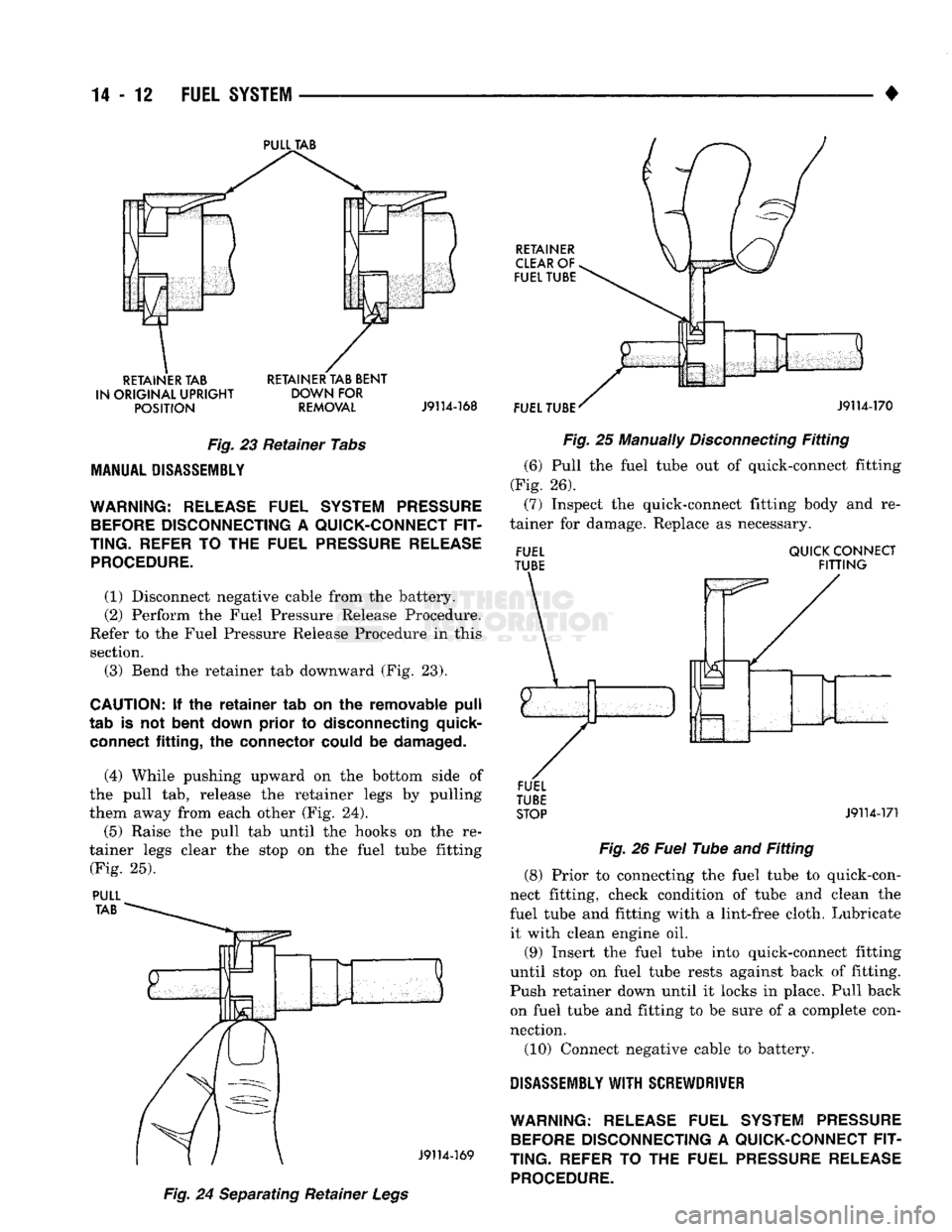
Refer to the Fuel Pressure Release Procedure in this section. (3) Bend the retainer tab downward (Fig. 23).
CAUTION:
If the
retainer
tab on the removable
pull
tab is not
bent
down
prior
to disconnecting quick- connect
fitting,
the connector could be
damaged.
(4) While pushing upward on the bottom side of
the pull tab, release the retainer legs by pulling
them away from each other (Fig. 24).
(5) Raise the pull tab until the hooks on the re
tainer legs clear the stop on the fuel tube fitting (Fig. 25).
PULL Fig.
24 Separating Retainer
Legs Fig.
25 Manually
Disconnecting
Fitting
(6) Pull the fuel tube out of quick-connect fitting
(Fig. 26). (7) Inspect the quick-connect fitting body and re
tainer for damage. Replace as necessary.
FUEL QUICK CONNECT
TUBE
FITTING
STOP
J9114-171
Fig.
26
Fuel
Tube and
Fitting
(8) Prior to connecting the fuel tube to quick-con
nect fitting, check condition of tube and clean the
fuel tube and fitting with a lint-free cloth. Lubricate
it with clean engine oil.
(9) Insert the fuel tube into quick-connect fitting
until stop on fuel tube rests against back of fitting. Push retainer down until it locks in place. Pull back
on fuel tube and fitting to be sure of a complete con
nection.
(10) Connect negative cable to battery.
DISASSEMBLY
WITH
SCREWDRIVER WARNING:
RELEASE
FUEL
SYSTEM PRESSURE
BEFORE
DISCONNECTING
A
QUICK-CONNECT FIT
TING.
REFER
TO THE
FUEL
PRESSURE RELEASE
PROCEDURE.
Page 832 of 1502
•
FUEL
SYSTEM
14 - 13 (1) Disconnect negative cable from the battery.
(2) Perform the Fuel Pressure Release Procedure.
Refer to the Fuel Pressure Release Procedure in this section.
(3) Bend the retainer tab downward.
CAUTION:
If the
retainer
tab on the
removable
pull
tab
is not
bent
down
prior
to
disconnecting
the
quick-connect
fitting,
the
connector
could
be
dam
aged.
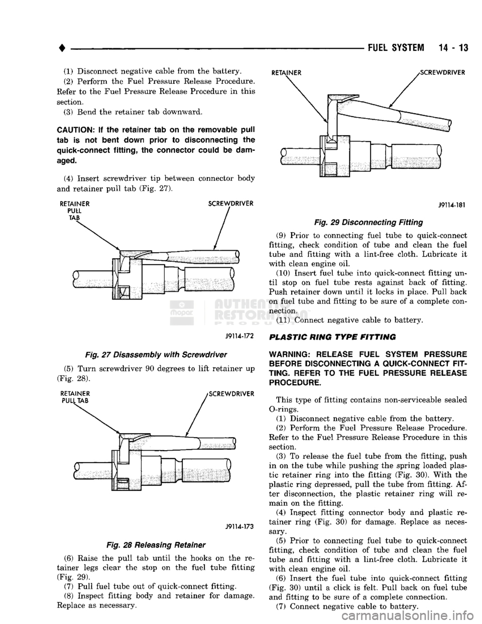
(4) Insert screwdriver tip between connector body
and retainer pull tab (Fig. 27).
RETAINER
SCREWDRIVER
J9114-172
J9114-181
Fig.
29
Disconnecting
Fitting
(9) Prior to connecting fuel tube to quick-connect
fitting, check condition of tube and clean the fuel
tube and fitting with a lint-free cloth. Lubricate it
with clean engine oil.
(10) Insert fuel tube into quick-connect fitting un
til stop on fuel tube rests against back of fitting.
Push retainer down until it locks in place. Pull back on fuel tube and fitting to be sure of a complete con
nection.
(11) Connect negative cable to battery.
PLASTIC RING TYPE FITTING
Fig.
27
Disassembly
with
Screwdriver
(5) Turn screwdriver 90 degrees to lift retainer up
(Fig. 28).
RETAINER
PULL
TAB
SCREWDRIVER
J9114-173
Fig.
28
Releasing
Retainer
(6) Raise the pull tab until the hooks on the re
tainer legs clear the stop on the fuel tube fitting
(Fig. 29). (7) Pull fuel tube out of quick-connect fitting.
(8) Inspect fitting body and retainer for damage.
Replace as necessary.
WARNING:
RELEASE
FUEL
SYSTEM PRESSURE
BEFORE
DISCONNECTING
A
QUICK-CONNECT FIT
TING.
REFER
TO THE
FUEL
PRESSURE RELEASE PROCEDURE.
This type of fitting contains non-serviceable sealed
O-rings. (1) Disconnect negative cable from the battery.
(2) Perform the Fuel Pressure Release Procedure.
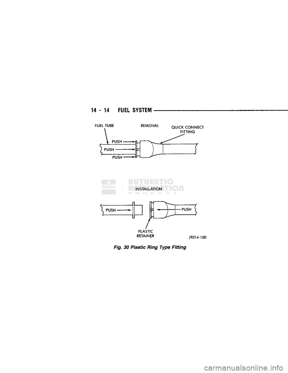
Refer to the Fuel Pressure Release Procedure in this section. (3) To release the fuel tube from the fitting, push
in on the tube while pushing the spring loaded plas
tic retainer ring into the fitting (Fig. 30). With the
plastic ring depressed, pull the tube from fitting. Af ter disconnection, the plastic retainer ring will re
main on the fitting.
(4) Inspect fitting connector body and plastic re
tainer ring (Fig. 30) for damage. Replace as neces sary.
(5) Prior to connecting fuel tube to quick-connect
fitting, check condition of tube and clean the fuel
tube and fitting with a lint-free cloth. Lubricate it
with clean engine oil.
(6) Insert the fuel tube into quick-connect fitting
(Fig. 30) until a click is felt. Pull back on fuel tube
and fitting to be sure of a complete connection.
(7) Connect negative cable to battery.
Page 833 of 1502
14 - 14
FUEL
SYSTEM
FUEL TUBE
REMOVAL
QUICK CONNECT
FITTING
PUSH
INSTALLATION
^ PUSH
»-
/
PLASTIC
RETAINER
J93U-100
Fig.
30 Plastic
Ring
Type Fitting
•PUSH
Page 834 of 1502
FUEL
DELIVERY—DIESEL
ENGINE
INDEX
page
Fuel Gauge Sending Unit Module
15
General Information
15
Manual
Shut Down Lever
. . 17
page
Mechanical
Lift
Pump
15
Quick
Connect Fittings—Except
Chassis
Fuel Tubes
17
GENERAL
INFORMATION
The fuel system of the 5.9L turbo-diesel engine
consists of the:
• Fuel tank • Low and high pressure fuel supply lines
• Mechanical lift pump
• Fuel/water separator filter
• Fuel heater
• Fuel injection pump • Fuel injectors
• Fuel return lines For information regarding fuel requirements of the
5.9L turbo diesel engine, refer to the Fuel Require
ments—Diesel Engines paragraph at the front of this group.
MECHANICAL
LIFT
PUMP
The mechanical lift pump is located on the left side
of the engine cylinder block. The lift pump is driven
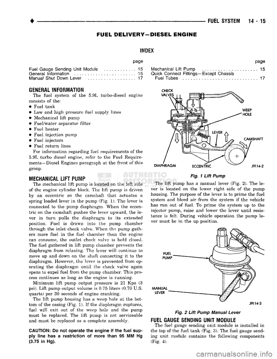
by an eccentric on the camshaft that actuates a spring loaded lever in the pump (Fig. 1). The lever is
connected to the pump diaphragm. When the eccen
tric on the camshaft pushes the lever upward, the le ver in turn pulls the diaphragm to its extended
position. Fuel is drawn into the pump chamber
through the inlet check valve. When the pump gath ers more fuel in the fuel chamber than the engine
can consume, the outlet check valve is held closed.
The fuel gathered in lift pump chamber prevents the diaphragm from relaxing. The lever will continue to
move up and down on the shaft connecting it to the
diaphragm. However, the lever is prevented from op
erating the diaphragm until the check valve again
opens to expel fuel from the pump chamber. This pro cess continues as long as the engine is running.
Minimum lift pump output pressure is 21 Kpa (3
psi).
Lift pump output volume is 0.75 liters (0.70 U.S. quarts) per 30 seconds of engine cranking. The lift pump housing has a weep hole at the bot
tom of the casing (Fig. 1). If the diaphragm ruptures,
fuel will exit out of the weep hole and the pump
must be replaced. The lift pump is not serviceable and must be replaced as a complete assembly.
CAUTION:
Do not
operate
the
engine
if the
fuel
supply
line
has a
restriction
of
more than
95 MM Hg
(3.75
in Hg).
Fig.
1
Lift
Pump
The lift pump has a manual lever.(Fig. 2). The le
ver is located on the lower right side of the pump
housing. The purpose of the lever is to prime the fuel system and bleed air from the system if the vehicle
has run out of fuel. To prime the system up to the injector pump, raise and lower the lever until resis
tance is felt. During vehicle operation the pump le
ver must be in the up position.
J9114-3
Fig.
2
Lift
Pump
Manual
Lever
FUEL GAUGE SENDING
UNIT
MODULE
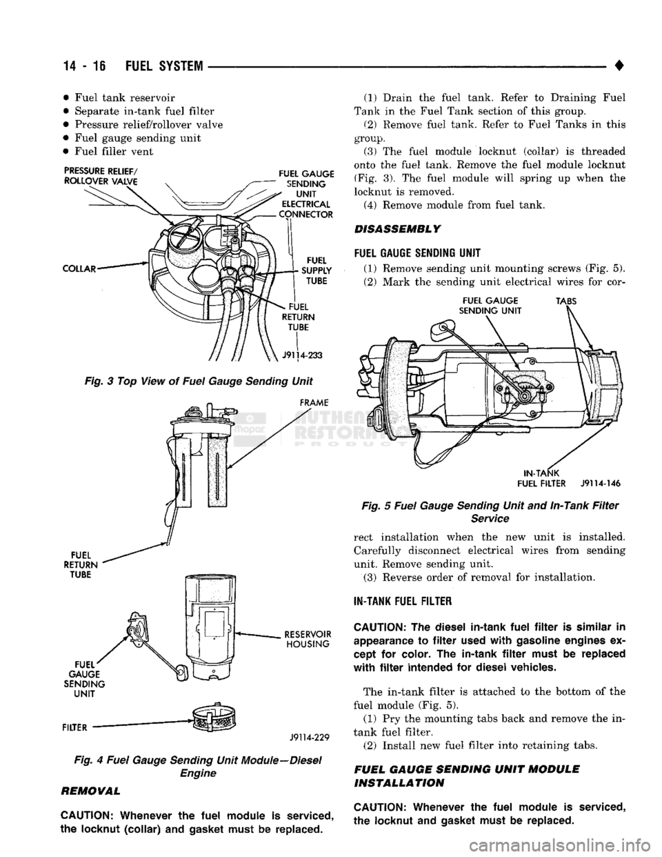
The fuel gauge sending unit module is installed in
the top of the fuel tank (Fig. 3). The fuel gauge send ing unit module contains the following components (Fig. 4).
Page 835 of 1502
14-16 FUEL SYSTEM
• • Fuel tank reservoir
• Separate in-tank fuel filter
• Pressure relief/rollover valve
• Fuel gauge sending unit
• Fuel filler vent
Fig. 3 Top View of Fuel Gauge Sending Unit
J9114-229
Fig. 4 Fuel Gauge Sending Unit Module--Diesel Engine
REMOVAL
CAUTION:
Whenever
the
fuel
module
is
serviced,
the
locknut
(collar)
and
gasket must
be
replaced. (1)
Drain the fuel tank. Eefer to Draining Fuel
Tank in the Fuel Tank section of this group.
(2) Remove fuel tank. Refer to Fuel Tanks in this
group.
(3)
The fuel module locknut (collar) is threaded
onto the fuel tank. Remove the fuel module locknut (Fig. 3). The fuel module will spring up when the
locknut is removed. (4) Remove module from fuel tank.
DISASSEMBLY
FUEL
GAUGE SENDING
UNIT
(1) Remove sending unit mounting screws (Fig. 5).
(2) Mark the sending unit electrical wires for cor-
FUEL
GAUGE TABS
IN-TANK
FUEL FILTER
J9114-146
Fig. 5 Fuel Gauge Sending Unit and In-Tank Filter Service
rect installation when the new unit is installed. Carefully disconnect electrical wires from sending
unit. Remove sending unit.
(3)
Reverse order of removal for installation.
IN-TANK
FUEL FILTER
CAUTION:
The
diesel in-tank
fuel
filter is
similar
in
appearance
to filter
used
with
gasoline engines
ex
cept
for
color.
The
in-tank
filter
must
be
replaced
with
filter
intended
for
diesel vehicles.
The in-tank filter is attached to the bottom of the
fuel module (Fig. 5). (1) Pry the mounting tabs back and remove the in-
tank fuel filter. (2) Install new fuel filter into retaining tabs.
FUEL GAUGE SENDING UNIT MODULE INSTALLATION
CAUTION:
Whenever
the
fuel
module
is
serviced,
the locknut
and
gasket must
be
replaced.
Page 836 of 1502
•
FUEL SYSTEM
14-17
(1) Using
a new
gasket, position fuel module into
opening
in
fuel tank.
(2) Position
new
locknut over
top of
fuel module.
(3) Tighten locknut. (4) Install fuel tank. Refer
to
Fuel Tank Installa
tion
in
this section.
MANUAL SHUT
DOWN
LE¥ER
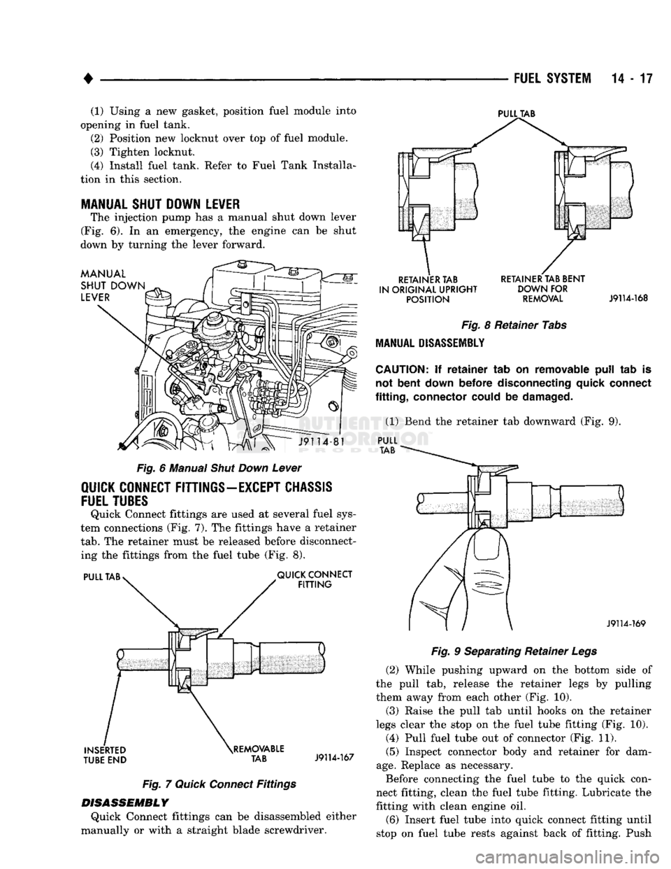
The injection pump
has a
manual shut down lever
(Fig.
6). In an
emergency,
the
engine
can be
shut
down
by
turning
the
lever forward.
Fig.
6
Manual
Shut
Down
Lever
QUICK CONNECT
FITTINGS-EXCEPT
CHASSIS
FUEL TUBES
Quick Connect fittings
are
used
at
several fuel sys
tem connections
(Fig. 7). The
fittings have
a
retainer
tab.
The
retainer must
be
released before disconnect
ing
the
fittings from
the
fuel tube
(Fig. 8).
Fig.
7
Quick
Connect
Fittings
DISASSEMBLY
Quick Connect fittings
can be
disassembled either
manually
or
with
a
straight blade screwdriver.
PULL
TAB
RETAINER
TAB
RETAINER
TAB
BENT
IN
ORIGINAL
UPRIGHT DOWN FOR
POSITION
REMOVAL
J9114-168
Fig.
8
Retainer Tabs
MANUAL
DISASSEMBLY
CAUTION:
If
retainer
tab on
removable
pull
tab is
not
bent
down
before
disconnecting quick connect
fitting,
connector could
be
damaged.
(1) Bend
the
retainer
tab
downward
(Fig. 9).
PULL
Fig.
9
Separating Retainer
Legs
(2) While pushing upward
on the
bottom side
of
the pull
tab,
release
the
retainer legs
by
pulling
them away from each other
(Fig. 10).
(3) Raise
the
pull
tab
until hooks
on the
retainer
legs clear
the
stop
on the
fuel tube fitting
(Fig. 10).
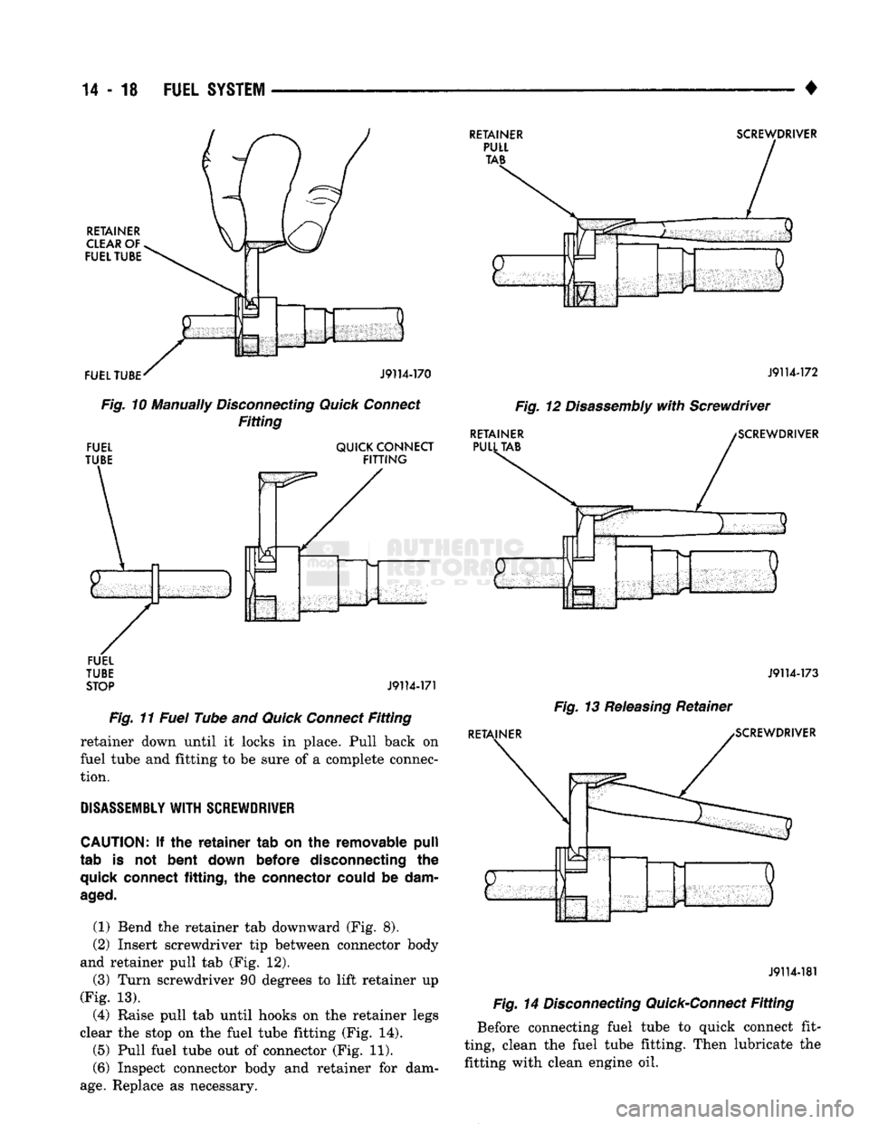
(4) Pull fuel tube
out of
connector
(Fig. 11).
(5) Inspect connector body
and
retainer
for
dam
age.
Replace
as
necessary.
Before connecting
the
fuel tube
to the
quick con
nect fitting, clean
the
fuel tube fitting. Lubricate
the
fitting with clean engine
oil.
(6) Insert fuel tube into quick connect fitting until
stop
on
fuel tube rests against back
of
fitting. Push
Page 837 of 1502
14
- 18
FUEL
SYSTEM
•
RETAINER
CLEAR
OF
FUEL TUBE FUEL TUBE
RETAINER
PULL TAB
SCREWDRIVER
ff
t
iiiilil
J9114-170
Fig.
10 Manually
Disconnecting
Quick
Connect
Fitting
FUEL
TUBE QUICK CONNECT
FITTING
RETAINER
PULL TAB
J9114-172
Fig.
12
Disassembly
with
Screwdriver
SCREWDRIVER
FUEL
TUBE STOP
J9114-171
Fig.
11
Fuel
Tube and
Quick
Connect
Fitting
retainer down until it locks in place. Pull back on
fuel tube and fitting to be sure of a complete connec
tion.
DISASSEMBLY
WITH
SCREWDRIVER
CAUTION:
If the
retainer
tab on the removable
pull
tab is not
bent
down
before
disconnecting the
quick
connect
fitting,
the
connector could
be
dam
aged.
(1) Bend the retainer tab downward (Fig. 8).
(2) Insert screwdriver tip between connector body
and retainer pull tab (Fig. 12).
(3) Turn screwdriver 90 degrees to lift retainer up
(Fig. 13).
(4) Raise pull tab until hooks on the retainer legs
clear the stop on the fuel tube fitting (Fig. 14). (5) Pull fuel tube out of connector (Fig. 11).
(6) Inspect connector body and retainer for dam
age.
Replace as necessary.
J9114-173
Fig.
13
Releasing
Retainer
RETAINER ^SCREWDRIVER
J9114-181
Fig.
14
Disconnecting
Quick-Connect
Fitting
Before connecting fuel tube to quick connect fit
ting, clean the fuel tube fitting. Then lubricate the fitting with clean engine oil.
Page 838 of 1502
•
FUEL
SYSTEM
14 - 19 (7) Insert fuel tube into quick connect fitting until
stop on fuel tube rests against back of fitting. Push
retainer down until it locks in place. Pull back on
fuel tube and fitting to be sure of a complete connec
tion.
CHASSIS
FUEL
TUBE
QUICK-CONNECT
FITTINGS
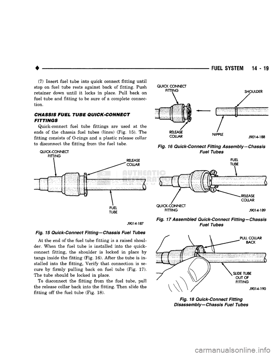
Quick-connect fuel tube fittings are used at the
ends of the chassis fuel tubes (lines) (Fig. 15). The
fitting consists of O-rings and a plastic release collar
to disconnect the fitting from the fuel tube.
QUICK-CONNECT
FITTING
FUEL
J9014-187
Fig.
15
Quick-Connect
Fitting—Chassis
Fuel
Tubes
At the end of the fuel tube fitting is a raised shoul
der. When the fuel tube is installed into the quick-
connect fitting, the shoulder is locked in place by
tangs inside the fitting (Fig. 16). After the tube is in stalled into the fitting, Verify that connection is se
cure by firmly pulling back on fuel tube (Fig. 17).
The tube should be locked in place.
To disconnect the fitting from the fuel tube, pull
the release collar back into the fitting. Then slide the
fitting off the fuel tube (Fig. 18).
QUICK
CONNECT
COLLAR
,wrLC
J9014-188
Fig.
16
Quick-Connect
Fitting
Assembly—Chassis
Fuel
Tubes
FUEL
TUBE
QUICK-CONNECT
FITTING
J9014-189
Fig.
17
Assembled
Quick-Connect
Fitting—Chassis
Fuel
Tubes
Fig.
18
Quick-Connect
Fitting
Disassembly—
Chassis
Fuel
Tubes
Page 839 of 1502
14-20 FUEL
SYSTEM
•
FUEL
TANKS
INDEX
page
Fuel Gauge Sending
Unit
24
Fuel Pump
22
Fuel Reservoir
23
Fuel Tank
Filler
Tube
Cap 20
Fuel Tank Pressure Relief/Rollover Valve
...... 24
GENERAL
INFORMATION
All Dodge Trucks pass a full 360 degree rollover with
out fuel leakage. To accomplish this, fuel and vapor
flow controls are required for all fuel tank connections. All models have a pressure relief/rollover valve
mounted in the top of the fuel tank. On vehicles equipped with a return line from fuel pump to fuel
tank, a one-way check valve is used to provide required
protection. In addition to the valve, improved flow con trol is used in the fuel pump. Fuel flow is controlled if
pump is subjected to higher than normal pressure dur ing rollover. For the same reason, a fuel tank filler tube
cap (gas cap) with higher pressure setting is used to
control fuel flow on vehicles with side fill. An evaporation control system is used to reduce
emissions of fuel vapors into atmosphere by evapora
tion and to reduce unburned hydrocarbons emitted
by vehicle engine. When fuel evaporates from fuel
tank, vapors pass through vent hoses or tubes to a
charcoal canister. The are temporarily held in the
canister. When the engine is running, the vapors are
drawn into intake manifold. Refer to Group 25,
Emission Control System for additional information. Inspect all hose connections to make sure they are
secure and not leaking. Hoses should be replaced im
mediately if there is any evidence of degradation
that could result in failure. Avoid contact with clamps or other components
that cause abrasions or scuffing. Be sure that the
rubber hoses are properly routed to prevent pinching and to avoid heat sources.
The hoses used on fuel injected vehicles are of a
special construction due to higher fuel pressures in
volved in system. If hoses need replacement, only use
hoses marked EFM/EFI.
The hose clamps used on fuel injected vehicles have
a special rolled edge construction. This prevents the
edge of the clamp from cutting into the hose. Only
these rolled edge type clamps may be used on this system. Other clamps may cut into the hoses. This
could cause high pressure fuel leaks.
NO-LEAD FUEL TANK FILLER TUBE
All catalyst equipped vehicles have a special fuel
tank filler tube. The fuel filler opening is smaller in
page
Fuel Tank Skid
Plate
. 20
Fuel Tanks
21
General
Information
20
Heat Shields
21
No-Lead
Fuel Tank
Filler
Tube
20
diameter than those used for non-catalyst vehicles to
permit entry of only the smaller no-lead fuel nozzles.
A deflector is installed in the fuel filler opening. The
deflector is opened by the no-lead fuel nozzle. The fuel filler tube on these models has a one-way
ball check valve. The valve is designed to prevent
fuel back splash which may occur while filling the tank. A label is attached to instrument panel under fuel
gauge that reads UNLEADED FUEL ONLY as a re
minder to driver. A similar label is located near fuel
tank filler.
FUEL TANK FILLER TUBE
CAP The loss of any fuel or vapor out of filler neck is
prevented by the use of a pressure-vacuum fuel tank
filler tube cap. Relief valves inside cap will release only under significant pressure of 6.58 to 8.44 kPa (1.95 to 2.5 psi). The vacuum release for all gas caps
is between .97 and 2.0 kPa (.14 and .29 psi). This cap
must be replaced by a similar unit if replacement is necessary. This is in order for the system to remain
effective.
CAUTION:
Remove
fuel
tank
filler
tube
cap
before
servicing
any
fuel
system component. This
is
done
to help
relieve
tank pressure.
FUEL
TANK
CAPACITIES
TANK:
LITERS
GALLONS
Standard
83.0
22
Optional 114
30
Ramcharger 120.9 34
Nominal
refill
capacities are
shown.
A variation may be observed
from vehicle to vehicle due to manufacturing tolerances and
refill
procedures.
J9014-182
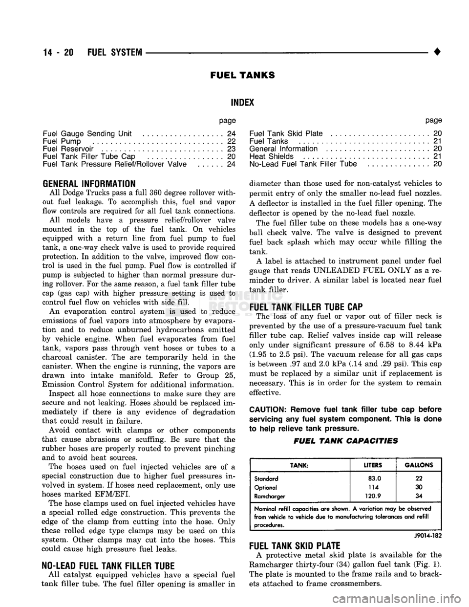
FUEL TANK SKID PLATE
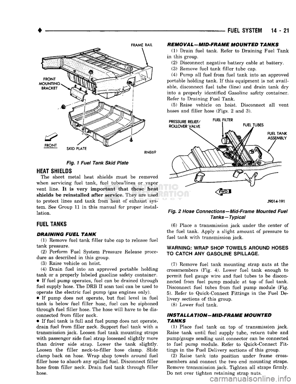
A protective metal skid plate is available for the
Ramcharger thirty-four (34) gallon fuel tank (Fig. 1).
The plate is mounted to the frame rails and to brack ets attached to frame crossmembers.
Page 840 of 1502
•
FUEL
SYSTEM
14-21
FRAME
RAIL
SKID
PLATE
RN869
Fig.
1
Fuel
Tank
Skid
Plate
HEAT
SHIELDS
The sheet metal heat shields must be removed
when servicing fuel tank, fuel tubes/lines or vapor
vent line. It is very important that these heat shields be reinstalled after service. They are used
to protect lines and tank from heat of exhaust sys
tem. See Group 11 in this manual for proper instal lation.
FUEL
TANKS
DRAINING
FUEL
TANK
(1) Remove fuel tank filler tube cap to release fuel
tank pressure. (2) Perform Fuel System Pressure Release proce
dure as described in this group.
(3) Raise vehicle on hoist.
(4) Drain fuel into an approved portable holding
tank or a properly labeled gasoline safety container.
• If fuel pump operates, fuel can be drained through
fuel supply hose. The DRB II scan tool can be used to operate the electric fuel pump (gas engines only).
• If pump does not operate, but fuel level in fuel
tank is below fuel filler hose, fuel can be siphoned
through fuel filler hose. The hose will have to be dis connected from filler neck.
• If fuel tank is full and fuel pump does not operate,
drain fuel from filler neck. Support fuel tank with a
transmission jack. Loosen fuel tank mounting straps with passenger side fuel strap loosened slightly more
than driver side strap. Lower the tank slightly. Loosen the filler neck-to-filler hose clamp. Slide
clamp back on hose. Wrap shop towels around fuel
filler hose to absorb any spilled fuel. Disconnect filler
hose from filler neck. Drain fuel tank through filler
hose.
REMOVAL-MID-FRAME
MOUNTED
TANKS
(1) Drain fuel tank. Refer to Draining Fuel Tank
in this group. (2) Disconnect negative battery cable at battery.
(3) Remove fuel tank filler tube cap.
(4) Pump all fuel from fuel tank into an approved
portable holding tank. If this equipment is not avail
able,
disconnect fuel tube (line) and drain tank dry
into a properly identified Gasoline safety container.
Refer to Draining Fuel Tank.
(5) Raise vehicle on hoist. Disconnect all vent
hoses and filler hose (Figs. 2 and 3).
PRESSURE
RELIEF/
FUEL F,LTER
J9014-191
Fig.
2
Hose
Connections—Mid-Frame
Mounted
Fuel
Tanks—Typical (6) Place a transmission jack under the center of
the fuel tank. Apply a slight amount of pressure to fuel tank with transmission jack.
WARNING:
WRAP
SHOP
TOWELS
AROUND
HOSES
TO
CATCH
ANY
GASOLINE
SPILLAGE.
(7) Remove fuel tank mounting strap nuts at the
crossmembers (Fig. 4). Lower fuel tank enough to
permit fuel gauge wire and fuel tubes to be discon nected from fuel pump module at top of fuel tank.
Disconnect fuel tubes from fuel pump module (Fig.
5).
Refer to Quick-Connect Fittings in the Fuel De
livery sections of this group.
(8) Lower fuel tank.
INSTALLA
TION—MID-FRAME
MOUNTED
TANKS (1) Place fuel tank on top of transmission jack.
Raise tank until fuel supply tube, return tube and
pump/gauge sending unit connector can be connected to fuel pump module. Refer to Quick-Connect Fit
tings in the Fuel Delivery sections of this group.
(2) Raise tank into position under frame cross-
members and connect the two end mounting straps.
Remove transmission jack. Tighten all straps firmly.
Do not over tighten retaining strap nuts.