DODGE TRUCK 1993 Service Repair Manual
Manufacturer: DODGE, Model Year: 1993, Model line: TRUCK, Model: DODGE TRUCK 1993Pages: 1502, PDF Size: 80.97 MB
Page 811 of 1502
Page 812 of 1502
FRAME
AND
BUMPERS
13 - 25
FUNCTION
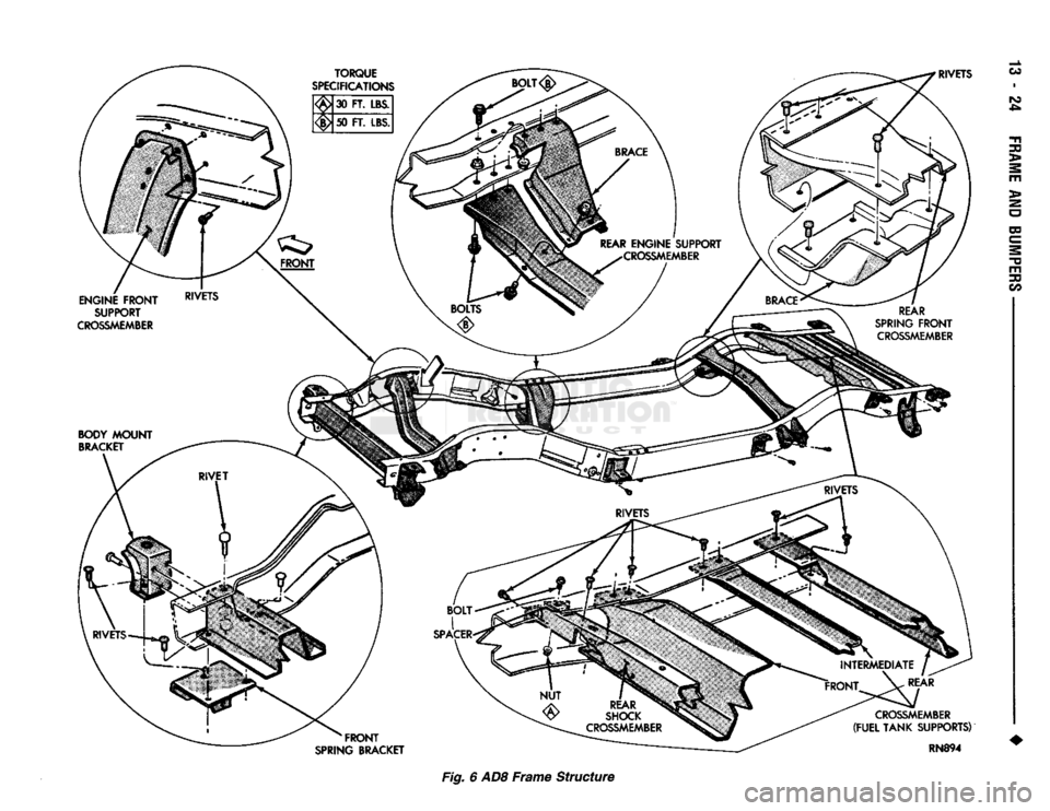
The frame is the foundation and the structural cen
ter of the vehicle. The primary function of a frame is
to provide support and attachment locations: • For all the chassis/drivetrain components
• For the cab/body
• For the vehicle payload While limiting deflections and twisting of the
frame members. The frame maintains the correct relationship and
alignment of the powertrain. This relationship and
alignment ensures normal operation of the attached
units.
CONSTRUCTION MATERIAL High-strength, carbon steel with a minimum yield
strength of 32,000 psi is used to construct frame side
rails.
A frame made of 32,000 psi minimum yield
strength steel has, in reality, a range of 32,000 to
44,000 psi yield strength.
For 4WD vehicle applications, the frame side rails
reinforcements are constructed of the same high- strength, carbon steel as the side rails.
BENDING RESISTANCE A frame reacts to its load and the road surface de
viations by deflecting and twisting. The primary de
flecting frame members are the side rails. Resistance
to frame twist is provided by the crossmembers.
FRAME
INSPECTION/MEASUREMENTS
INSPECTION Inspect the frame members for visible damage and
metal deformations. Inspect all riveted, bolted and
welded connections for looseness and/or missing hardware. All damaged areas must be repaired and/or the
frame members replaced, as necessary.
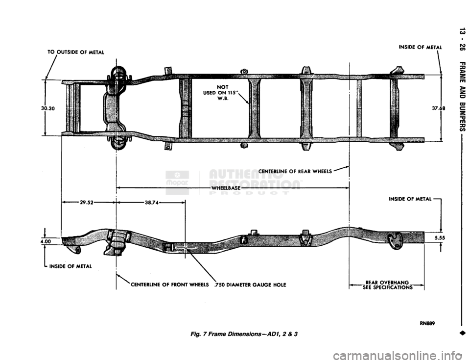
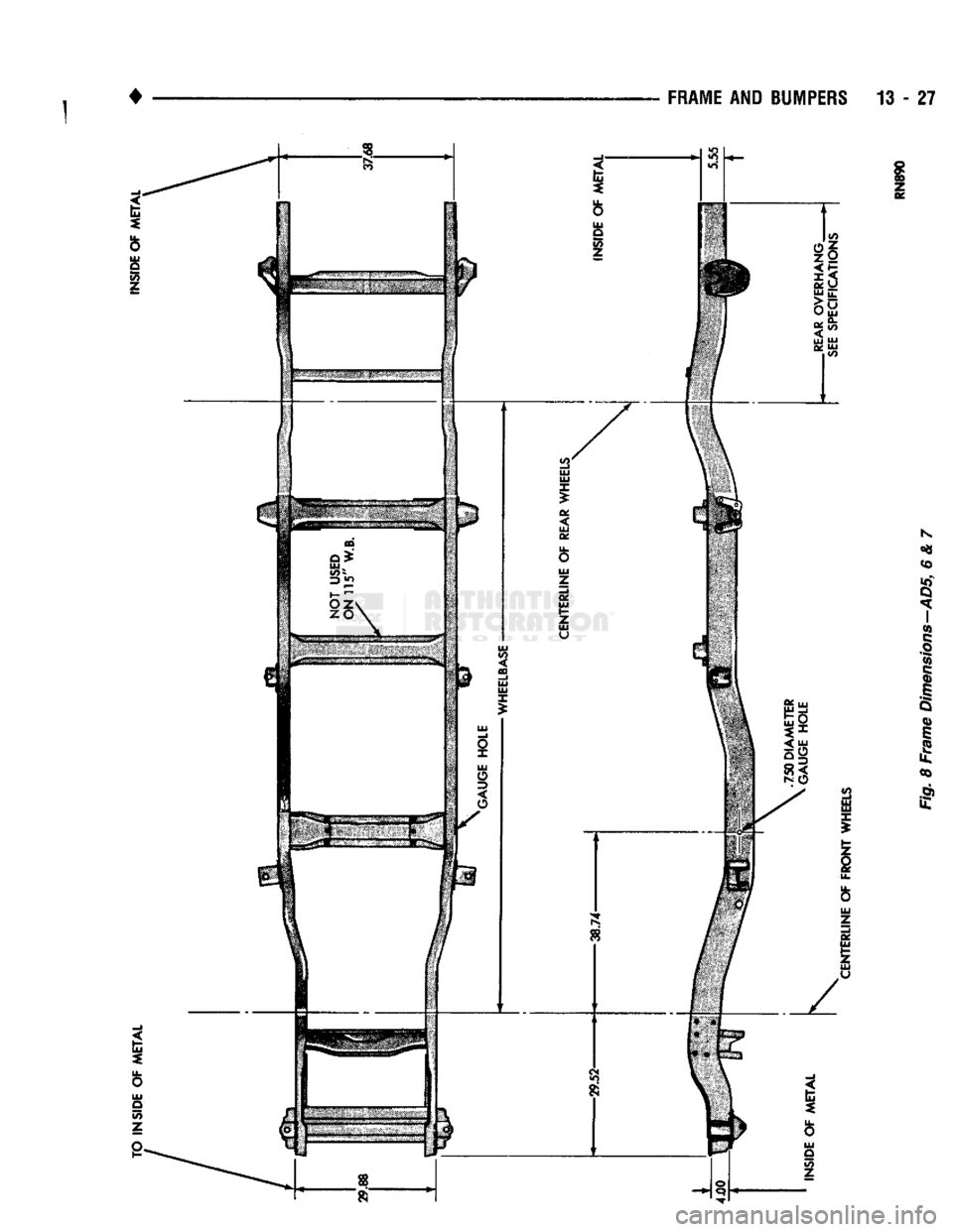
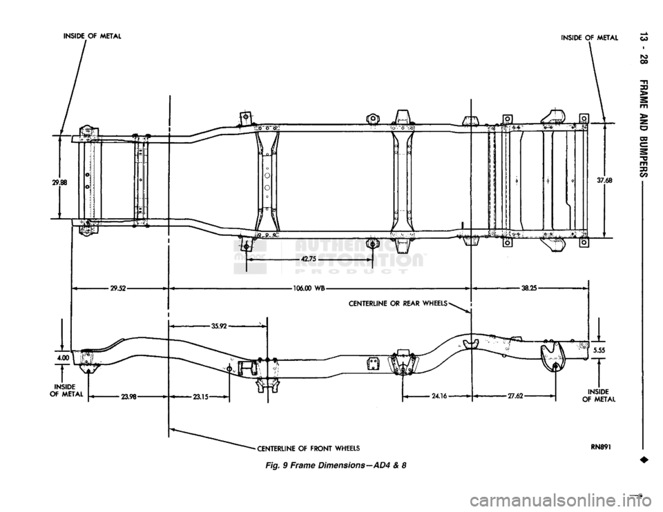
MEASUREMENTS Measure the frame for mis-alignment with the cab/
body and cargo box attached to the frame. Figures 7, 8, 9 provide the frame alignment reference dimen
sions.
The following information applies to all measure
ments.
(1) Place the vehicle on a level surface.
(2) If the vehicle is loaded, verify the vehicle does
not exceed the gross vehicle weight rating (GVWR).
Verify the load is distributed in the vehicle as evenly as possible. For better measurement results, remove
the cargo/payload from the vehicle.
(3) Measure the tire inflation pressures. Adjust as
necessary.
HORIZONTAL/DIAGONAL
FRAME MEASUREMENTS
Determine the frame horizontal, according to the
following procedure.
(1) Select several reference points along one frame
side rail, preferably at the crossmember junctions.
(2) Transfer these reference points to the surface/
floor. Paper sheets can be attached to the surface be low the reference points.
(3) Locate the same reference points on the other
frame side rail. Transfer them to the surface/floor.
(4) Move the vehicle away. Measure between all
the reference points diagonally from and parallel to
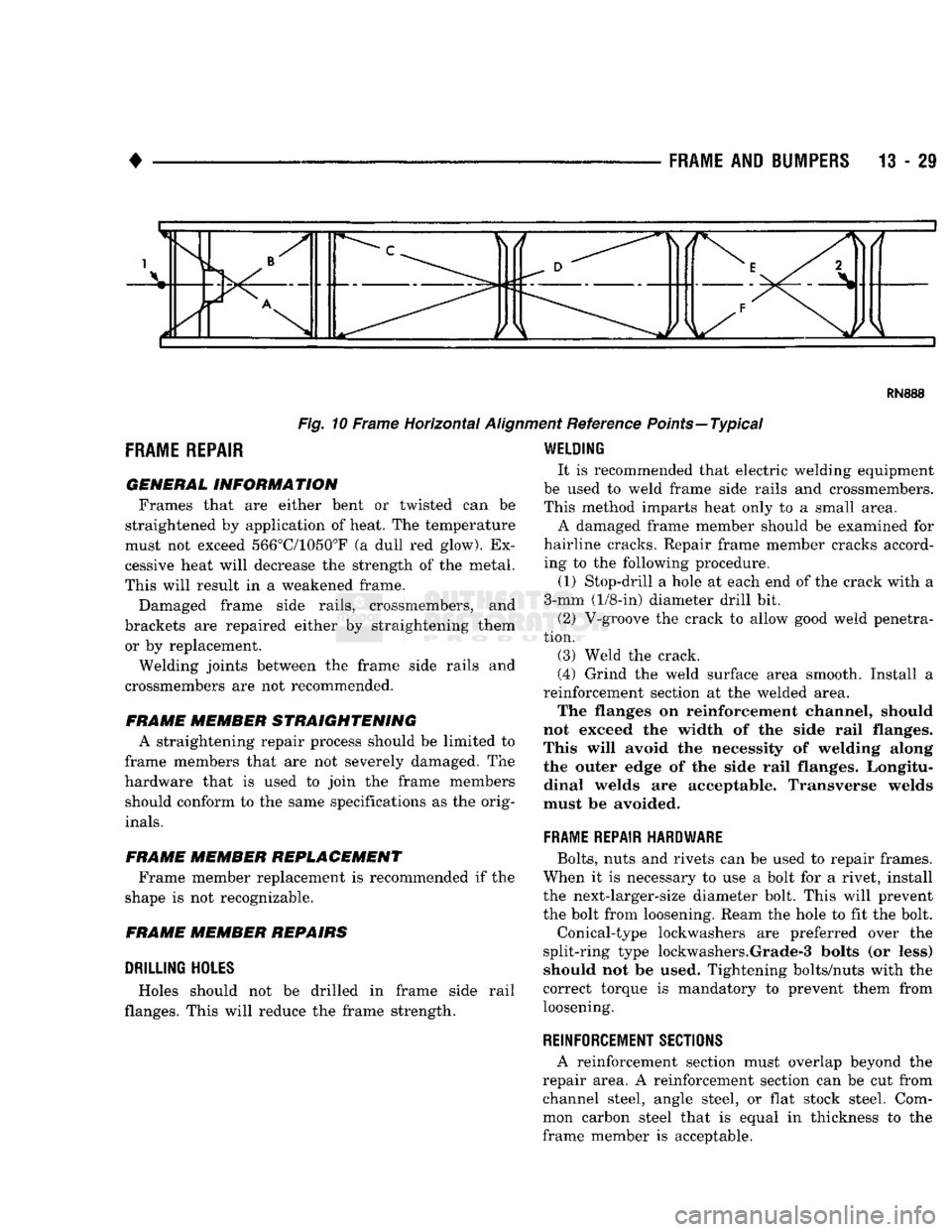
the side rails (Fig. 10). The corresponding measure ments should not differ by more than 6 mm (1/4 in).
(5)
Measure the distance between the two front
reference points. Measure the distance between the
two rear reference points. Divide each distance in
half and indicate the two half-way points on the sur
face/floor. Designate the front point as 1 and the rear
point as 2 (Fig. 10).
(6) Place a chalk-line between points 1 and 2 (Fig.
10) and snap the string.
(7) Determine how close the center line is to the
diagonal intersection points in Figure 10.
(8) The marks on the floor will show the amount of
frame misalignment.
(9) The reference point transferred from one side
rail should be within 3 mm (1/8 in) of the opposite
reference point.
(10) Frame bow to the side should not exceed 3
mm per 2540 mm (1/8 inch per 100 inches) in frame
length.
(11) The overall width of the frame should not
vary more than 3 mm (1/8 in). (12) Repeat steps (1) through (11) after straighten
ing the frame.
Refer to Figures 7, 8, and 9 for frame horizon
tal alignment reference dimensions.
TWIST
AND PARALLEL FRAME MEASUREMENTS
Determine the amount of frame twist using the fol
lowing procedure.
(1) Mark the vertical reference points under the
frame side rails at 305-mm (12-in) intervals. Start at
the rear frame crossmember.
(2) Measure the distance up from a level surface/
floor to each corresponding reference point. (3) The distance to a reference point under one
side rail should be a maximum of 3 mm (1/8 in)
dif
ference than the opposite side rail.
Refer to Figures 7, 8 and 9 for frame vertical
alignment reference dimensions.
Page 813 of 1502
TO OUTSIDE
OF
METAL
INSIDE
OF
METAL
37.68
CENTERLINE
OF
FRONT
WHEELS
750
DIAMETER GAUGE HOLE 5.55
REAR
OVERHANG
'SEE
SPECIFICATIONS"
Fig. 7
Frame
Dimensions—AD1, 2 & 3
mm
Page 814 of 1502
•
FRAME
AND BUMPERS 13 - 27
Page 815 of 1502
Page 816 of 1502
RN888
Fig.
10 Frame Horizontal
Aligi
FRAME
REPAIR
GENERAL
INFORMATION
Frames that are either bent or twisted can be
straightened by application of heat, The temperature
must not exceed 566°C/1050°F (a dull red glow). Ex
cessive heat will decrease the strength of the metal.
This will result in a weakened frame.
Damaged frame side rails, crossmembers, and
brackets are repaired either by straightening them or by replacement.
Welding joints between the frame side rails and
crossmembers are not recommended.
FRAME MEMBER
STRAIGHTENING
A straightening repair process should be limited to
frame members that are not severely damaged. The
hardware that is used to join the frame members should conform to the same specifications as the orig
inals.
FRAME MEMBER
REPLACEMENT Frame member replacement is recommended if the
shape is not recognizable.
FRAME
MEMBER REPAIRS
DRILLING
HOLES
Holes should not be drilled in frame side rail
flanges. This will reduce the frame strength. ent Reference Points—Typical
WELDING
It is recommended that electric welding equipment
be used to weld frame side rails and crossmembers. This method imparts heat only to a small area.
A damaged frame member should be examined for
hairline cracks. Repair frame member cracks accord ing to the following procedure.
(1) Stop-drill a hole at each end of the crack with a
3-mm (1/8-in) diameter drill bit.
(2) V-groove the crack to allow good weld penetra
tion. (3) Weld the crack.
(4) Grind the weld surface area smooth. Install a
reinforcement section at the welded area. The flanges on reinforcement channel, should
not exceed the width of the side rail flanges.
This will avoid the necessity of welding along
the outer edge of the side rail flanges. Longitu dinal welds are acceptable. Transverse welds
must be avoided.
FRAME REPAIR HARDWARE
Bolts,
nuts and rivets can be used to repair frames.
When it is necessary to use a bolt for a rivet, install
the next-larger-size diameter bolt. This will prevent
the bolt from loosening. Ream the hole to fit the bolt.
Conical-type lockwashers are preferred over the
split-ring type lockwashers.Grade-3 bolts (or less) should not be used. Tightening bolts/nuts with the
correct torque is mandatory to prevent them from
loosening.
REINFORCEMENT SECTIONS
A reinforcement section must overlap beyond the
repair area. A reinforcement section can be cut from channel steel, angle steel, or flat stock steel. Com
mon carbon steel that is equal in thickness to the
frame member is acceptable.
Page 817 of 1502
13
- 30 FRAME AND BUMPERS
ATTACHED COMPONENTS
SKID
PLATES
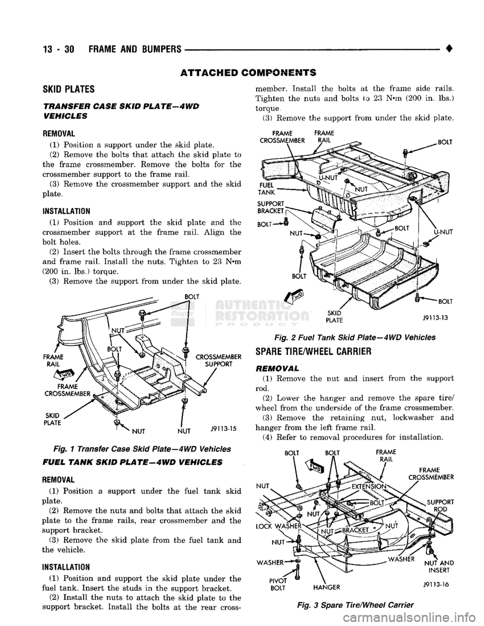
TRANSFER CASE SKID
PL
ATF
4 WD
VEHICLES
REMOVAL
(1) Position
a
support under
the
skid plate.
(2) Remove
the
bolts that attach
the
skid plate
to
the frame crossmember. Remove
the
bolts
for the
crossmember support
to the
frame rail.
(3) Remove
the
crossmember support
and the
skid
plate.
INSTALLATION
(1) Position
and
support
the
skid plate
and the
crossmember support
at the
frame rail. Align
the
bolt holes.
(2) Insert
the
bolts through
the
frame crossmember
and frame rail. Install
the
nuts. Tighten
to 23 N*m
(200
in. lbs.)
torque.
(3) Remove
the
support from under
the
skid plate.
Fig.
1
Transfer
Case Skid
Plate—4WD Vehicles
FUEL TANK SKID
PLATE-4WD
VEHICLES
REMOVAL
(1) Position
a
support under
the
fuel tank skid
plate.
(2) Remove
the
nuts
and
bolts that attach
the
skid
plate
to the
frame rails, rear crossmember
and the
support bracket.
(3) Remove
the
skid plate from
the
fuel tank
and
the vehicle.
INSTALLATION
(1) Position
and
support
the
skid plate under
the
fuel tank. Insert
the
studs
in the
support bracket.
(2) Install
the
nuts
to
attach
the
skid plate
to the
support bracket. Install
the
bolts
at the
rear cross- member. Install
the
bolts
at the
frame side rails.
Tighten
the
nuts
and
bolts
to 23 N*m (200 in. lbs.)
torque.
(3) Remove
the
support from under
the
skid plate.
FRAME FRAME
Fig.
2
Fuel
Tank
Skid
Plate-4WD Vehicles
SPARE
TIRE/WHEEL
CARRIER
REMOVAL
(1) Remove
the nut and
insert from
the
support
rod. (2) Lower
the
hanger
and
remove
the
spare tire/
wheel from
the
underside
of the
frame crossmember.
(3) Remove
the
retaining
nut,
lockwasher
and
hanger from
the
left frame rail.
(4) Refer
to
removal procedures
for
installation. BOLT BOLT FRAME
Fig.
3
Spare
The/Wheel Carrier
Page 818 of 1502
1
•
FRAME
AND
BUMPERS
13 - 31 PIVOT BOL T ADJUSTMENT
(1) Refer to the Pivot Bolt Height chart and deter
mine the length of dimension A for the pivot bolt.
PIVOT BOLT HEIGHT
PIVOT BOLT HEIGHT
RIM SIZE TIRE SIZE BOLT HEIGHT
15 x 6.5 P195/75R-15
4.0"
P205/75R-15 4.0"
P235/75R-15XL
5.0"
15
x 7.0
P235/75R-15XL 5.2"
10R-15LT-B
5.62"
16 x 6.0 7.50-16 SINGLE & DUAL
6.75"
LT215/85R-16 SINGLE
4.5"
LT215/85R-16 DUAL 5.0"
LT235/85R-16
5.0"
16.5 x 6.0 8.00-16.5 SINGLE
4.12"
8.00-16.5 DUAL
5.0"
16.5 x 6.75 8.75-16.5 5.0"
NOTE: 7.50 x 16 TIRE SHOULD BE INSTALLED IN A DISH
UP POSITION ONLY
(2) Loosen the pivot bolt nut and adjust dimension
A to required length.
INSTALLATION (1) Position the hanger under the frame side rails
and insert the pivot bolt in the frame rail hole. (2) Install the lockwasher and the nut on the pivot
bolt. Tighten the nut to 61 N*m (45 ft. lbs).
(3) Position the spare tire/wheel on the hanger.
Raise the hanger and insert the support rod in the
hole.
(4) Install the washer,nut and insert on the sup
port rod. Tighten the nut to 11 Nnn (95 in. lbs.).
CAB
REMOVAL
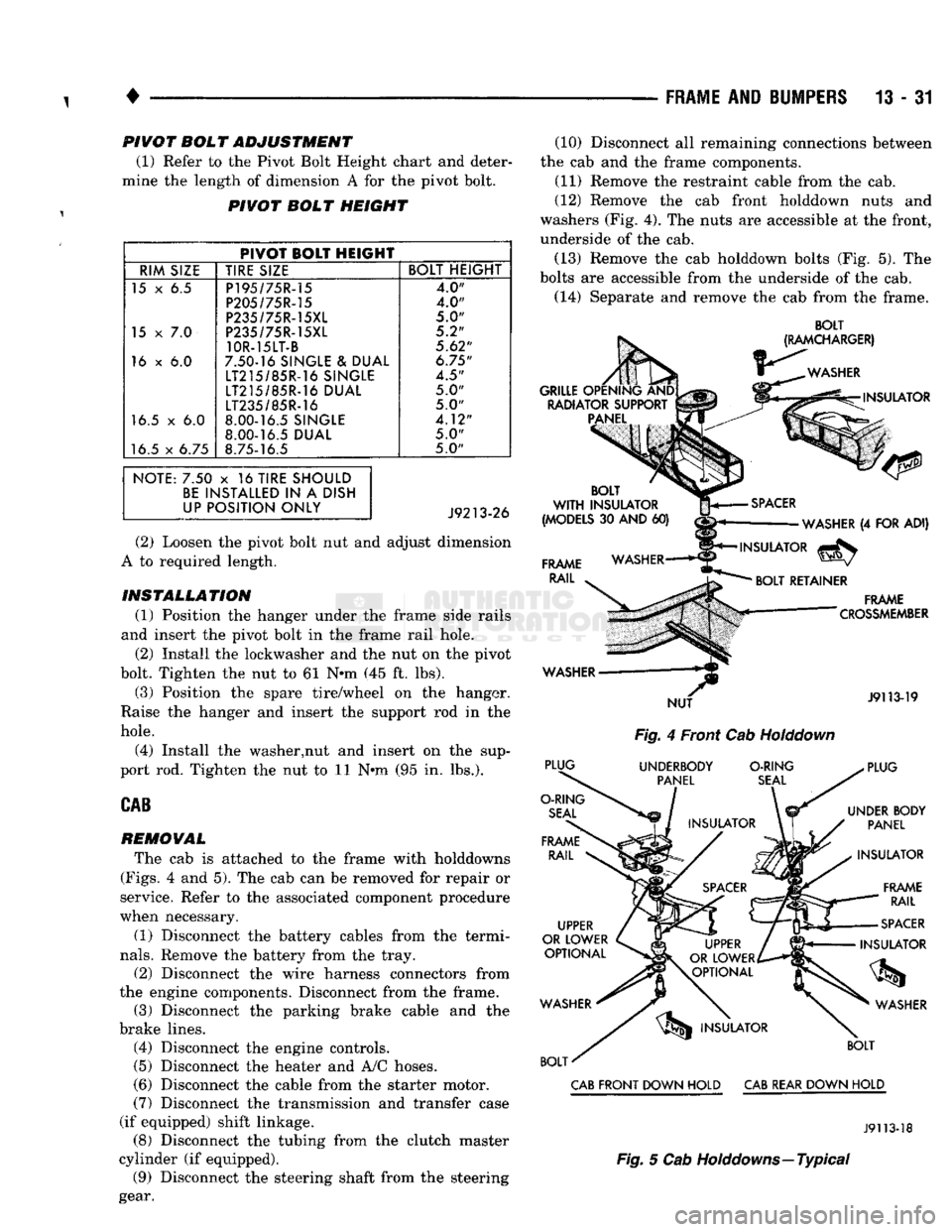
The cab is attached to the frame with holddowns
(Figs.
4 and 5). The cab can be removed for repair or
service. Refer to the associated component procedure
when necessary.
(1) Disconnect the battery cables from the termi
nals.
Remove the battery from the tray.
(2) Disconnect the wire harness connectors from
the engine components. Disconnect from the frame. (3) Disconnect the parking brake cable and the
brake lines. (4) Disconnect the engine controls.
(5)
Disconnect the heater and A/C hoses.
(6) Disconnect the cable from the starter motor.
(7)
Disconnect the transmission and transfer case
(if equipped) shift linkage. (8) Disconnect the tubing from the clutch master
cylinder (if equipped). (9) Disconnect the steering shaft from the steering
gear. (10) Disconnect all remaining connections between
the cab and the frame components. (11) Remove the restraint cable from the cab.
(12) Remove the cab front holddown nuts and
washers (Fig. 4). The nuts are accessible at the front,
underside of the cab.
(13) Remove the cab holddown bolts (Fig. 5). The
bolts are accessible from the underside of the cab.
(14) Separate and remove the cab from the frame.
BOLT
Fig.
4 Front Cab
Holddown
CAB
FRONT DOWN HOLD
CAB
REAR DOWN HOLD
J9113-18
Fig.
5 Cab Holddowns—Typical
Page 819 of 1502
13
- 32
FRAME
AND
BUMPERS
• r INSTALLATION
(1) Verify the insulators and spacers are positioned
on the frame holddown brackets (Figs. 4 and 5). (2) Position the cab on the frame.
(3) Install the cab holddown nuts and bolts (Figs. 4
and 5). Tighten the nuts to 68 N-m (50 ft. lbs.)
torque. Tighten the bolts to 81 Nnn (60 ft. lbs.)
torque. (4) Position the restraint cable ends on the cab
rear seat belt anchor bolts. Install the retaining nuts.
Tighten the nuts to 45 N-m. (33 ft. lbs.) torque.
(5) Connect the steering shaft to the steering gear.
(6) Connect the tubing to the clutch master cylin
der (if equipped).
(7) Connect the transmission and transfer case (if
equipped) shift linkage. (8) Connect the cable to the starter motor.
(9) Connect the heater and A/C hoses.
(10) Connect the engine controls.
(11) Connect the parking brake cable and the
brake lines.
(12) Connect the wire harness connectors to the
engine components and to the frame. (13) Connect all remaining items between the cab
and the frame components. (14) Install the battery in the tray. Connect the ca
bles to the terminals. (15) Inspect the installation of the cab on the
frame and verify that:
• All connecting hardware is tightened
• All fluids and lubricants are full
• All electrical, engine, drivetrain and chassis com
ponents are operational.
CARGO
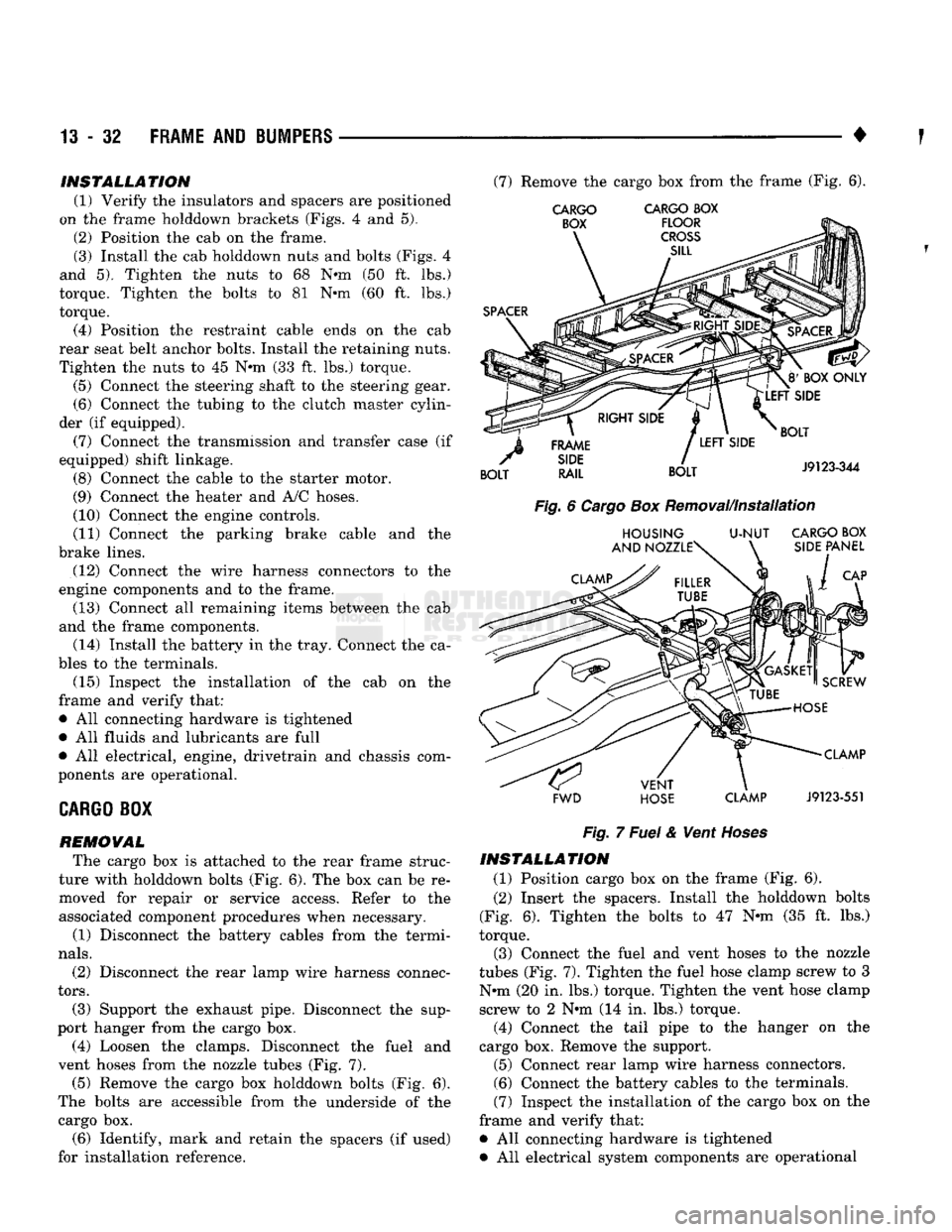
BOX REMOVAL The cargo box is attached to the rear frame struc
ture with holddown bolts (Fig. 6). The box can be re moved for repair or service access. Refer to the
associated component procedures when necessary.
(1) Disconnect the battery cables from the termi
nals.
(2) Disconnect the rear lamp wire harness connec
tors.
(3) Support the exhaust pipe. Disconnect the sup
port hanger from the cargo box. (4) Loosen the clamps. Disconnect the fuel and
vent hoses from the nozzle tubes (Fig. 7). (5) Remove the cargo box holddown bolts (Fig. 6).
The bolts are accessible from the underside of the cargo box. (6) Identify, mark and retain the spacers (if used)
for installation reference. (7) Remove the cargo box from the frame (Fig. 6).
CARGO CARGO
BOX
FWD HOSE CLAMP
J9123-551
Fig.
7
Fuel
& Vent
Hoses
INSTALLATION
(1) Position cargo box on the frame (Fig. 6).
(2) Insert the spacers. Install the holddown bolts
(Fig. 6). Tighten the bolts to 47 Nnn (35 ft. lbs.)
torque.
(3) Connect the fuel and vent hoses to the nozzle
tubes (Fig. 7). Tighten the fuel hose clamp screw to 3
Nnn (20 in. lbs.) torque. Tighten the vent hose clamp screw to 2 Nnn (14 in. lbs.) torque.
(4) Connect the tail pipe to the hanger on the
cargo box. Remove the support. (5) Connect rear lamp wire harness connectors.
(6) Connect the battery cables to the terminals.
(7) Inspect the installation of the cargo box on the
frame and verify that:
• All connecting hardware is tightened • All electrical system components are operational
Page 820 of 1502
•
FUEL
SYSTEM
14 - 1
FUEL
SYSTEM
page
ACCELERATOR
PEDAL
AND THROTTLE
CABLE
................ 25
DIESEL
FUEL
INJECTION-COMPONENT
DESCRIPTION/SYSTEM
OPERATION
76
DIESEL
FUEL
INJECTION-GENERAL
DIAGNOSIS
88
DIESEL
FUEL
INJECTION-SERVICE
PROCEDURES
....................... 106
FUEL
DELIVERY
SYSTEM-EXCEPT
DIESEL
.. 3
FUEL
DELIVERY-DIESEL
ENGINE
15
FUEL
TANKS
.... 20
page
GENERAL
INFORMATION 1
MULTI-PORT
FUEL
INJECTION (MPI)-
COMPONENT
DESCRIPTION/SYSTEM
OPERATION-EXCEPT
DIESEL
29
MULTI-PORT
FUEL
INJECTION (MPI)-
COMPONENT
REMOVAL/INSTALLATION-
EXCEPT
DIESEL
64
MULTI-PORT
FUEL
INJECTION (MPI)-
GENERAL
DIAGNOSIS-EXCEPT
DIESEL
...43
SERVICE
ADJUSTMENTS-DIESEL
122
SPECIFICATIONS
123
GENERAL INFORMATION
Throughout this group, references are made to par
ticular vehicle models by alphabetical designation or
by the particular vehicle nameplate. A chart showing a breakdown of the alphabetical designations is in
cluded in the Introduction section at the beginning of
this manual.
The 5.9L (V-8) gas powered engine will be referred
to in this group as either the: LDC (Light Duty Cy cle) or HDC (Heavy Duty Cycle) engine. The HDC engine can be easily identified by the use of an en
gine mounted air injection pump. The 3.9L/5.2L/5.9L
LDC engine will not use an air injection pump.
This Fuel System group will cover all fuel system
components for the 3.9L (V-6), 5.2L (V-8), 5.9L LDC
(V-8),
5.9L HDC (V-8) and 5.9L (in-line six cylinder)
diesel engines.
The Fuel System consists of: the fuel tank, an
electric (fuel tank mounted) fuel pump and fuel fil
ter. It also consists of fuel tubes/lines/hoses, vacuum
hoses,
throttle body and fuel injector(s).
The Fuel Delivery System consists of: the electric
fuel pump, fuel filter, fuel tubes/lines/hoses, fuel rail,
fuel injectors and fuel pressure regulator.
A Fuel Return System is used on all vehicles (all
engines) except the 5.9L (V-8) gas powered engine. On this engine, a returnless type fuel system is
used. The fuel return system consists of fuel tubes/
lines and hoses that route fuel back to the fuel tank.
The Fuel Tank Assembly consists of: the fuel
tank, filler tube, fuel gauge sending unit/electric fuel
pump module, a pressure relief/rollover valve and a
pressure-vacuum filler cap. Also to be considered part of the fuel system is the
Evaporation Control System. This is designed to
reduce the emission of fuel vapors into the atmo sphere. The description and function of the Evapora
tive Control System is found in Group 25, Emission Control Systems.
FUEL
USAGE
STATEMENT-GAS
ENGINES
Your vehicle was designed to meet all emission
regulations and provide excellent fuel economy using
high quality unleaded gasoline. Only use unleaded gasolines having a minimum posted octane of 87. If your vehicle develops occasional light spark
knock (ping) at low engine speeds, this is not harm
ful.
However, continued heavy knock at high speeds can cause damage and should be re
ported to your dealer immediately. Engine dam age as a result of heavy knock operation may not be
covered by the new vehicle warranty. In addition to using unleaded gasoline with the
proper octane rating, those that contain deter
gents,
corrosion and stability additives are rec
ommended. Using gasolines that have these additives will help improve fuel economy, reduce
emissions and maintain vehicle performance. Gener ally, premium unleaded gasolines contain more addi
tive than regular unleaded gasolines. Poor quality gasoline can cause problems such as
hard starting, stalling and stumble. If you experience
these problems, use another brand of gasoline before considering service for the vehicle.