FIAT BARCHETTA 2003 1.G Owners Manual
Manufacturer: FIAT, Model Year: 2003, Model line: BARCHETTA, Model: FIAT BARCHETTA 2003 1.GPages: 170, PDF Size: 3.55 MB
Page 151 of 170
150
ELECTRONIC ALARM
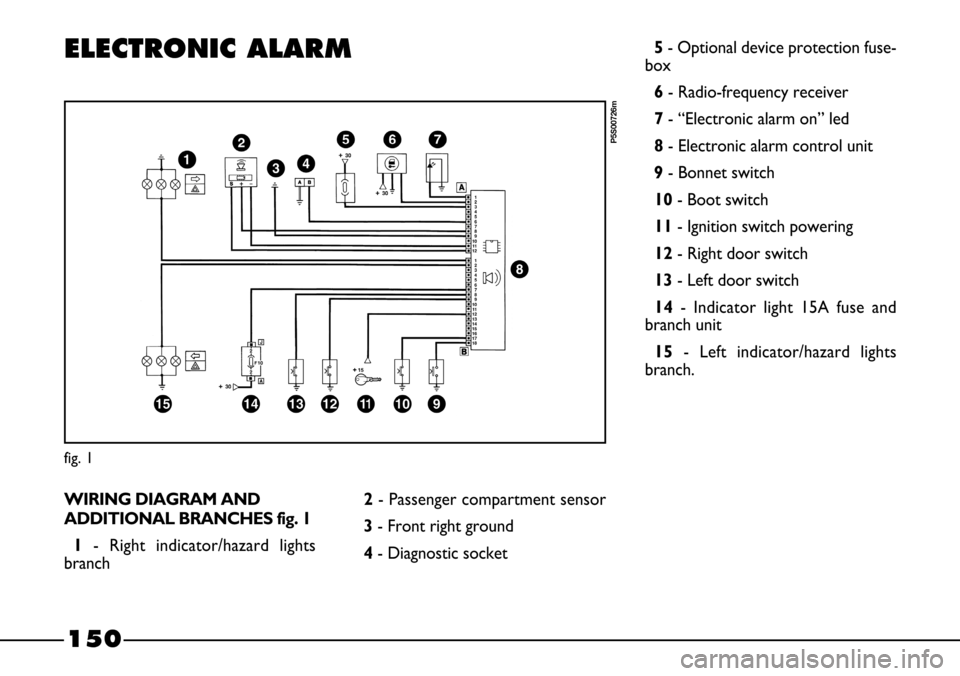
WIRING DIAGRAM AND
ADDITIONAL BRANCHES fig. 1
1- Right indicator/hazard lights
branch
fig. 1
P5S00726m
2- Passenger compartment sensor
3- Front right ground
4- Diagnostic socket5- Optional device protection fuse-
box
6- Radio-frequency receiver
7- “Electronic alarm on” led
8- Electronic alarm control unit
9- Bonnet switch
10- Boot switch
11- Ignition switch powering
12- Right door switch
13- Left door switch
14- Indicator light 15A fuse and
branch unit
15 - Left indicator/hazard lights
branch.
Page 152 of 170
151
LOCATION
OF COMPONENTS
IN THE VEHICLE fig. 2
A- Radio-frequency receiver in ceil-
ing light
B - “Bonnet open” signal switch con-
trol (adjustable cap)
C- “Bonnet open” signal switch
D- “Right door open”, “left door
open” and “boot open” signal switch
E- Electronic alarm control unit (in
the engine compartment)
F- “Electronic alarm on” warning led
G- Radio-frequency remote control
H- Passenger compartment protec-
tion sensor (located under the central
tunnel).
fig. 2
P5S10042m
Page 153 of 170
152
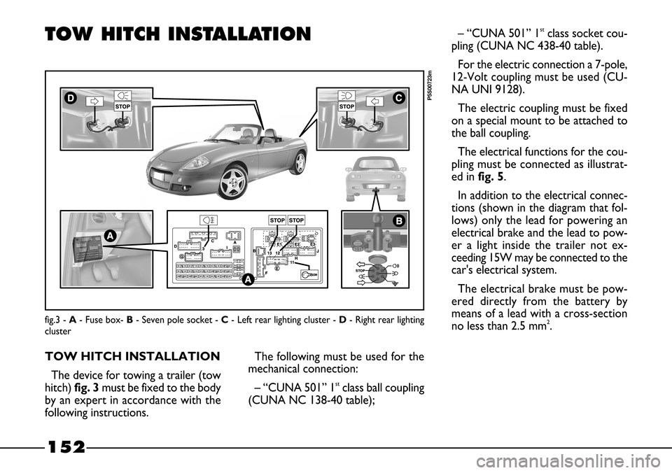
fig.3 - A- Fuse box- B- Seven pole socket - C- Left rear lighting cluster - D- Right rear lighting
cluster
P5S00723m
TOW HITCH INSTALLATION
TOW HITCH INSTALLATION
The device for towing a trailer (tow
hitch) fig. 3must be fixed to the body
by an expert in accordance with the
following instructions.The following must be used for the
mechanical connection:
– “CUNA 501” 1
stclass ball coupling
(CUNA NC 138-40 table);– “CUNA 501” 1
stclass socket cou-
pling (CUNA NC 438-40 table).
For the electric connection a 7-pole,
12-Volt coupling must be used (CU-
NA UNI 9128).
The electric coupling must be fixed
on a special mount to be attached to
the ball coupling.
The electrical functions for the cou-
pling must be connected as illustrat-
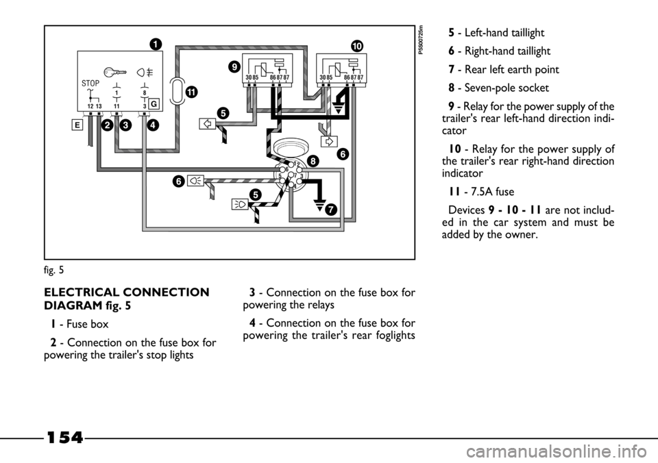
ed infig. 5.
In addition to the electrical connec-
tions (shown in the diagram that fol-
lows) only the lead for powering an
electrical brake and the lead to pow-
er a light inside the trailer not ex-
ceeding 15W may be connected to the
car's electrical system.
The electrical brake must be pow-
ered directly from the battery by
means of a lead with a cross-section
no less than 2.5 mm
2.
Page 154 of 170
153
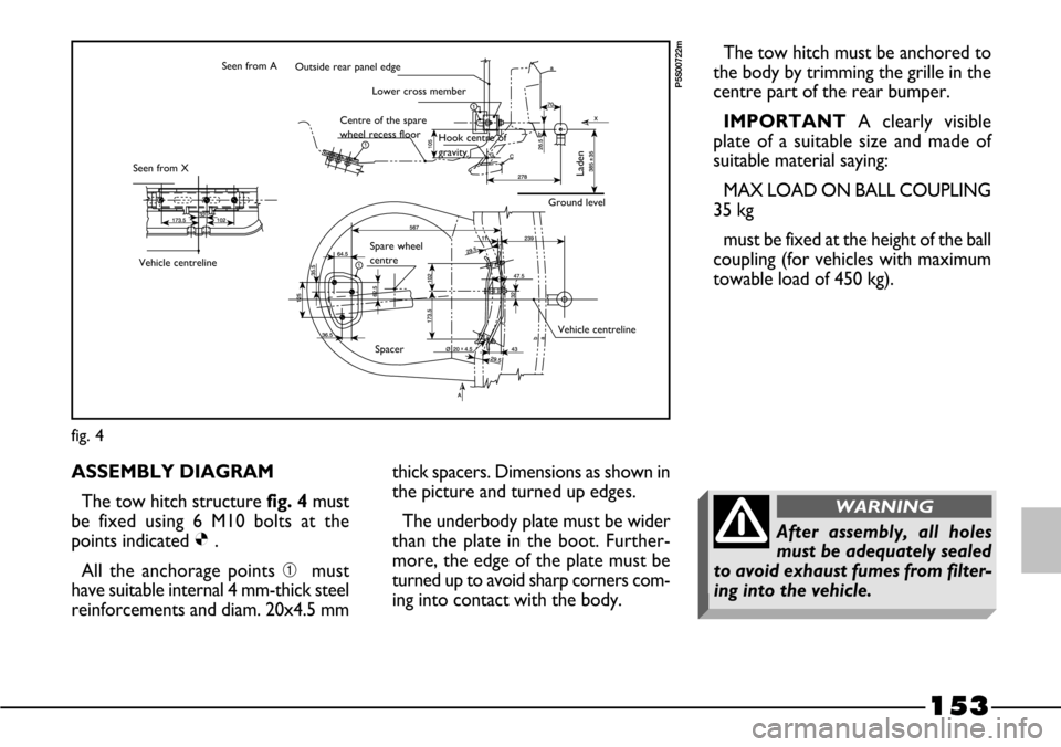
ASSEMBLY DIAGRAM
The tow hitch structure fig. 4must
be fixed using 6 M10 bolts at the
points indicated Ø.
All the anchorage points ➀must
have suitable internal 4 mm-thick steel
reinforcements and diam. 20x4.5 mmthick spacers. Dimensions as shown in
the picture and turned up edges.
The underbody plate must be wider
than the plate in the boot. Further-
more, the edge of the plate must be
turned up to avoid sharp corners com-
ing into contact with the body.
fig. 4
P5S00722m
The tow hitch must be anchored to
the body by trimming the grille in the
centre part of the rear bumper.
IMPORTANTA clearly visible
plate of a suitable size and made of
suitable material saying:
MAX LOAD ON BALL COUPLING
35 kg
must be fixed at the height of the ball
coupling (for vehicles with maximum
towable load of 450 kg).Outside rear panel edge
Lower cross member
Laden
Ground level Hook centre of
gravity Centre of the spare
wheel recess floor
Seen from X
Vehicle centreline
Vehicle centreline
Spacer Spare wheel
centre Seen from A
After assembly, all holes
must be adequately sealed
to avoid exhaust fumes from filter-
ing into the vehicle.
WARNING
Page 155 of 170
154
fig. 5
P5S00725m
ELECTRICAL CONNECTION
DIAGRAM fig. 5
1- Fuse box
2- Connection on the fuse box for
powering the trailer's stop lights3- Connection on the fuse box for
powering the relays
4- Connection on the fuse box for
powering the trailer's rear foglights5- Left-hand taillight
6- Right-hand taillight
7- Rear left earth point
8- Seven-pole socket
9 - Relay for the power supply of the
trailer's rear left-hand direction indi-
cator
10- Relay for the power supply of
the trailer's rear right-hand direction
indicator
11- 7.5A fuse
Devices9 - 10 - 11are not includ-
ed in the car system and must be
added by the owner.
Page 156 of 170
155
HARD TOP
The hard top is fitted with a heated
rear window and can be installed in
place of the hood to provide maxi-
mum comfort during winter.
The hard top is not only on offer as
an optional extra, but is also part of
the Lineaccessori Fiat line, and is
therefore available even after the car
has been purchased.
When the hard top is bought from
Lineaccessori Fiat, pin seats and fixing
screws are also supplied.The seats must be fixed to the rear
pillars that have 2 threaded holes and
can be left in place even when the hard
top is no longer used.
When the hard top is mounted for
the first time, it is necessary to adjust
the rear tie rods.You should have these operations
carried out at a Fiat Dealership.
See the chapter “Getting to know
your car” for instructions on how to
fit and remove the hard top correct-
ly.
Page 157 of 170
156
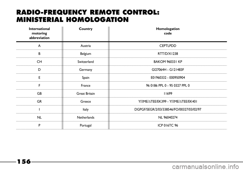
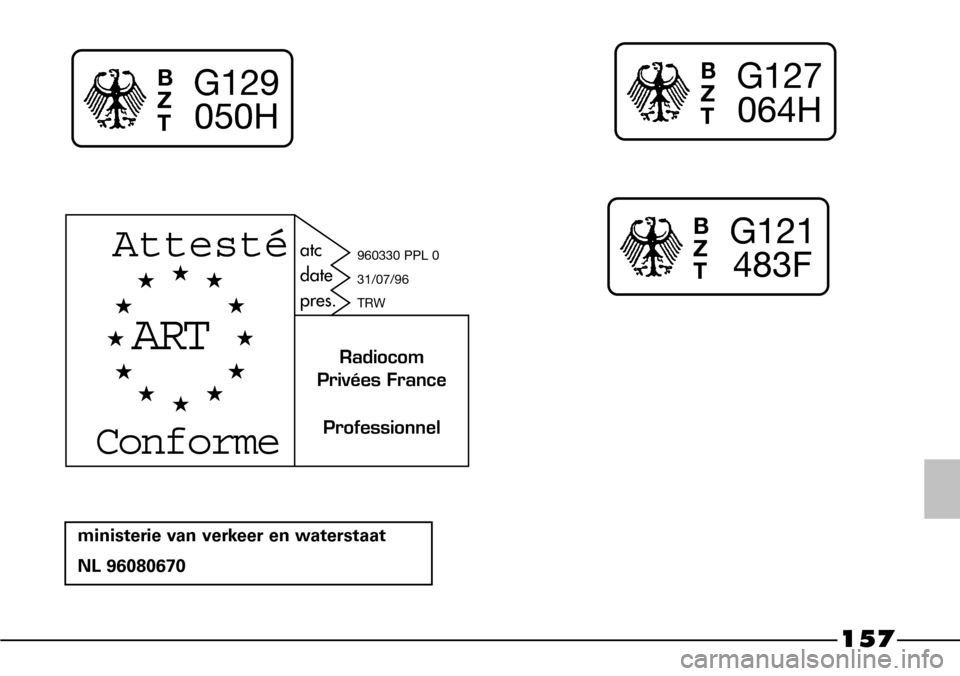
RADIO-FREQUENCY REMOTE CONTROL:
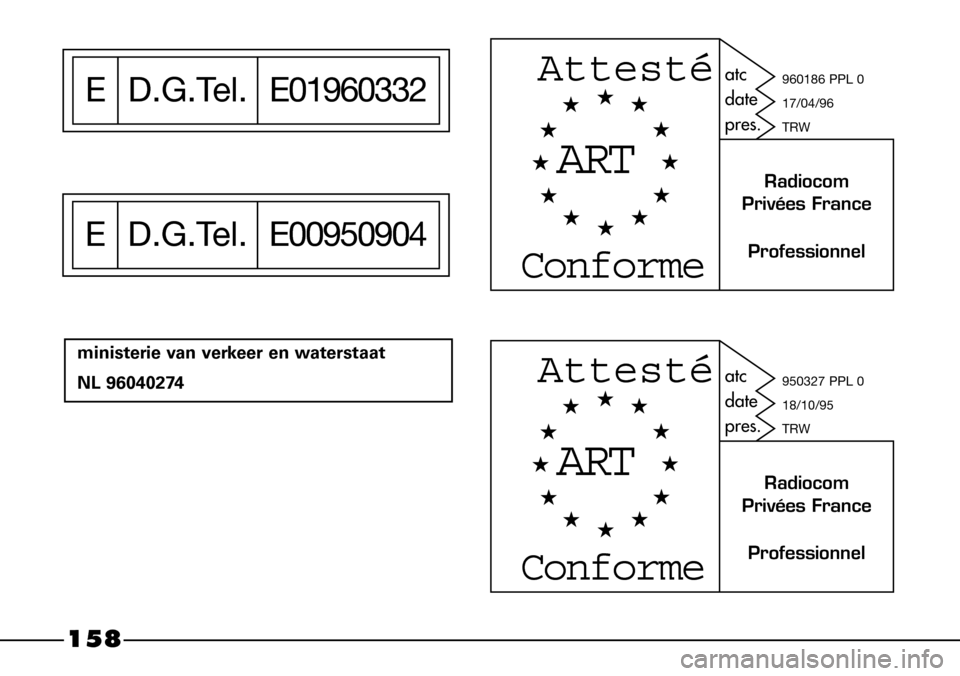
MINISTERIAL HOMOLOGATION
International Country Homologation
motoring code
abbreviation
A Austria CEPTLPDD
B Belgium RTT/D/X1238
CH Switzerland BAKOM 960331 KP
D Germany GI27064H - G121483F
E Spain E01960332 - E00950904
F France 96 0186 PPL 0 - 95 0327 PPL 0
GB Great Britain 11699
GR Greece Y∏ME/∆TEE/EK399 - Y∏ME/∆TEE/EK401
I Italy DGPGF/SEGR/2/03/338546/FO/00327/03/02/97
NLNetherlands NL 96040274
P Portugal ICP 016TC 96
Page 158 of 170
157
B
Z
TG129
050H
ministerie van verkeer en waterstaat
NL 96080670
B
Z
TG127
064H
B
Z
TG121
483F
ART
Attesté
Conforme
Professionnel atc
date
pres.
Radiocom
Privées France
960330 PPL 0
31/07/96
TRW
Page 159 of 170
158
ministerie van verkeer en waterstaat
NL 96040274
ED.G.Tel.E01960332
ED.G.Tel.E00950904
ART
Attesté
Conforme
Professionnel atc
date
pres.
Radiocom
Privées France
960186 PPL 0
17/04/96
TRW
ART
Attesté
Conforme
Professionnel atc
date
pres.
Radiocom
Privées France
950327 PPL 0
18/10/95
TRW
Page 160 of 170
159
INDEX
ABS ........................................... 56
Accessories purchased
by the owner .............................. 82
Accessory installation......... 149
Air cleaner................................... 122
Air recirculation ......................... 36
Airbags
– general information ............ 60
– switching the passenger side
airbag off .............................. 59
Ashtray ......................................... 43
Battery
– jump starting ................ 85-105
– liquid level ............................ 123
– recharging ............................. 105
Bodywork
– maintenance ......................... 130
– paint identification plate .... 137
– versions ............................... 137
Bonnet .......................................... 53
Boot
– opening/closing.................... 55
Brake fluid level .......................... 121Brake lights .................................. 96
Brakes
– fluid level............................... 121
– service and emergency
brakes .................................... 139
Bulb replacement ....................... 91
Car maintenance................. 111
Capacities ............................. 64-144
Catalytic converter .................. 66
Ceiling light.................................. 42
– bulb replacement ............... 98
Cellular phone setup................. 63
Central door locking................. 44
Cheap running ............................ 78
Children (safety) ........................ 24
Cigar lighter ................................ 43
Climate control system ............ 36
– controls................................. 36
– maintenance ......................... 130
Clutch ........................................... 139
CO
2emissions ........................... 147
Containing running costs
and pollution ........................... 76
Dashboard ................................ 7Defrosting.................................... 35
Demisting..................................... 35
Digital clock ................................ 29
Dimensions ................................ 142
Dipped-beam headlights
– controls ............................... 38
– bulb replacement ............... 93
Direction indicators
– controls ............................... 39
– front bulb replacement ..... 94
– rear bulb replacement ...... 95
– side bulb replacement ...... 95
Doors ........................................... 44
Driving your car..................... 67
Electric windows ..................... 45
Electronic alarm.................. 13-150
Electronic control units............ 125
Engine
– cooling................................... 138
– fuel feed/ignition ................. 138
– identification code .............. 136
– lubrication ............................ 138
– specifications........................ 137
Engine compartment washing . 132