key FIAT DUCATO 2006 Owner handbook (in English)
[x] Cancel search | Manufacturer: FIAT, Model Year: 2006, Model line: DUCATO, Model: FIAT DUCATO 2006Pages: 238, PDF Size: 3.29 MB
Page 18 of 238
17
SAFETY
DEVICES
CORRECT USE
OF THE
VEHICLE
WARNING
LIGHTS AND
MESSAGES
IN AN
EMERGENCY
VEHICLE
MAINTENANCE
TECHNICAL
SPECIFICATIONS
INDEX
DASHBOARD
AND CONTROLS
ENGINE OIL LEVEL GAUGE
This gauge shows the engine oil level.
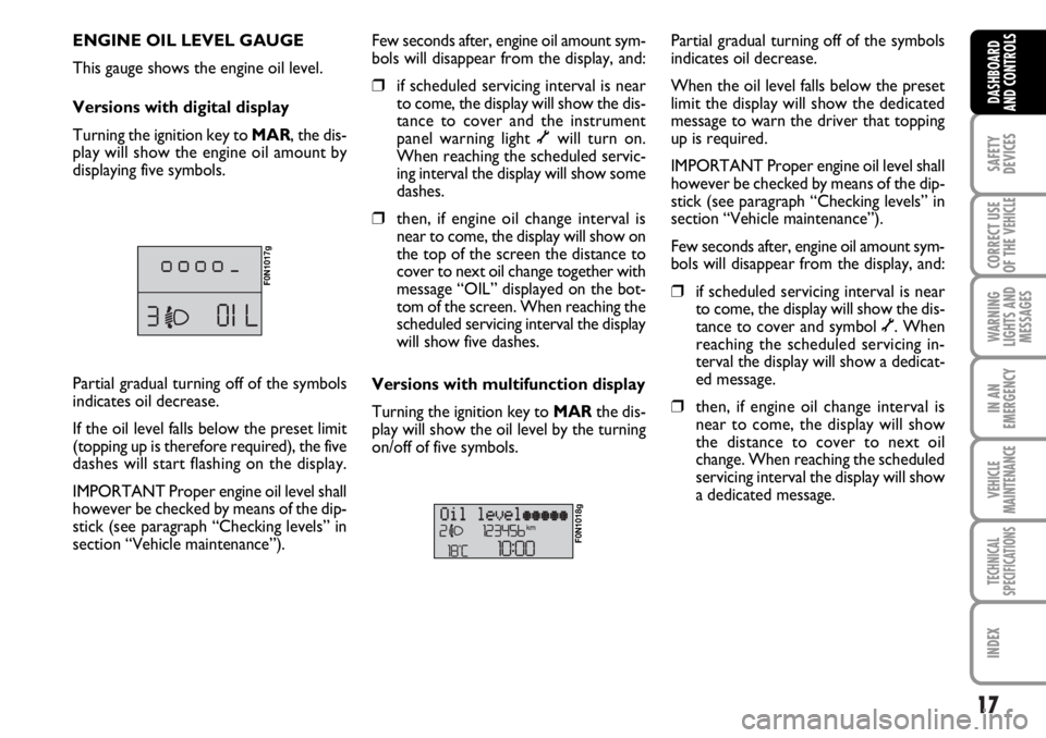
Versions with digital display
Turning the ignition key to MAR, the dis-
play will show the engine oil amount by
displaying five symbols.
F0N1017g
Few seconds after, engine oil amount sym-
bols will disappear from the display, and:
❒if scheduled servicing interval is near
to come, the display will show the dis-
tance to cover and the instrument
panel warning light õwill turn on.
When reaching the scheduled servic-
ing interval the display will show some
dashes.
❒then, if engine oil change interval is
near to come, the display will show on
the top of the screen the distance to
cover to next oil change together with
message “OIL” displayed on the bot-
tom of the screen. When reaching the
scheduled servicing interval the display
will show five dashes.
Versions with multifunction display
Turning the ignition key to MARthe dis-
play will show the oil level by the turning
on/off of five symbols.
F0N1018g
Partial gradual turning off of the symbols
indicates oil decrease.
When the oil level falls below the preset
limit the display will show the dedicated
message to warn the driver that topping
up is required.
IMPORTANT Proper engine oil level shall
however be checked by means of the dip-
stick (see paragraph “Checking levels” in
section “Vehicle maintenance”).
Few seconds after, engine oil amount sym-
bols will disappear from the display, and:
❒if scheduled servicing interval is near
to come, the display will show the dis-
tance to cover and symbol õ. When
reaching the scheduled servicing in-
terval the display will show a dedicat-
ed message.
❒then, if engine oil change interval is
near to come, the display will show
the distance to cover to next oil
change. When reaching the scheduled
servicing interval the display will show
a dedicated message. Partial gradual turning off of the symbols
indicates oil decrease.
If the oil level falls below the preset limit
(topping up is therefore required), the five
dashes will start flashing on the display.
IMPORTANT Proper engine oil level shall
however be checked by means of the dip-
stick (see paragraph “Checking levels” in
section “Vehicle maintenance”).
Page 19 of 238
18
SAFETY
DEVICES
CORRECT USE
OF THE
VEHICLE
WARNING
LIGHTS AND
MESSAGES
IN AN
EMERGENCY
VEHICLE
MAINTENANCE
TECHNICAL
SPECIFICATIONS
INDEX
DASHBOARD
AND CONTROLS
DIGITAL DISPLAY
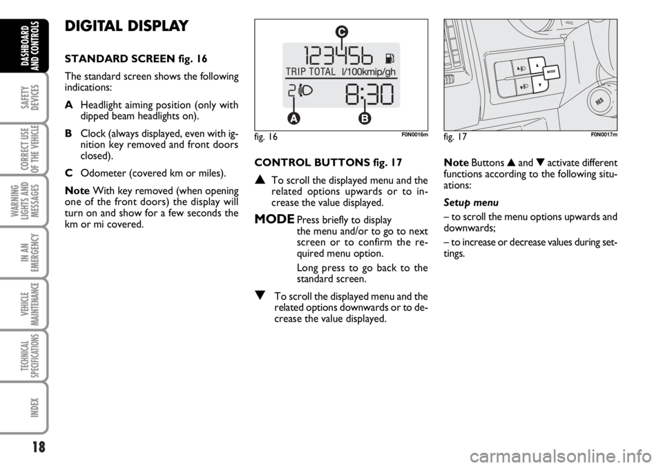
STANDARD SCREEN fig. 16
The standard screen shows the following
indications:
AHeadlight aiming position (only with
dipped beam headlights on).
BClock (always displayed, even with ig-
nition key removed and front doors
closed).
COdometer (covered km or miles).
NoteWith key removed (when opening
one of the front doors) the display will
turn on and show for a few seconds the
km or mi covered.CONTROL BUTTONS fig. 17
▲To scroll the displayed menu and the
related options upwards or to in-
crease the value displayed.
MODEPress briefly to display
the menu and/or to go to next
screen or to confirm the re-
quired menu option.
Long press to go back to the
standard screen.
▼To scroll the displayed menu and the
related options downwards or to de-
crease the value displayed.NoteButtons ▲and ▼activate different
functions according to the following situ-
ations:
Setup menu
– to scroll the menu options upwards and
downwards;
– to increase or decrease values during set-
tings.
fig. 16F0N0016mfig. 17F0N0017m
Page 25 of 238
24
SAFETY
DEVICES
CORRECT USE
OF THE
VEHICLE
WARNING
LIGHTS AND
MESSAGES
IN AN
EMERGENCY
VEHICLE
MAINTENANCE
TECHNICAL
SPECIFICATIONS
INDEX
DASHBOARD
AND CONTROLS
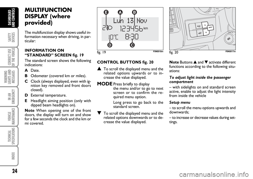
CONTROL BUTTONS fig. 20
▲To scroll the displayed menu and the
related options upwards or to in-
crease the value displayed.
MODEPress briefly to display
the menu and/or to go to next
screen or to confirm the re-
quired menu option.
Long press to go back to the
standard screen.
▼To scroll the displayed menu and the
related options downwards or to de-
crease the value displayed.
MULTIFUNCTION
DISPLAY (where
provided)
The multifunction display shows useful in-
formation necessary when driving, in par-
ticular:
INFORMATION ON
“STANDARD” SCREEN fig. 19
The standard screen shows the following
indications:
ADate.
BOdometer (covered km or miles).
CClock (always displayed, even with ig-
nition key removed and front doors
closed).
DExternal temperature.
EHeadlight aiming position (only with
dipped beam headlights on).
NoteWhen opening one of the front
doors, the display will turn on and show
for a few seconds the clock and the km or
mi covered.
fig. 19F0N0018m
NoteButtons ▲and ▼activate different
functions according to the following situ-
ations:
To adjust light inside the passenger
compartment
– with sidelights on and standard screen
active, enable to adjust the light intensity
from inside the vehicle
Setup menu
– to scroll the menu options upwards and
downwards;
– to increase or decrease values during set-
tings.
fig. 20F0N0017m
Page 32 of 238

31
SAFETY
DEVICES
CORRECT USE
OF THE
VEHICLE
WARNING
LIGHTS AND
MESSAGES
IN AN
EMERGENCY
VEHICLE
MAINTENANCE
TECHNICAL
SPECIFICATIONS
INDEX
DASHBOARD
AND CONTROLS
Adjusting the button volume
(Button Vol.)
With this function the volume of the
roger-beep accompanying the activation
of buttons MODE, ▲and ▼can be ad-
justed according to 8 levels.
To adjust the volume proceed as follows:
– briefly press button MODE: the previ-
ously set volume “level” will flash on the
display;
– press button ▲or ▼for setting;
– briefly press button MODEto go back
to the menu screen or press the button
for long to go back to the standard screen
without storing settings.S.B.R. buzzer reactivation
(Belt Buzzer)
This function can be only displayed after
Fiat Dealership has deactivated the S.B.R.
system (see paragraph “S.B.R. system” in
section “Safety devices”).
Scheduled Servicing (Service)
Through this function it is possible to dis-
play information connected to proper ve-
hicle servicing.
Proceed as follows:
– briefly press button MODE: service in
km or mi, according to previous setting,
will be displayed (see paragraph “Units”);
– briefly press button MODEto go back
to the menu screen or press the button
for long to go back to the standard screen.NoteThe “Service schedule” plans dif-
ferent service intervals according to en-
gine models; service interval is displayed
automatically, with the ignition key at
MAR, starting from 2,000 km (or 1,240
mi) from this deadline and it is shown again
every 200 km (or 124 mi). Oil change
warning messages are displayed in the
same way. Use buttons ▲and ▼to dis-
play alternately service schedule info and
engine oil change info. Below 200 km ser-
vicing indications are displayed more fre-
quently. Service indications will be dis-
played in km or mi according to previous
unit setting. When a programmed main-
tenance interval (coupon) is near to come,
turning the ignition key to MAR, the dis-
play will show the message “Service” fol-
lowed by the number of km/mi to go be-
fore vehicle servicing. Contact a Fiat Deal-
ership to carry out any service operation
provided by the “Service schedule” and to
reset the display.
Page 34 of 238

33
SAFETY
DEVICES
CORRECT USE
OF THE
VEHICLE
WARNING
LIGHTS AND
MESSAGES
IN AN
EMERGENCY
VEHICLE
MAINTENANCE
TECHNICAL
SPECIFICATIONS
INDEX
DASHBOARD
AND CONTROLS
TRIP COMPUTER
General features
The “Trip computer” displays information
(with ignition key at MAR), relating to the
operating status of the vehicle. This func-
tion comprises two separate and inde-
pendent trips: “Trip A” and “Trip B” con-
cerning the “complete mission” of the ve-
hicle (journey).
Both functions are resettable (reset - start
of new mission).
“Trip A” shall be used to display the fig-
ures relating to:
– Range
– Trip distance
– Average consumption
– Instant consumption
– Average speed
– Travel time (driving time).“Trip B”, available on multifunction display
only, shall be used to display the figures
relating to:
– Trip distance B
– Average consumption B
– Average speed B
– Travel time B (driving time).
Note“Trip B” function can be excluded
(see paragraph “Trip B On/Off”). “Range”
and “Instant consumption” cannot be re-
set.
Values displayed
Range
This value shows the distance in km (or
mi) that the vehicle can still cover before
needing fuel, assuming that driving condi-
tions are kept unvaried. The display will
show “----” in the following cases:
– value lower than 50 km (or 30 mi)
– vehicle left parked with engine running
for long.
Trip distance
This value shows the distance covered
from the start of the new mission. Exit Menu
This is the last function that closes the cir-
cular setting cycle listed in the initial menu
screen.
Briefly press button MODEto go back to
the standard screen without storing set-
tings.
Press button ▼to return to the first menu
option (Speed Beep).
Page 35 of 238
34
SAFETY
DEVICES
CORRECT USE
OF THE
VEHICLE
WARNING
LIGHTS AND
MESSAGES
IN AN
EMERGENCY
VEHICLE
MAINTENANCE
TECHNICAL
SPECIFICATIONS
INDEX
DASHBOARD
AND CONTROLS
Average consumption
This value shows the average consump-
tion from the start of the new mission.
Instant consumption
This value shows instant fuel consumption
(this value is updated second by second).
If parking the vehicle with engine on,
the display will show “----”.
Average speed
This value shows the vehicle average
speed as a function of the overall time
elapsed since the start of the new mission.
Travel time
This value shows the time elapsed since
the start of the new mission.
IMPORTANT Lacking information, Trip
computer values are displayed with “----”.
When normal operating condition is re-
set, calculation of different units will
restart regularly. Values displayed before
the failure will not be reset.
fig. 22F0N0019m
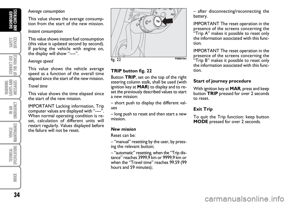
TRIP button fig. 22
Button TRIP, set on the top of the right
steering column stalk, shall be used (with
ignition key at MAR) to display and to re-
set the previously described values to start
a new mission:
– short push to display the different val-
ues
– long push to reset and then start a new
mission.
New mission
Reset can be:
– “manual” resetting by the user, by press-
ing the relevant button;
– “automatic” resetting, when the “Trip dis-
tance” reaches 3999,9 km or 9999,9 km or
when the “Travel time” reaches 99.59 (99
hours and 59 minutes);– after disconnecting/reconnecting the
battery.
IMPORTANT The reset operation in the
presence of the screens concerning the
“Trip A” makes it possible to reset only
the information associated with this func-
tion.
IMPORTANT The reset operation in the
presence of the screens concerning the
“Trip B” makes it possible to reset only
the information associated with this func-
tion.
Start of journey procedure
With ignition key at MAR, press and keep
button TRIPpressed for over 2 seconds
to reset.
Exit Trip
To quit the Trip function: keep button
MODEpressed for over 2 seconds.
Page 42 of 238
41
SAFETY
DEVICES
CORRECT USE
OF THE
VEHICLE
WARNING
LIGHTS AND
MESSAGES
IN AN
EMERGENCY
VEHICLE
MAINTENANCE
TECHNICAL
SPECIFICATIONS
INDEX
DASHBOARD
AND CONTROLS
Folding
When required (for example when the
mirror causes difficulty in narrow spaces)
it is possible to fold the mirror moving it
from position 1-fig. 35to position 2.
Powered folding
(where provided)
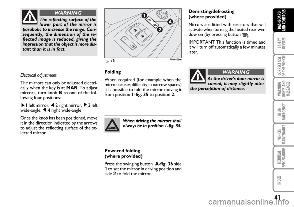
Press the swinging button A-fig. 36side
1to set the mirror in driving position and
side 2to fold the mirror.When driving the mirrors shall
always be in position 1-fig. 35.
As the driver’s door mirror is
curved, it may slightly alter
the perception of distance.
WARNING
Demisting/defrosting
(where provided)
Mirrors are fitted with resistors that will
activate when turning the heated rear win-
dow on (by pressing button
().
IMPORTANT This function is timed and
it will turn off automatically a few minutes
later. The reflecting surface of the
lower part of the mirror is
parabolic to increase the range. Con-
sequently, the dimension of the re-
flected image is reduced, giving the
impression that the object is more dis-
tant than it is in fact.
WARNING
Electrical adjustment
The mirrors can only be adjusted electri-
cally when the key is at MAR. To adjust
mirrors, turn knob Bto one of the fol-
lowing four positions:
ÿ1 left mirror, ⁄2 right mirror, ¤3 left
wide-angle, Ÿ4 right wide-angle
Once the knob has been positioned, move
it in the direction indicated by the arrows
to adjust the reflecting surface of the se-
lected mirror.
fig. 36F0N0159m
Page 59 of 238
58
SAFETY
DEVICES
CORRECT USE
OF THE
VEHICLE
WARNING
LIGHTS AND
MESSAGES
IN AN
EMERGENCY
VEHICLE
MAINTENANCE
TECHNICAL
SPECIFICATIONS
INDEX
DASHBOARD
AND CONTROLS
EXTERNAL LIGHTS
The left-hand stalk operates most of the
external lights.
The external lights can only be switched
on when the ignition key is at ON.
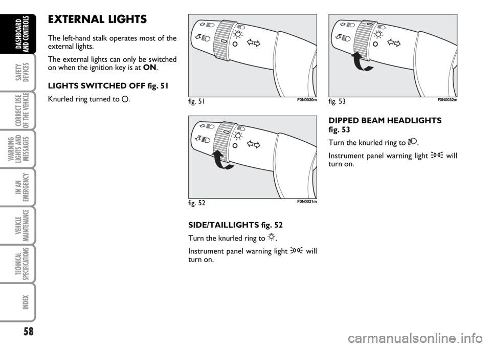
LIGHTS SWITCHED OFF fig. 51
Knurled ring turned to
å.
fig. 51F0N0030m
fig. 52F0N0031m
fig. 53F0N0032m
SIDE/TAILLIGHTS fig. 52
Turn the knurled ring to
6.
Instrument panel warning light 3will
turn on.DIPPED BEAM HEADLIGHTS
fig. 53
Turn the knurled ring to
2.
Instrument panel warning light 3will
turn on.
Page 61 of 238
60
SAFETY
DEVICES
CORRECT USE
OF THE
VEHICLE
WARNING
LIGHTS AND
MESSAGES
IN AN
EMERGENCY
VEHICLE
MAINTENANCE
TECHNICAL
SPECIFICATIONS
INDEX
DASHBOARD
AND CONTROLS
“FOLLOW ME HOME”
DEVICE
This function allows the illumination of the
space in front of the vehicle for a preset
period of time.
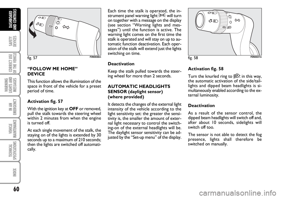
Activation fig. 57
With the ignition key at OFFor removed,
pull the stalk towards the steering wheel
within 2 minutes from when the engine
is turned off.
At each single movement of the stalk, the
staying on of the lights is extended by 30
seconds up to a maximum of 210 seconds;
then the lights are switched off automati-
cally. Each time the stalk is operated, the in-
strument panel warning light 3will turn
on together with a message on the display
(see section “Warning lights and mes-
sages”) until the function is active. The
warning light comes on the first time the
stalk is operated and will stay on up to au-
tomatic function deactivation. Each oper-
ation of the stalk will extend just the lights
switching on time.
Deactivation
Keep the stalk pulled towards the steer-
ing wheel for more than 2 seconds.
AUTOMATIC HEADLIGHTS
SENSOR (daylight sensor)
(where provided)
It detects the changes of the external light
intensity of the vehicle according to the
light sensitivity set: the greater the sensi-
tivity is, the smaller the amount of exter-
nal light necessary to control the switch-
ing-on of the external headlights will be.
The daylight sensor sensitivity can be ad-
justed by the “Set-up menu” of the display.Activation fig. 58
Turn the knurled ring to
2A:in this way,
the automatic activation of the side/tail-
lights and dipped beam headlights is si-
multaneously enabled according to the ex-
ternal luminosity.
Deactivation
As a result of the sensor control, the
dipped beam headlights will switch off and,
after about 10 seconds, sidelights will
switch off too.
The sensor is not able to detect the fog
presence, lights shall therefore be
switched on manually.
fig. 57F0N0036mfig. 58F0N0037m
Page 62 of 238
61
SAFETY
DEVICES
CORRECT USE
OF THE
VEHICLE
WARNING
LIGHTS AND
MESSAGES
IN AN
EMERGENCY
VEHICLE
MAINTENANCE
TECHNICAL
SPECIFICATIONS
INDEX
DASHBOARD
AND CONTROLS
WINDOW WASHING
WINDSCREEN WASHER/
WIPER
This device can only work when the igni-
tion key is at ON.
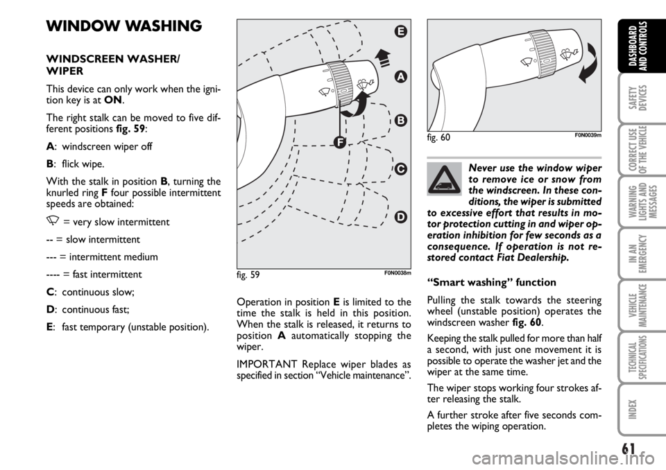
The right stalk can be moved to five dif-
ferent positions fig. 59:
A: windscreen wiper off
B: flick wipe.
With the stalk in position B, turning the
knurled ring Ffour possible intermittent
speeds are obtained:
,= very slow intermittent
-- = slow intermittent
--- = intermittent medium
---- = fast intermittent
C: continuous slow;
D: continuous fast;
E: fast temporary (unstable position).Operation in position Eis limited to the
time the stalk is held in this position.
When the stalk is released, it returns to
position Aautomatically stopping the
wiper.
IMPORTANT Replace wiper blades as
specified in section “Vehicle maintenance”.Never use the window wiper
to remove ice or snow from
the windscreen. In these con-
ditions, the wiper is submitted
to excessive effort that results in mo-
tor protection cutting in and wiper op-
eration inhibition for few seconds as a
consequence. If operation is not re-
stored contact Fiat Dealership.
“Smart washing” function
Pulling the stalk towards the steering
wheel (unstable position) operates the
windscreen washer fig. 60.
Keeping the stalk pulled for more than half
a second, with just one movement it is
possible to operate the washer jet and the
wiper at the same time.
The wiper stops working four strokes af-
ter releasing the stalk.
A further stroke after five seconds com-
pletes the wiping operation.
fig. 59F0N0038m
fig. 60F0N0039m