key FIAT DUCATO 2006 Owner handbook (in English)
[x] Cancel search | Manufacturer: FIAT, Model Year: 2006, Model line: DUCATO, Model: FIAT DUCATO 2006Pages: 238, PDF Size: 3.29 MB
Page 63 of 238
62
SAFETY
DEVICES
CORRECT USE
OF THE
VEHICLE
WARNING
LIGHTS AND
MESSAGES
IN AN
EMERGENCY
VEHICLE
MAINTENANCE
TECHNICAL
SPECIFICATIONS
INDEX
DASHBOARD
AND CONTROLS
RAIN SENSOR
(where provided)
The rain sensor is located behind the dri-
ving mirror in contact with the windscreen
and has the purpose of automatically ad-
just, during the intermittent operation, the
frequency of the windscreen wiper
strokes as to the rain intensity.
IMPORTANT Keep clean the glass in the
sensor area.
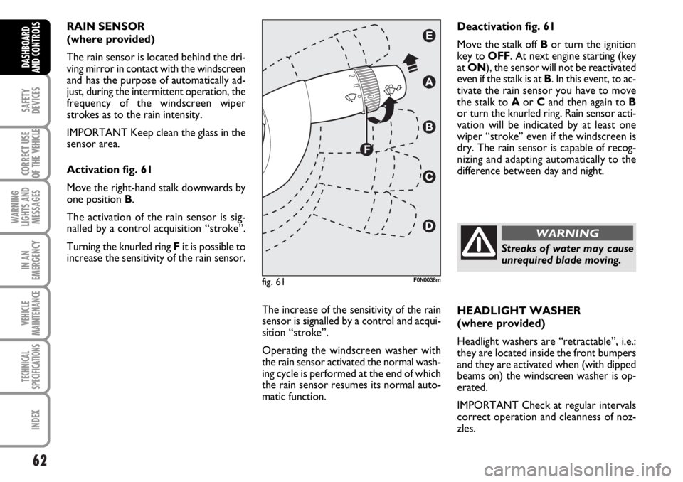
Activation fig. 61
Move the right-hand stalk downwards by
one position B.
The activation of the rain sensor is sig-
nalled by a control acquisition “stroke”.
Turning the knurled ring Fit is possible to
increase the sensitivity of the rain sensor.
The increase of the sensitivity of the rain
sensor is signalled by a control and acqui-
sition “stroke”.
Operating the windscreen washer with
the rain sensor activated the normal wash-
ing cycle is performed at the end of which
the rain sensor resumes its normal auto-
matic function.HEADLIGHT WASHER
(where provided)
Headlight washers are “retractable”, i.e.:
they are located inside the front bumpers
and they are activated when (with dipped
beams on) the windscreen washer is op-
erated.
IMPORTANT Check at regular intervals
correct operation and cleanness of noz-
zles. Deactivation fig. 61
Move the stalk off Bor turn the ignition
key to OFF. At next engine starting (key
at ON), the sensor will not be reactivated
even if the stalk is at B. In this event, to ac-
tivate the rain sensor you have to move
the stalk to Aor Cand then again to B
or turn the knurled ring. Rain sensor acti-
vation will be indicated by at least one
wiper “stroke” even if the windscreen is
dry. The rain sensor is capable of recog-
nizing and adapting automatically to the
difference between day and night.
fig. 61F0N0038m
Streaks of water may cause
unrequired blade moving.
WARNING
Page 66 of 238
65
SAFETY
DEVICES
CORRECT USE
OF THE
VEHICLE
WARNING
LIGHTS AND
MESSAGES
IN AN
EMERGENCY
VEHICLE
MAINTENANCE
TECHNICAL
SPECIFICATIONS
INDEX
DASHBOARD
AND CONTROLS
CEILING LIGHTS
FRONT CEILING LIGHT WITH
SPOT LIGHTS
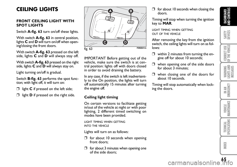
Switch A-fig. 63turn on/off these lights.
With switch A-fig. 63in central position,
lights Cand Dwill turn on/off when open-
ing/closing the front doors.
With switch A-fig. 63pressed on the left
side, lights Cand Dwill always stay off.
With switch A-fig. 63pressed on the right
side, lights Cand Dwill always stay on.
Light turning on/off is gradual.
Switch B-fig. 63performs the spot func-
tion; with light off, it will turn on:
❒light Cif pressed on the left side;
❒light Dif pressed on the right side.IMPORTANT Before getting out of the
vehicle, make sure the switch is at cen-
tral position: lights off with doors closed
in order to avoid draining the battery.
In any case, if the switch is left inadvertent-
ly to the On position, the lights will turn
off automatically 15 minutes after turning
the engine off.
Ceiling light timing
On certain versions to facilitate getting
in/out of the vehicle at night or with poor
lighting, 2 different timed switching on
modes have been provided.
LIGHT TIMING WHEN GETTING
INTO THE VEHICLE
Lights will turn on as follows:
❒for about 10 seconds when opening
front doors;
❒for about 3 minutes when opening one
of the side doors;
❒for about 10 seconds when closing the
doors.
Timing will stop when turning the ignition
key to MAR.
LIGHT TIMING WHEN GETTING
OUT OF THE VEHICLE
After removing the key from the ignition
switch, the ceiling lights will turn on as fol-
lows:
❒within 2 minutes from turning the en-
gine off for about 10 seconds;
❒when opening one of the side doors
for about 3 minutes;
❒when closing one of the doors for
about 10 seconds.
Timing will stop automatically when lock-
ing the doors.
fig. 63F0N0041m
Page 67 of 238
66
SAFETY
DEVICES
CORRECT USE
OF THE
VEHICLE
WARNING
LIGHTS AND
MESSAGES
IN AN
EMERGENCY
VEHICLE
MAINTENANCE
TECHNICAL
SPECIFICATIONS
INDEX
DASHBOARD
AND CONTROLS
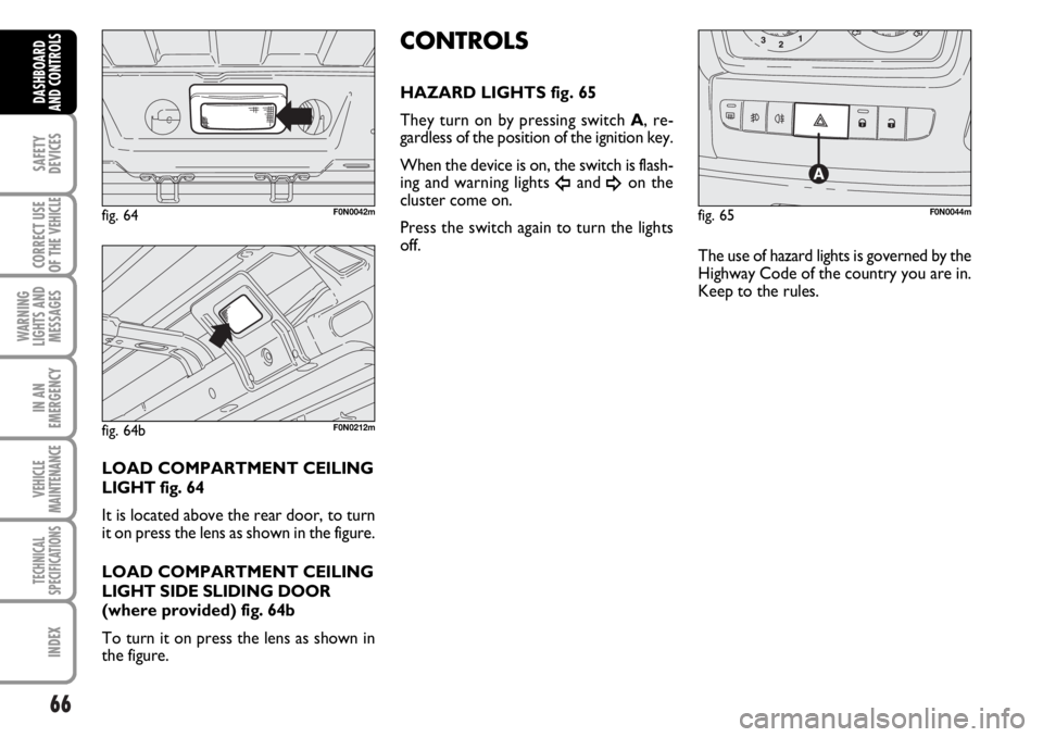
LOAD COMPARTMENT CEILING
LIGHT fig. 64
It is located above the rear door, to turn
it on press the lens as shown in the figure.
LOAD COMPARTMENT CEILING
LIGHT SIDE SLIDING DOOR
(where provided) fig. 64b
To turn it on press the lens as shown in
the figure.
CONTROLS
HAZARD LIGHTS fig. 65
They turn on by pressing switch A, re-
gardless of the position of the ignition key.
When the device is on, the switch is flash-
ing and warning lights
Îand ¥on the
cluster come on.
Press the switch again to turn the lights
off.
fig. 64F0N0042mfig. 65F0N0044m
The use of hazard lights is governed by the
Highway Code of the country you are in.
Keep to the rules.
fig. 64bF0N0212m
Page 68 of 238
67
SAFETY
DEVICES
CORRECT USE
OF THE
VEHICLE
WARNING
LIGHTS AND
MESSAGES
IN AN
EMERGENCY
VEHICLE
MAINTENANCE
TECHNICAL
SPECIFICATIONS
INDEX
DASHBOARD
AND CONTROLS
fig. 66F0N0045m
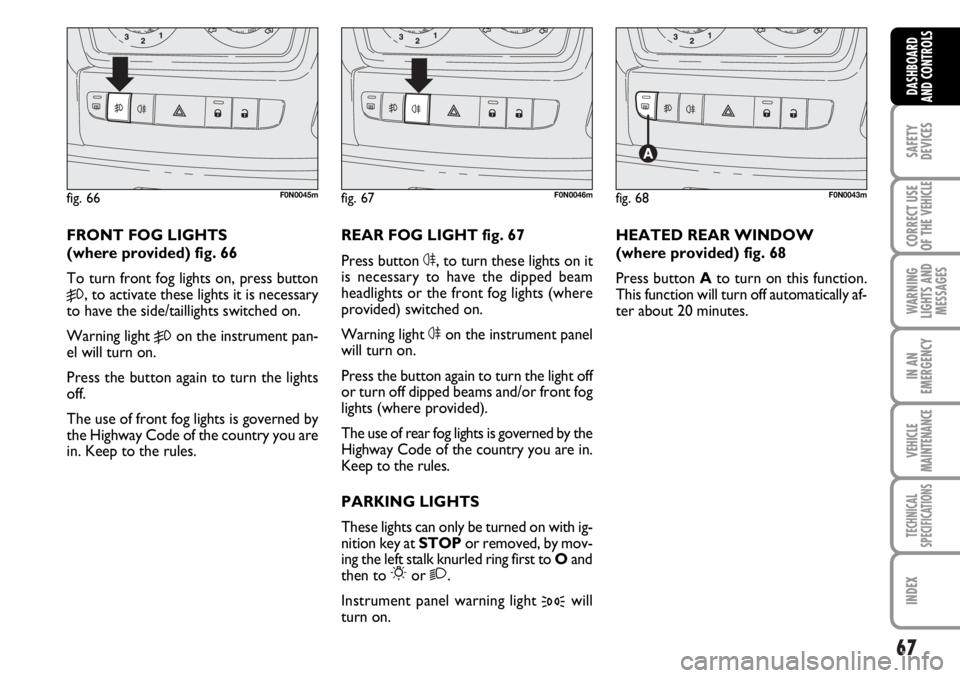
FRONT FOG LIGHTS
(where provided) fig. 66
To turn front fog lights on, press button
5, to activate these lights it is necessary
to have the side/taillights switched on.
Warning light
5on the instrument pan-
el will turn on.
Press the button again to turn the lights
off.
The use of front fog lights is governed by
the Highway Code of the country you are
in. Keep to the rules.REAR FOG LIGHT fig. 67
Press button 4, to turn these lights on it
is necessary to have the dipped beam
headlights or the front fog lights (where
provided) switched on.
Warning light 4on the instrument panel
will turn on.
Press the button again to turn the light off
or turn off dipped beams and/or front fog
lights (where provided).
The use of rear fog lights is governed by the
Highway Code of the country you are in.
Keep to the rules.
PARKING LIGHTS
These lights can only be turned on with ig-
nition key at STOPor removed, by mov-
ing the left stalk knurled ring first to Oand
then to
6or 2.
Instrument panel warning light
3will
turn on.
fig. 67F0N0046mfig. 68F0N0043m
HEATED REAR WINDOW
(where provided) fig. 68
Press button Ato turn on this function.
This function will turn off automatically af-
ter about 20 minutes.
Page 69 of 238
68
SAFETY
DEVICES
CORRECT USE
OF THE
VEHICLE
WARNING
LIGHTS AND
MESSAGES
IN AN
EMERGENCY
VEHICLE
MAINTENANCE
TECHNICAL
SPECIFICATIONS
INDEX
DASHBOARD
AND CONTROLS
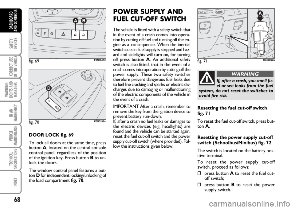
DOOR LOCK fig. 69
To lock all doors at the same time, press
button A, located on the central console
control panel, regardless of the position
of the ignition key. Press button Bto un-
lock the doors.
The window control panel features a but-
ton Dfor independent locking/unlocking of
the load compartment fig. 70.
POWER SUPPLY AND
FUEL CUT-OFF SWITCH
The vehicle is fitted with a safety switch that
in the event of a crash comes into opera-
tion by cutting off fuel and turning off the en-
gine as a consequence. When the inertial
switch cuts in, fuel supply is stopped and haz-
ard and sidelights will turn on, for turning
off press button A. An additional safety
switch is also fitted, that in the event of a
crash comes into operation by cutting off the
power supply. These two safety switches
therefore prevent dangerous fuel leaks due
to fuel line cracking and sparks or electric dis-
charges due to damaging or malfunctioning
of the electric components of the vehicle in
the event of a crash.
IMPORTANT After a crash, remember to
remove the key from the ignition device to
prevent battery run-down.
If, after a crash no fuel leaks or damages to
the electric devices (e.g. headlights) are
found and the vehicle can be started again,
reset the fuel cut-off switch and the power
supply cut-off switch (where provided). Fol-
low the instructions given below.
fig. 69F0N0047mfig. 71F0N0048m
If, after a crash, you smell fu-
el or see leaks from the fuel
system, do not reset the switches to
avoid fire risk.
WARNING
Resetting the fuel cut-off switch
fig. 71
To reset the fuel cut-off switch, press but-
ton A.
Resetting the power supply cut-off
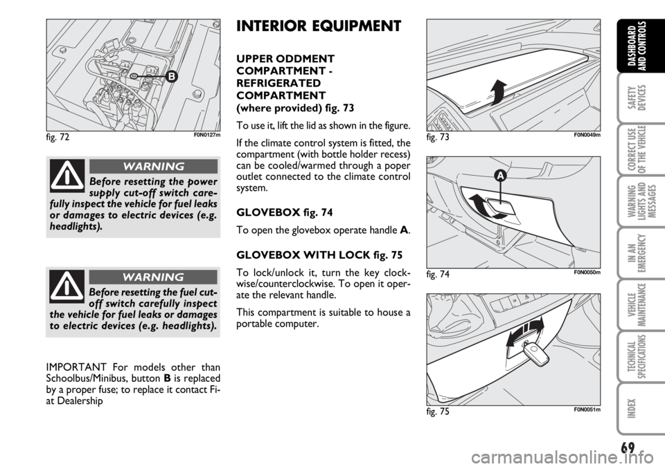
switch (Schoolbus/Minibus) fig. 72
The switch is located on the battery pos-
itive terminal.
To reset the power supply cut-off
switch, proceed as follows:
❒press button Ato reset the fuel cut-
off switch;
❒press button Bto reset the power
supply switch.
fig. 70F0N0132m
Page 70 of 238
69
SAFETY
DEVICES
CORRECT USE
OF THE
VEHICLE
WARNING
LIGHTS AND
MESSAGES
IN AN
EMERGENCY
VEHICLE
MAINTENANCE
TECHNICAL
SPECIFICATIONS
INDEX
DASHBOARD
AND CONTROLS
fig. 72F0N0127m
fig. 74F0N0050m
fig. 73F0N0049m
fig. 75F0N0051m
INTERIOR EQUIPMENT
UPPER ODDMENT
COMPARTMENT -
REFRIGERATED
COMPARTMENT
(where provided) fig. 73
To use it, lift the lid as shown in the figure.
If the climate control system is fitted, the
compartment (with bottle holder recess)
can be cooled/warmed through a poper
outlet connected to the climate control
system.
GLOVEBOX fig. 74
To open the glovebox operate handle A.
GLOVEBOX WITH LOCK fig. 75
To lock/unlock it, turn the key clock-
wise/counterclockwise. To open it oper-
ate the relevant handle.
This compartment is suitable to house a
portable computer.
Before resetting the power
supply cut-off switch care-
fully inspect the vehicle for fuel leaks
or damages to electric devices (e.g.
headlights).
WARNING
Before resetting the fuel cut-
off switch carefully inspect
the vehicle for fuel leaks or damages
to electric devices (e.g. headlights).
WARNING
IMPORTANT For models other than
Schoolbus/Minibus, button Bis replaced
by a proper fuse; to replace it contact Fi-
at Dealership
Page 72 of 238
71
SAFETY
DEVICES
CORRECT USE
OF THE
VEHICLE
WARNING
LIGHTS AND
MESSAGES
IN AN
EMERGENCY
VEHICLE
MAINTENANCE
TECHNICAL
SPECIFICATIONS
INDEX
DASHBOARD
AND CONTROLS
fig. 80F0N0054m
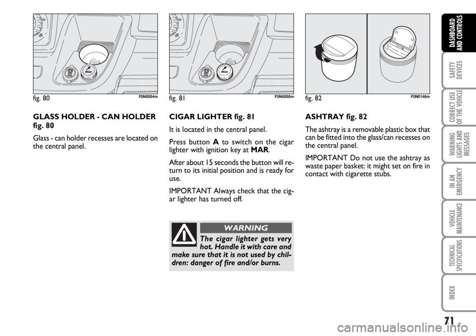
GLASS HOLDER - CAN HOLDER
fig. 80
Glass - can holder recesses are located on
the central panel. CIGAR LIGHTER fig. 81
It is located in the central panel.
Press button Ato switch on the cigar
lighter with ignition key at MAR.
After about 15 seconds the button will re-
turn to its initial position and is ready for
use.
IMPORTANT Always check that the cig-
ar lighter has turned off.ASHTRAY fig. 82
The ashtray is a removable plastic box that
can be fitted into the glass/can recesses on
the central panel.
IMPORTANT Do not use the ashtray as
waste paper basket: it might set on fire in
contact with cigarette stubs.
fig. 81F0N0055m
The cigar lighter gets very
hot. Handle it with care and
make sure that it is not used by chil-
dren: danger of fire and/or burns.
WARNING
fig. 82F0N0146m
Page 77 of 238
76
SAFETY
DEVICES
CORRECT USE
OF THE
VEHICLE
WARNING
LIGHTS AND
MESSAGES
IN AN
EMERGENCY
VEHICLE
MAINTENANCE
TECHNICAL
SPECIFICATIONS
INDEX
DASHBOARD
AND CONTROLS
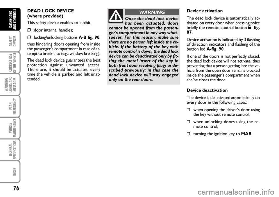
DEAD LOCK DEVICE
(where provided)
This safety device enables to inhibit:
❒door internal handles;
❒locking/unlocking buttons A-B fig. 90;
thus hindering doors opening from inside
the passenger’s compartment in case of at-
tempt to break-into (e.g.: window breaking).
The dead lock device guarantees the best
protection against unwanted access.
Therefore, it should be actuated every
time the vehicle is parked and left unat-
tended.
Once the dead lock device
has been actuated, doors
cannot be opened from the passen-
ger’s compartment in any way what-
soever. For this reason, make sure
there are no person left inside the ve-
hicle. If the battery of the key with
remote control is down, the dead lock
device can be deactivated only by fit-
ting the metal insert of the key in
both front door revolving plugs as de-
scribed previously: in this case the
dead lock device will stay engaged
only on the rear doors.
WARNINGDevice activation
The dead lock device is automatically ac-
tivated on every door when pressing twice
briefly the remote control button
Ø, fig.
87.
Device activation is indicated by 3 flashing
of direction indicators and flashing of the
button led A-fig. 90.
If one of the doors is not perfectly closed,
the dead lock device will not activate, thus
preventing that a person getting into the ve-
hicle from the open door remains blocked
inside the passenger’s compartment when
she/he closes the door.
Device deactivation
The device is deactivated automatically on
every door in the following cases:
❒when opening the driver’s door using
the key without remote control;
❒when unlocking doors using the re-
mote control;
❒turning the ignition key to MAR.
Page 79 of 238
78
SAFETY
DEVICES
CORRECT USE
OF THE
VEHICLE
WARNING
LIGHTS AND
MESSAGES
IN AN
EMERGENCY
VEHICLE
MAINTENANCE
TECHNICAL
SPECIFICATIONS
INDEX
DASHBOARD
AND CONTROLS
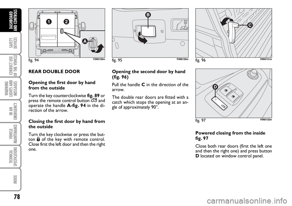
fig. 94F0N0129mfig. 95F0N0130mfig. 96F0N0131m
REAR DOUBLE DOOR
Opening the first door by hand
from the outside
Turn the key counterclockwise fig. 89or
press the remote control button ∞and
operate the handleA-fig. 94in the di-
rection of the arrow.
Closing the first door by hand from
the outside
Turn the key clockwise or press the but-
ton Áof the key with remote control.
Close first the left door and then the right
one. Opening the second door by hand
(fig. 96)
Pull the handle Cin the direction of the
arrow.
The double rear doors are fitted with a
catch which stops the opening at an an-
gle of approximately 90°.
Powered closing from the inside
fig. 97
Close both rear doors (first the left one
and then the right one) and press button
Dlocated on window control panel.
fig. 97F0N0132m
Page 80 of 238

79
SAFETY
DEVICES
CORRECT USE
OF THE
VEHICLE
WARNING
LIGHTS AND
MESSAGES
IN AN
EMERGENCY
VEHICLE
MAINTENANCE
TECHNICAL
SPECIFICATIONS
INDEX
DASHBOARD
AND CONTROLS
The spring catch system is
designed to ensure the best
comfort in use. An accidental knock
or gust of wind could release the
springs and make doors close.
WARNING
It is possible to increase the opening an-
gle of the two doors to facilitate loading
and unloading operations. Press button A-
fig. 98to open the doors to about 180°.
When open to 180° the
doors are not blocked. Do
not use this system when the vehicle
is parked on a slope or when it is
windy.
WARNING
fig. 98F0N0188m
POWER WINDOWS
fig. 99
The driver’s door armrest features the
switches that with the key at MAR:
Aopen/close the left front window;
Bopen/close the right front window;