FIAT DUCATO 244 2002 3.G Connect NavPlus Manual
Manufacturer: FIAT, Model Year: 2002, Model line: DUCATO 244, Model: FIAT DUCATO 244 2002 3.GPages: 246, PDF Size: 3.39 MB
Page 21 of 246
CONNECT Nav
20
VIDEO
Selecting and confirming “VIDEO” by
rotating and pressing the knob 22-
fig. 1will allow the following settings:
1)“DAYTIME BRIGHTNESS”: en-
ables to adjust the display brightness
in day mode. To perform the adjust-
ment, select and confirm this option
by rotating and pressing the knob 22-
fig. 1. Rotate the knob 22-fig. 1
clockwise to increase brightness and
counterclockwise to decrease it.
2)“DAYTIME CONTRAST”: to ad-
just contrast in daytime brightness
mode. To perform the adjustment, se-
lect and confirm this option by rotat-
ing and pressing the knob 22-fig. 1.
Rotate the knob 22-fig. 1clockwise
to increase contrast and counter-
clockwise to decrease it. A special message will then be dis-
played, asking the user to insert the
provided SETUP CD or to wait if the
SETUP CD is already inserted. A series
of messages will inform the user about
procedure progress and end: it is es-
sential to not “disturb” the system dur-
ing this operation.
Do not start the engine or disconnect
the battery during the language change
operation.
Should this take place, the first time
you turn the system on, a special mes-
sage will be displayed communicating
that the language change operation shall
be concluded inserting the SETUP CD:
“WARNING: LANGUAGE CHANGE
FAILED. PLEASE REPEAT PROCE-
DURE”.Selecting CONNECT by turning and
pressing the knob 22-fig. 1, the display
will show the following submenu:
– VIDEO
– POWER OFF
– SERIAL DATA INTERFACE
– FLEET MANAGEMENT.
Page 22 of 246
CONNECT Nav
21
3)“NIGHTTIME BRIGHTNESS”:
enables to adjust the display brightness
in night mode. To perform the ad-
justment, select and confirm this op-
tion by rotating and pressing the knob
22-fig. 1. Rotate the knob 22-fig. 1
clockwise to increase brightness and
counterclockwise to decrease it.
4)“NIGHTTIME CONTRAST”: to
adjust contrast in nighttime brightness
mode. To perform the adjustment, se-
lect and confirm this option by rotat-
ing and pressing the knob 22-fig. 1.
Rotate the knob 22-fig. 1clockwise
to increase contrast and counter-
clockwise to decrease it.5)“MODE, DIMMING, CON-
TRAST”: selecting and confirming this
option by rotating and pressing the
knob 22-fig. 1, the following settings
are possible:
“AUTOMATIC”: enables to adjust
automatically the day/night mode de-
pending on vehicle lights switching
on/off.
“DAY”: activates day mode.
“NIGHT”: activates night mode.
After selecting the required setting,
press the knob 22-fig. 1to confirm.
If the automatic mode is “DAY” on-
ly day adjustment is displayed and the
night one is deactivated.
If the automatic mode is “NIGHT”
only night adjustment is displayed and
the day one is deactivated.POWER OFF
Select and confirm “POWER OFF”
by rotating and pressing the knob 22-
fig. 1to access the type of setting that
determines CONNECT switching off
(dependent on or independent of ig-
nition key).
Possible settings, only with ignition
key at MAR, are the following:
– “key-dependent auto-off”
– “key-independent auto-off”
Current activated setting will be high-
lighted.
Select and confirm the required set-
ting by rotating and pressing the knob
22-fig. 1.
Page 23 of 246
CONNECT Nav
22
SERIAL - MODEM
(data interface)
This function enables to connect an
external device (e.g.: portable com-
puter) to the CONNECT Nav system
that in this case will act as a modem.
To implement such configuration the
link between the external device and
the CONNECT Nav system connec-
tion (to be found in central position
under the dashboard) shall be per-
formed using the cable provided with
the system.
The max. data transmission speed is
that provided for the cellular tele-
phone mode (TEL) and is equal to 9.6
Kbps, as established by the commu-
nication with GSM cell network.
During data transmission (modem
function on), the CONNECT Nav
condition is the following:
– telephone mode off (TEL-OFF);
– incoming calls blocked;– call forwarding blocked;
– navigator (NAV) function can be
activated; if navigation is on data trans-
mission can be slow;
– all audio functions (radio, CD) can
be activated
– emergency call can be forwarded
by pressing •25-fig. 1.
IMPORTANTThe modem func-
tion cannot be activated during a call.IMPORTANTPress button •to
abort the modem function; the system
will restore the GSM telephone mode
for the selected function and will re-
quest to enter the PIN code; data ex-
changed during transmission will be
lost (unless data back-up have been
performed by user’s computer appli-
cations).
The modem function will not be re-
stored automatically by the system
when the emergency or service call is
over. To restore it repeat the proce-
dure from the beginning.
Page 24 of 246
CONNECT Nav
23
IMPORTANTStarting the engine
when the modem function is on, will
cause the connection drop with data
loss as a consequence. Stooping the
engine has no effect on data transmis-
sion since the CONNECT Nav will
stay on for other 20 minutes. If a GSM
communication is in progress the sys-
tem will automatically activate a new
window for other 20 minutes. Long
GSM communications (with data
transmission) can run down the vehi-
cle battery.
Operation requirements
The modem function is operational
if the following conditions are present:
– CONNECT Nav system on;
– SIM card inserted;
– sufficient credit;
– GSM coverage.Portable computer setting
SERIAL PORT SETTING
The computer serial port shall be set
for 9600bps data transmission speed.
For “Windows 95” proceed as fol-
lows:
– open “computer resources”
– open “control panel”
– open “system”
– open “peripheral control”
– select “com and LPT ports”
– select “COM1 port”
– select “port setting”
– check: bit per second = 9600
data bit = 8
parity = no parity
stop bit = 1
flow control = Xon/Xoff
MODEM SETTING
The portable computer shall have the
modem. For “Windows 95” proceed
as follows:
– open “computer resources”
– open “control panel”
– open “modem”:
select add
select “modem types” = other
select “next” and follow the dis-
played instructions.
Page 25 of 246
CONNECT Nav
24
Once the modem has been proper-
ly installed, the portable computer can
use all the applications provided for
telematic connections to data base -
external servers, etc.; more particu-
larly the following can be used:
– Hiper Terminal;
– Microsoft Explorer or Netscape
for Internet and its applications (pro-
vided the user has an “Internet
provider”);
– Microsoft Mail or Groupwise (for
e-mail address).To activate the Modem function,
proceed as follows:
– press the “MAIN” button 17-fig. 1
to display the main screen;
– press the knob 22-fig. 1and turn
it to select “CONNECT” then press
the knob to confirm; the display will
show the “CONNECT” menu;
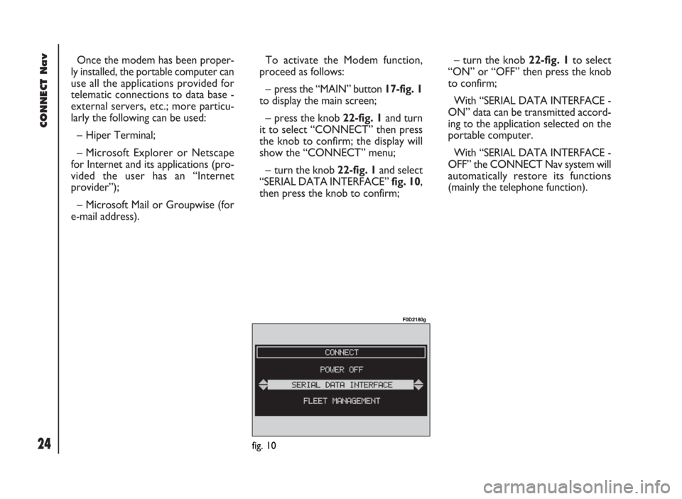
– turn the knob 22-fig. 1and select
“SERIAL DATA INTERFACE” fig. 10,
then press the knob to confirm;– turn the knob 22-fig. 1to select
“ON” or “OFF” then press the knob
to confirm;
With “SERIAL DATA INTERFACE -
ON” data can be transmitted accord-
ing to the application selected on the
portable computer.
With “SERIAL DATA INTERFACE -
OFF” the CONNECT Nav system will
automatically restore its functions
(mainly the telephone function).
fig. 10
F0D2180g
Page 26 of 246
CONNECT Nav
25
FLEET MANAGEMENT
When choosing this function, the
CONNECT Nav system sends auto-
matically SMS messages (to a suitable
preset receiver, e.g. a control centre)
containing the position of the vehicle
mounting the CONNECT Nav.
SMS messages are structured as fol-
lows:
– vehicle location (latitude and lon-
gitude)
– city (only with navigation CD in-
serted; if no CD is inserted, the field
is empty)
– street (only with navigation CD in-
serted; if no CD is inserted, the field
is empty)
– time and date
– vehicle ID (number plate).Example: LT:-2.30000;LG:-2.40000; #Benevento;#
Via Basilio Giannelli;#S:30;M:20; H:19;ND:2;D:02;MH:10;Y:2001;#BR757AM;#
To activate the FLEET MANAGE-
MENT function, proceed as follows:
– press the “MAIN” button 17-fig. 1
to display the main screen;
– turn and press the knob 22-fig. 1
to select and confirm “CONNECT”;
the display will show the “CON-
NECT” menu;
– turn and press the knob 22-fig. 1
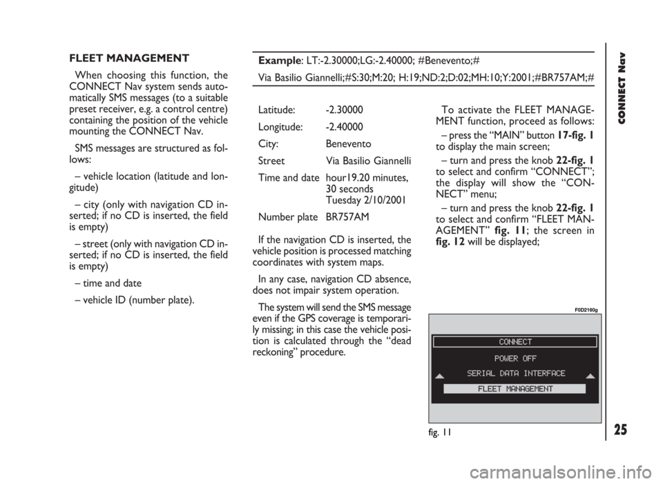
to select and confirm “FLEET MAN-
AGEMENT” fig. 11; the screen in
fig. 12will be displayed; Latitude: -2.30000
Longitude: -2.40000
City: Benevento
Street Via Basilio Giannelli
Time and date hour19.20 minutes,
30 seconds
Tuesday 2/10/2001
Number plate BR757AM
If the navigation CD is inserted, the
vehicle position is processed matching
coordinates with system maps.
In any case, navigation CD absence,
does not impair system operation.
The system will send the SMS message
even if the GPS coverage is temporari-
ly missing; in this case the vehicle posi-
tion is calculated through the “dead
reckoning” procedure.
fig. 11
F0D2160g
Page 27 of 246
CONNECT Nav
26
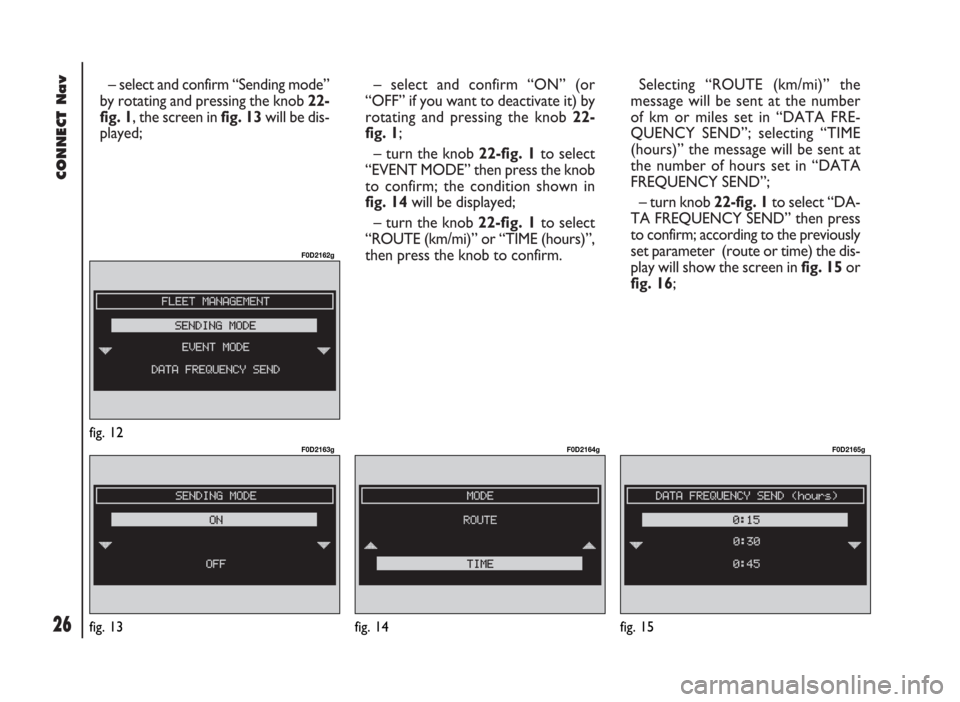
– select and confirm “Sending mode”
by rotating and pressing the knob 22-
fig. 1, the screen in fig. 13will be dis-
played;– select and confirm “ON” (or
“OFF” if you want to deactivate it) by
rotating and pressing the knob 22-
fig. 1;
– turn the knob 22-fig. 1to select
“EVENT MODE” then press the knob
to confirm; the condition shown in
fig. 14will be displayed;
– turn the knob 22-fig. 1to select
“ROUTE (km/mi)” or “TIME (hours)”,
then press the knob to confirm. Selecting “ROUTE (km/mi)” the
message will be sent at the number
of km or miles set in “DATA FRE-
QUENCY SEND”; selecting “TIME
(hours)” the message will be sent at
the number of hours set in “DATA
FREQUENCY SEND”;
– turn knob 22-fig. 1to select “DA-
TA FREQUENCY SEND” then press
to confirm; according to the previously
set parameter (route or time) the dis-
play will show the screen in fig. 15or
fig. 16;
fig. 12
F0D2162g
fig. 13
F0D2163g
fig. 14
F0D2164g
fig. 15
F0D2165g
Page 28 of 246
CONNECT Nav
27fig. 16
F0D2168g
fig. 17
F0D2166g
fig. 18
F0D2167g
– turn knob 22-fig. 1to select the
required value, then press to confirm;
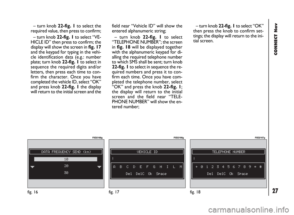
– turn knob 22-fig. 1to select “VE-
HICLE ID” then press to confirm; the
display will show the screen in fig. 17
and the keypad for typing in the vehi-
cle identification data (e.g.: number
plate; turn knob 22-fig. 1to select in
sequence the required digits and/or
letters, then press each time to con-
firm the character. Once you have
completed the vehicle ID, select “OK”
and press knob 22-fig. 1the display
will return to the initial screen and thefield near “Vehicle ID” will show the
entered alphanumeric string;
– turn knob 22-fig. 1to select
“TELEPHONE NUMBER”; the screen
in fig. 18will be displayed together
with the alphanumeric keypad for di-
alling the required telephone number
to which SMS shall be sent; turn knob
22-fig. 1to select in sequence the re-
quired numbers and press it to con-
firm each time. Once you have com-
pleted the telephone number, select
“OK” and press the knob 22-fig. 1;
the display will return to the initial
screen and the field near “TELE-
PHONE NUMBER” will show the en-
tered number;– turn knob 22-fig. 1to select “OK”
then press the knob to confirm set-
tings; the display will return to the ini-
tial screen.
Page 29 of 246
CONNECT Nav
28
Operation requirements
The “FLEET MANAGEMENT” func-
tion is operational if the following con-
ditions are present:
– “FLEET MANAGEMENT” function
active;
– service centre telephone number
entered;
– vehicle ID entered;
– frequency set (timeor route);
– CONNECT on;
– SIM card inserted;
– sufficient credit;
– GSM coverage.Failing message sending
Should one or more of the following
conditions - e.g.: CONNECT off, SIM
card not inserted or disabled, insuffi-
cient GSM coverage - take place when
sending SMS messages, their regular
transmission will be impaired.
In this case the system will store the
messages and send them later (max.
10 messages) when normal operating
conditions are restored.IMPORTANTMore particularly,
the condition of CONNECT off will
store the messages with incorrect po-
sition, since the first position present
at system switching on will be detect-
ed.
Page 30 of 246
29
CONNECT Nav
The audio system is turned on by
pressing briefly the “AUDIO” but-
ton18-fig. 1which displays the main
functions of the radio.
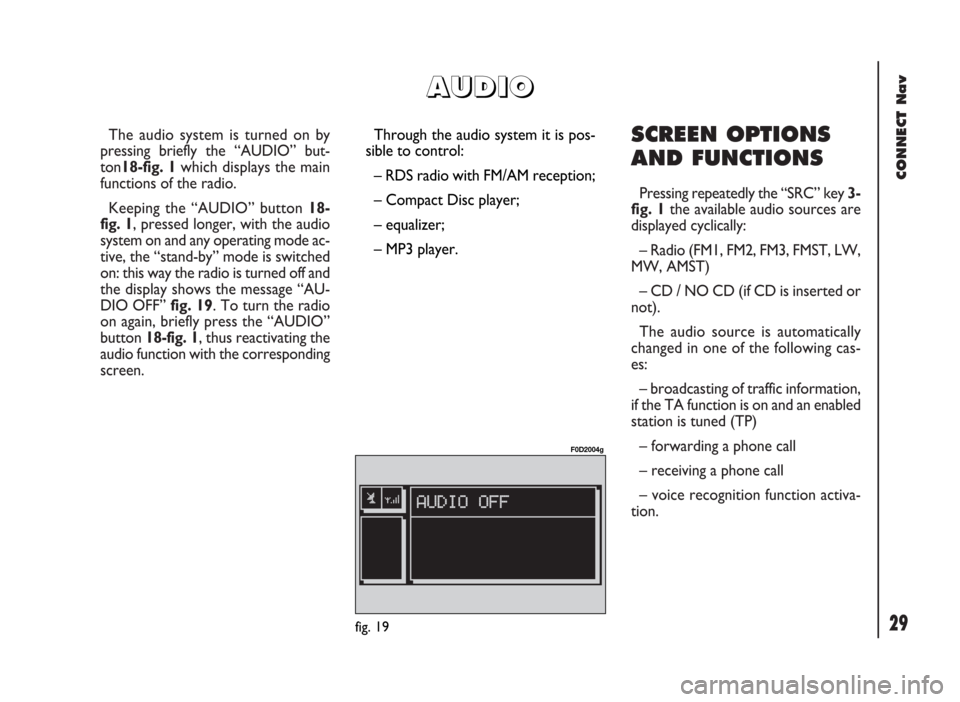
Keeping the “AUDIO” button 18-
fig. 1, pressed longer, with the audio
system on and any operating mode ac-
tive, the “stand-by” mode is switched
on: this way the radio is turned off and
the display shows the message “AU-
DIO OFF” fig. 19. To turn the radio
on again, briefly press the “AUDIO”
button 18-fig. 1, thus reactivating the
audio function with the corresponding
screen. SCREEN OPTIONS
AND FUNCTIONS
Pressing repeatedly the “SRC” key 3-
fig. 1the available audio sources are
displayed cyclically:
– Radio (FM1, FM2, FM3, FMST, LW,
MW, AMST)
– CD / NO CD (if CD is inserted or
not).
The audio source is automatically
changed in one of the following cas-
es:
– broadcasting of traffic information,
if the TA function is on and an enabled
station is tuned (TP)
– forwarding a phone call
– receiving a phone call
– voice recognition function activa-
tion.
A A
U U
D D
I I
O O
Through the audio system it is pos-
sible to control:
– RDS radio with FM/AM reception;
– Compact Disc player;
– equalizer;
– MP3 player.
fig. 19
F0D2004g