display FIAT DUCATO BASE CAMPER 2018 Owner handbook (in English)
[x] Cancel search | Manufacturer: FIAT, Model Year: 2018, Model line: DUCATO BASE CAMPER, Model: FIAT DUCATO BASE CAMPER 2018Pages: 304, PDF Size: 14.93 MB
Page 45 of 304
manualpressing the “immediate
heating” button on the timer again
(flame button 6).
The heating warning light and the
display light are switched off. The fluid
circulation pump keeps working for
approximately two minutes: the heater
can be switched back on again during
this time.
IMPORTANT The parking heater goes
off when battery voltage is low to allow
the vehicle to be started.
IMPORTANT Before turning on the
device, ensure that the fuel level is
above the reserve. Otherwise the
device could lock and require
the assistance of a Fiat Dealership.
Always turn off the heater when
refuelling and near service stations to
avoid the risk of explosion or fire
hazards.
Do not park the vehicle on
inflammable material such as paper,
grass or dry leaves: fire hazard!
The temperature near the heater
should not exceed 120°C (e.g. during
oven painting in a body shop). The
electronic control unit components may
be damaged at higher temperatures.
Whilst the heater is operating with
the engine switched off, it absorbs
energy from the battery; the engine
should therefore be left running for
a while to make sure that the battery is
properly recharged.
To check the coolant level, follow the
instructions in the "Vehicle
maintenance" chapter, "Engine coolant
system fluid" paragraph. The water in
the heating circuit must contain a
minimum percentage of 10% antifreeze.
For maintenance and repairs,
consult only a Fiat Dealership and use
only original parts.
MAINTENANCE
Have the additional heater checked
regularly at a Fiat Dealership (and
always at the start of every winter). This
will guarantee safe and economic
operation of the heater as well as a long
duration.
ADDITIONAL REAR
HEATING (Panorama and
Combinato)
(for versions/markets, where provided)
The Panorama and Combi versions
are equipped with a main heating
system plus an additional system
(available on request) with controls in
the roof panel trim above the second
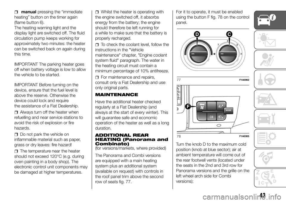
row of seats fig. 77.For it to operate, it must be enabled
using the button F fig. 78 on the control
panel.
Turn the knob D to the maximum cold
position (knob at blue sector); air at
ambient temperature will come out of
the rear footwell vents (located under
the seats in the 2nd and 3rd row for
Panorama versions and the grille on the
left wheel arch side for Combi
versions);77F1A0062
MODEF
78F1A0305
43
Page 51 of 304
The tachograph is installed and sealed
by authorised personnel: do not try
and access the device or the supply
and recording leads in any way. It is the
responsibility of the owner of the vehicle
on which the tachograph is installed to
check the device regularly.
The check must be carried out at least
every two years and a test must be
carried out to ensure that it is working
properly. Ensure that the data label
is renewed after every check and that
the label contains the specified data.SELF-LEVELLING AIR
SUSPENSION
GENERAL INFORMATION
The system only acts on the rear
wheels.
The system maintains the rear ride
setting for the vehicle constant in any
loading condition, while ensuring a
greater driving comfort.
HEIGHT ADJUSTMENT
There are 7 pre-defined levels for the
free height from the ground: from “ride
-3” to “ride 0” till “ride +3”.
The trim is shown on the multifunction
display
Automatic adjustment
When moving, the system automatically
shows that the vehicle is in 'ride setting
0' and keeps it constant.
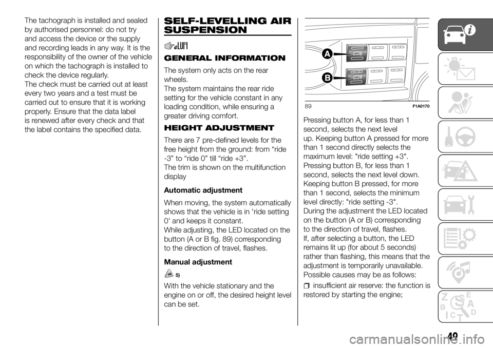
While adjusting, the LED located on the
button (A or B fig. 89) corresponding
to the direction of travel, flashes.
Manual adjustment
5)
With the vehicle stationary and the
engine on or off, the desired height level
can be set.Pressing button A, for less than 1
second, selects the next level
up. Keeping button A pressed for more
than 1 second directly selects the
maximum level: "ride setting +3".
Pressing button B, for less than 1
second, selects the next level down.
Keeping button B pressed, for more
than 1 second, selects the minimum
level directly: "ride setting -3".
During the adjustment the LED located
on the button (A or B) corresponding
to the direction of travel, flashes.
If, after selecting a button, the LED
remains lit up (for about 5 seconds)
rather than flashing, this means that the
adjustment is temporarily unavailable.
Possible causes may be as follows:insufficient air reserve: the function is
restored by starting the engine;
89F1A0170
49
Page 53 of 304
KNOWING THE INSTRUMENT PANEL
This section of the booklet gives you all
the information you need to
understand, interpret and use the
instrument panel correctly.CONTROL PANEL AND
ON-BOARD INSTRUMENTS ........... 52
DISPLAY ........................................ 56
TRIP COMPUTER ........................... 58
WARNING LIGHTS AND
MESSAGES .................................... 60
-LOW BRAKE FLUID/HANDBRAKE
ENGAGED........................................... 60
-EBD FAILURE .................................... 61
-AIR BAG FAILURE .............................. 61
-SEAT BELTS REMINDER.................... 62
-ENGINE COOLANT TEMPERATURE
TOO HIGH........................................... 63
-LOW BATTERY CHARGE ................... 63
-LOW ENGINE OIL PRESSURE ........... 64
-ENGINE OIL DETERIORATED ............ 64
-INCOMPLETE DOOR/LOAD
COMPARTMENT CLOSURE................ 65
-POWER STEERING FAILURE ............. 65
-SELF-LEVELLING SUSPENSION
FAILURE .............................................. 65
-INJECTION/EOBD SYSTEM
FAILURE .............................................. 67
-UREA INJECTION SYSTEM FAILURE. 68
-ABS FAILURE..................................... 68
-FUEL RESERVE ................................. 68
-GLOW PLUG PREHEATING / GLOW
PLUG PREHEATING FAILURE ............. 69
-LOW DIESEL EMISSIONS ADDITIVE
(UREA) LEVEL WARNING .................... 69
-VEHICLE PROTECTION SYSTEM
FAILURE - FIAT CODE ......................... 70
-REAR FOG LIGHTS............................ 70
-GENERAL FAILURE INDICATION ....... 71
-DPF (PARTICULATE FILTER)
CLEANING UNDERWAY ...................... 72
-BRAKE PAD WEAR ............................ 72
-DRIVING ADVISOR ............................ 73-TPMS SYSTEM .................................. 74
-DIPPED BEAM HEADLIGHTS ............ 75
-FOLLOW ME HOME .......................... 75
-LEFT DIRECTION INDICATOR ............ 75
-RIGHT DIRECTION INDICATOR ......... 75
-FOG LIGHTS ...................................... 75
-CRUISE CONTROL ............................ 76
-SPEED LIMITER ................................. 76
-AUTOMATIC MAIN BEAM
HEADLIGHTS ...................................... 76
-MAIN BEAM HEADLIGHTS ................ 76
-"UP" FUNCTION ................................ 77
-EXTERIOR LIGHTS FAILURE .............. 78
-LOW ENGINE OIL PRESSURE
WARNING LIGHT FAILURE ................. 78
-BRAKE LIGHT FAILURE ..................... 78
-MAIN BEAM AUTOMATISM FAULT .... 78
-POSSIBLE ICE ON ROAD .................. 79
-SPEED LIMIT EXCEEDED .................. 79
-SCHEDULED SERVICING .................. 79
-FUEL CUT-OFF DEVICE INERTIA
SWITCH TRIPPED ............................... 80
-COMFORT-MATIC SYSTEM FAILURE
INDICATION ........................................ 80
-PARKING SENSOR FAILURE ............. 80
-DRIVING ADVISOR SYSTEM
FAILURE .............................................. 80
-TRAFFIC SIGN RECOGNITION
FAILURE .............................................. 80
-LIMITED RANGE ................................ 80
-START&STOP SYSTEM
ACTIVATION/DEACTIVATION............... 81
-START&STOP FAILURE ..................... 81
-LOW DIESEL EMISSIONS ADDITIVE
(UREA) LEVEL WARNING .................... 82
-WATER IN DIESEL FILTER (Diesel
versions) .............................................. 82
51
Page 54 of 304
CONTROL PANEL AND ON-BOARD INSTRUMENTS
.
Versions with multifunction display
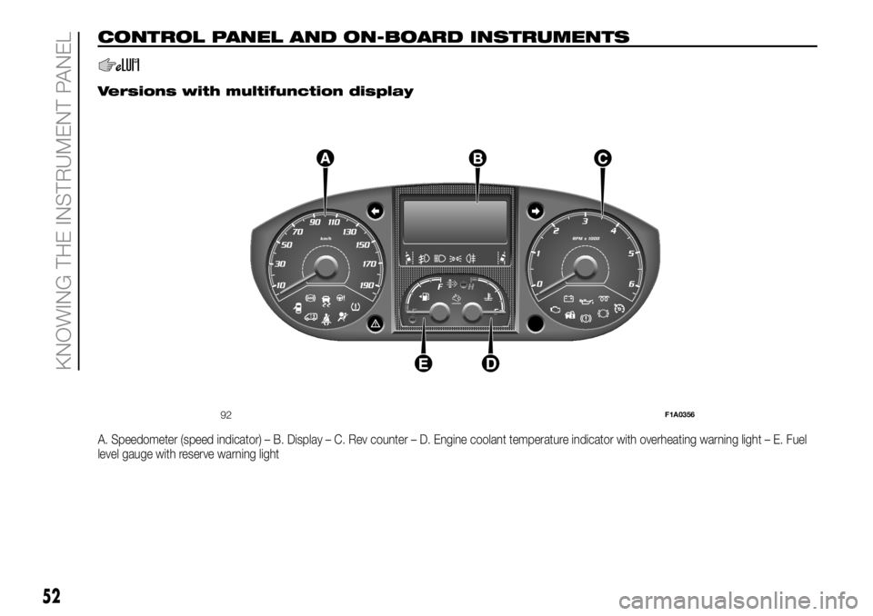
A. Speedometer (speed indicator) – B. Display – C. Rev counter – D. Engine coolant temperature indicator with overheating warning light – E. Fuel
level gauge with reserve warning light
92F1A0356
52
KNOWING THE INSTRUMENT PANEL
Page 55 of 304
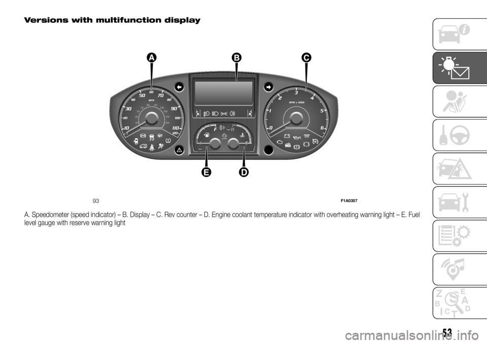
Versions with multifunction display
A. Speedometer (speed indicator) – B. Display – C. Rev counter – D. Engine coolant temperature indicator with overheating warning light – E. Fuel
level gauge with reserve warning light
93F1A0357
53
Page 56 of 304
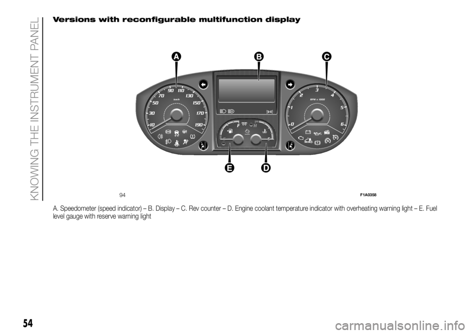
Versions with reconfigurable multifunction display
A. Speedometer (speed indicator) – B. Display – C. Rev counter – D. Engine coolant temperature indicator with overheating warning light – E. Fuel
level gauge with reserve warning light
94F1A0358
54
KNOWING THE INSTRUMENT PANEL
Page 57 of 304
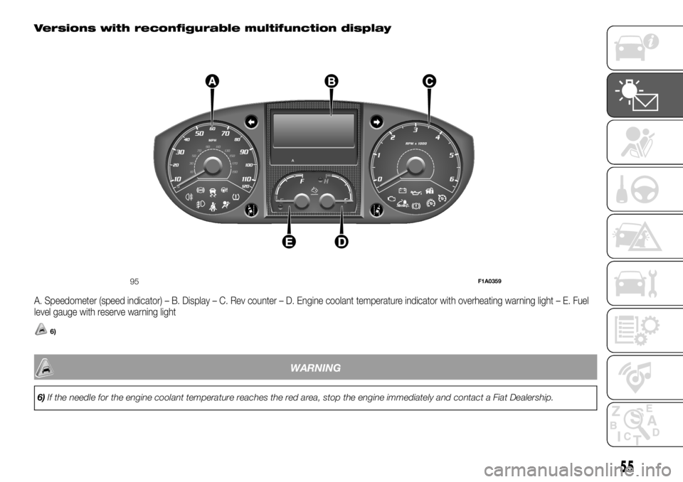
Versions with reconfigurable multifunction display
A. Speedometer (speed indicator) – B. Display – C. Rev counter – D. Engine coolant temperature indicator with overheating warning light – E. Fuel
level gauge with reserve warning light
6)
WARNING
6)If the needle for the engine coolant temperature reaches the red area, stop the engine immediately and contact a Fiat Dealership.
95F1A0359
55
Page 58 of 304
DISPLAY
(for versions/markets, where provided)
The vehicle may be equipped with a
multifunction display or with a
reconfigurable multifunction display,
able to display information that is useful
and necessary when driving.
MULTIFUNCTION
DISPLAY "STANDARD"
SCREEN
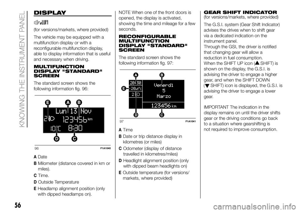
The standard screen shows the
following information fig. 96:
ADate
BMilometer (distance covered in km or
miles).
CTime.
DOutside Temperature
EHeadlamp alignment position (only
with dipped headlamps on).NOTE When one of the front doors is
opened, the display is activated,
showing the time and mileage for a few
seconds.
RECONFIGURABLE
MULTIFUNCTION
DISPLAY "STANDARD"
SCREEN
The standard screen shows the
following information fig. 97:
ATime
BDate or trip distance display in
kilometres (or miles)
COdometer (display of distance
travelled in kilometres/miles)
DHeadlight alignment position (only
with dipped beam headlights on)
EOutside temperature (for versions/
markets, where provided)GEAR SHIFT INDICATOR
(for versions/markets, where provided)
The G.S.I. system (Gear Shift Indicator)
advises the drives when to shift gear
via a dedicated indication on the
instrument panel.
Through the GSI, the driver is notified
that changing gear will allow a
reduction in fuel consumption.
When the SHIFT UP icon (
SHIFT) is
shown on the display, the G.S.I. is
advising the driver to engage a higher
gear, and when the SHIFT DOWN
(
SHIFT) icon is displayed, the G.S.I. is
advising the driver to engage a lower
gear.
IMPORTANT The indication in the
display remains on until the driver shifts
gear or the driving conditions go back
to a situation where gearshifting is
not required to improve consumption.
96F1A1040
97F1A1041
56
KNOWING THE INSTRUMENT PANEL
Page 59 of 304
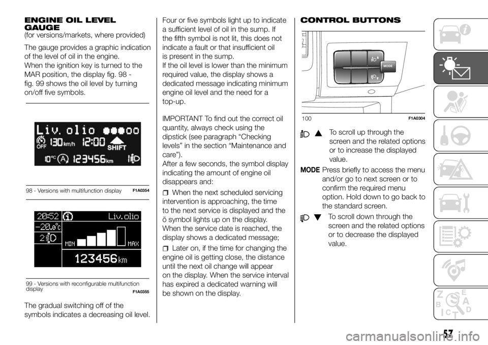
ENGINE OIL LEVEL
GAUGE
(for versions/markets, where provided)
The gauge provides a graphic indication
of the level of oil in the engine.
When the ignition key is turned to the
MAR position, the display fig. 98 -
fig. 99 shows the oil level by turning
on/off five symbols.
The gradual switching off of the
symbols indicates a decreasing oil level.Four or five symbols light up to indicate
a sufficient level of oil in the sump. If
the fifth symbol is not lit, this does not
indicate a fault or that insufficient oil
is present in the sump.
If the oil level is lower than the minimum
required value, the display shows a
dedicated message indicating minimum
engine oil level and the need for a
top-up.
IMPORTANT To find out the correct oil
quantity, always check using the
dipstick (see paragraph “Checking
levels” in the section “Maintenance and
care”).
After a few seconds, the symbol display
indicating the amount of engine oil
disappears and:
When the next scheduled servicing
intervention is approaching, the time
to the next service is displayed and the
õ symbol lights up on the display.
When the service date is reached, the
display shows a dedicated message;
Later on, if the time for changing the
engine oil is getting close, the distance
until the next oil change will appear
on the display. When the service interval
has expired a dedicated warning will
be shown on the display.CONTROL BUTTONS
To scroll up through the
screen and the related options
or to increase the displayed
value.
MODEPress briefly to access the menu
and/or go to next screen or to
confirm the required menu
option. Hold down to go back to
the standard screen.
To scroll down through the
screen and the related options
or to decrease the displayed
value.
98 - Versions with multifunction displayF1A0354
Liv.olio
MAX MIN
99 - Versions with reconfigurable multifunction
displayF1A0355
MODE
100F1A0304
57
Page 60 of 304
NOTE Theandbuttons
turn on various functions depending on
the situation, as follows:
Adjusting the vehicle interior
lighting
- with the side lights on and standard
screen active, it is possible to adjust the
brightness inside the vehicle.
Setup menu
- within the menu, they allow you to
scroll up and down;
- during setting operations they allow
an increase or decrease.
SETUP MENU
Setup menu functions
The setup menu can be activated by
pressing the MODE button briefly.
The menu comprises the following
functions:
Menu
On
Headlight alignment corrector
Speed warning
Headlight sensor
Cornering lights
Rain sensor
Trip B activation
Traffic sign
Set time
Set date
Autoclose
Units
Language
Warning volume
Service
Passenger's airbag
Daytime running lights
Automatic main beam headlights
Exit menu
Press the
orbuttons to
navigate within the menu
buttons
once to scroll through the setup menu
list.
Operating modes are different
according to the characteristics of the
option selected.
TRIP COMPUTER
IN BRIEF
The Trip computer is used to display
information on vehicleoperation
when the ignition key is turned to
MAR. This function allows you to
define two separate trips, called "Trip
A" and "Trip B", for monitoring the
"complete mission" (journey) of
the vehicle in a reciprocally
independent manner. Both functions
can be reset (reset means start of
a new journey).
"Trip A" can be used to display the
values relating to:
Outside Temperature
Range
Distance travelled A
Average consumption A
Instant consumption
Average speed A
Trip time A (driving time)
Reset Trip A
"Trip B", available on multifunction
display only, is used to display
the values relating to:
58
KNOWING THE INSTRUMENT PANEL