FIAT FIORINO 2007 Owner handbook (in English)
Manufacturer: FIAT, Model Year: 2007, Model line: FIORINO, Model: FIAT FIORINO 2007Pages: 210, PDF Size: 3.22 MB
Page 41 of 210
40
SAFETY
STARTING
AND DRIVING
WARNING
LIGHTS AND
MESSAGES
IN AN
EMERGENCY
MAINTENANCE
AND CARE
TECHNICAL
SPECIFICATIONS
INDEX
DASHBOARD
AND CONTROLS
fig. 38FF0T0027m
fig. 39F0T0042m
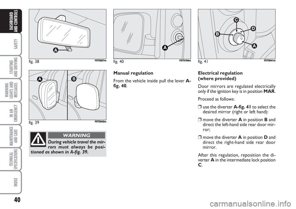
During vehicle travel the mir-
rors must always be posi-
tioned as shown in A-fig. 39.
WARNING
fig. 40F0T0194mfig. 41
B
C
D
F0T0041m
Manual regulation
From the vehicle inside pull the lever A-
fig. 40.Electrical regulation
(where provided)
Door mirrors are regulated electrically
only if the ignition key is in position MAR.
Proceed as follows:
❒use the diverter A-fig. 41to select the
desired mirror (right or left hand):
❒move the diverter Ain position Band
direct the left-hand side rear door mir-
ror;
❒move the diverter Ain position Dand
direct the right-hand side rear door
mirror.
After this regulation, reposition the di-
verter Ain the intermediate lock position
C.
Page 42 of 210
41
SAFETY
STARTING
AND DRIVING
WARNING
LIGHTS AND
MESSAGES
IN AN
EMERGENCY
MAINTENANCE
AND CARE
TECHNICAL
SPECIFICATIONS
INDEX
DASHBOARD
AND CONTROLS
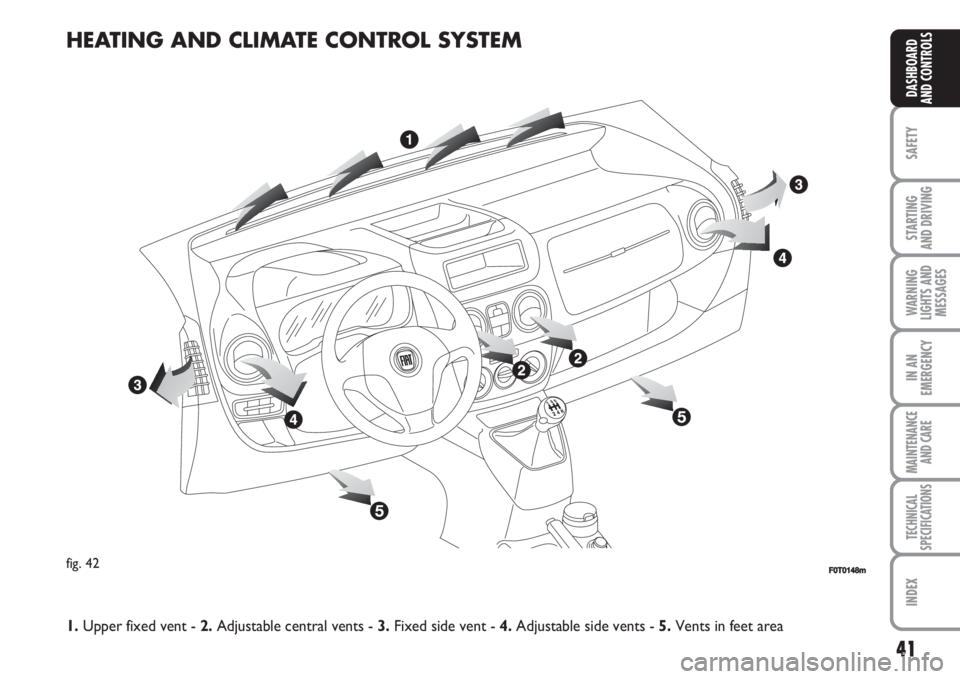
HEATING AND CLIMATE CONTROL SYSTEM
fig. 42F0T0148m
1.Upper fixed vent - 2.Adjustable central vents - 3.Fixed side vent - 4.Adjustable side vents - 5.Vents in feet area
Page 43 of 210
42
SAFETY
STARTING
AND DRIVING
WARNING
LIGHTS AND
MESSAGES
IN AN
EMERGENCY
MAINTENANCE
AND CARE
TECHNICAL
SPECIFICATIONS
INDEX
DASHBOARD
AND CONTROLS
fig. 44FF0T0030mfig. 43F0T0031m
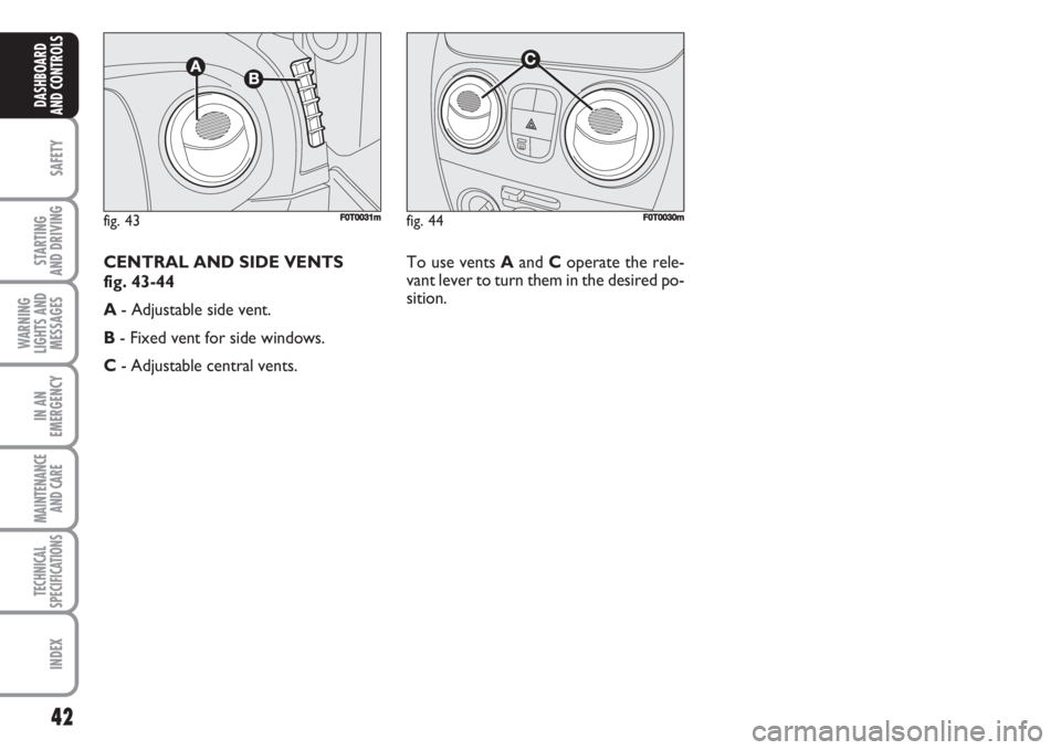
To use vents Aand Coperate the rele-
vant lever to turn them in the desired po-
sition. CENTRAL AND SIDE VENTS
fig. 43-44
A- Adjustable side vent.
B- Fixed vent for side windows.
C- Adjustable central vents.
Page 44 of 210
43
SAFETY
STARTING
AND DRIVING
WARNING
LIGHTS AND
MESSAGES
IN AN
EMERGENCY
MAINTENANCE
AND CARE
TECHNICAL
SPECIFICATIONS
INDEX
DASHBOARD
AND CONTROLS
HEATING AND VENTILATION
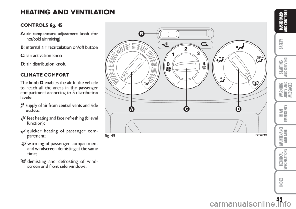
CONTROLS fig. 45
A: air temperature adjustment knob (for
hot/cold air mixing)
B: internal air recirculation on/off button
C: fan activation knob
D: air distribution knob.
CLIMATE COMFORT
The knob Denables the air in the vehicle
to reach all the areas in the passenger
compartment according to 5 distribution
levels:
¶supply of air from central vents and side
outlets;
ßfeet heating and face refreshing (bilevel
function);
©quicker heating of passenger com-
partment;
®warming of passenger compartment
and windscreen demisting at the same
time;
-demisting and defrosting of wind-
screen and front side windows.
fig. 45FF0T0074m
Page 45 of 210
44
SAFETY
STARTING
AND DRIVING
WARNING
LIGHTS AND
MESSAGES
IN AN
EMERGENCY
MAINTENANCE
AND CARE
TECHNICAL
SPECIFICATIONS
INDEX
DASHBOARD
AND CONTROLS
HEATING
Proceed as follows:
❒turn knob Aall the way to the right
(line on -);
❒turn knob Cto the required speed;
❒turn knob Don:
®to warm the feet and demist the
windscreen at the same time;
ßto deliver air to the feet area and re-
lease cooler air from central vents
and outlets on the dashboard;
©to heat the area quickly.
FAST HEATING
Proceed as follows:
❒close all the vents on the dashboard;
❒turn knob Aon
-;
❒turn knob Con 4
-;
❒turn knob Don
©;FAST DEMISTING/
DEFROSTING OF WINDSCREEN
AND FRONT SIDE WINDOWS
(MAX-DEF function)
Proceed as follows:
❒turn knob Aon
-;
❒turn knob Con 4
-;
❒turn knob Don
-;
❒turn cursor Bon
¶.
After demisting/defrosting, operate the
standard controls to restore the required
comfort conditions.Window demisting
In the event of considerable external mois-
ture and/or rain and/or considerable dif-
ferences in temperature inside and out-
side the passenger compartment, perform
the following preventive demisting proce-
dure:
❒turn cursor Bon
Y;
❒turn knob Aon
-;
❒turn knob Con 2;
❒turn knob Don
-having the possi-
bility to reach position
®if the win-
dows are not misty.
Page 46 of 210
45
SAFETY
STARTING
AND DRIVING
WARNING
LIGHTS AND
MESSAGES
IN AN
EMERGENCY
MAINTENANCE
AND CARE
TECHNICAL
SPECIFICATIONS
INDEX
DASHBOARD
AND CONTROLS
REGULATING THE
FAN SPEED
To ventilate the passenger compartment
properly proceed as follows:
❒fully open the central air vents and side
outlets;
❒turn knob Ato the blue section;
❒turn cursor Bon
¶;
❒turn knob Cto the required speed;
❒turn knob Don
¥.ACTIVATION OF INTERNAL
AIR RECIRCULATION
Turn cursor Bto position
v.
It is advisable to activate air recirculation
during vehicle stops in queues or tunnels
to prevent the introduction of polluted air
from the outside.
Do not use the function for a long time,
particularly if there are many passengers
on board, to prevent the windows from
misting up.
IMPORTANT The internal air recircula-
tion system makes it possible to reach the
required “heating” or “cooling” condi-
tions faster. Do not use the air recircula-
tion function on rainy/cold days as it would
considerably increase the possibility of the
windows misting inside. DEMISTING/DEFROSTING OF REAR
HEATED WINDOW AND DOOR
MIRRORS (where provided)
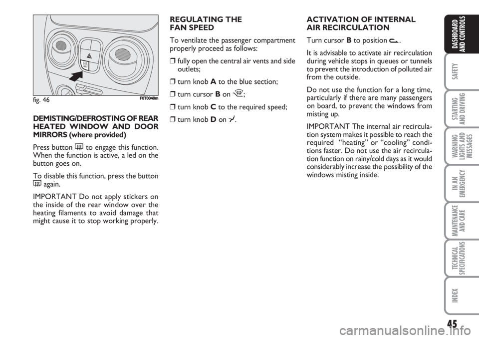
Press button (to engage this function.
When the function is active, a led on the
button goes on.
To disable this function, press the button
(again.
IMPORTANT Do not apply stickers on
the inside of the rear window over the
heating filaments to avoid damage that
might cause it to stop working properly.
fig. 46F0T0048m
Page 47 of 210
46
SAFETY
STARTING
AND DRIVING
WARNING
LIGHTS AND
MESSAGES
IN AN
EMERGENCY
MAINTENANCE
AND CARE
TECHNICAL
SPECIFICATIONS
INDEX
DASHBOARD
AND CONTROLS
MANUAL CLIMATE CONTROL SYSTEM (where provided)
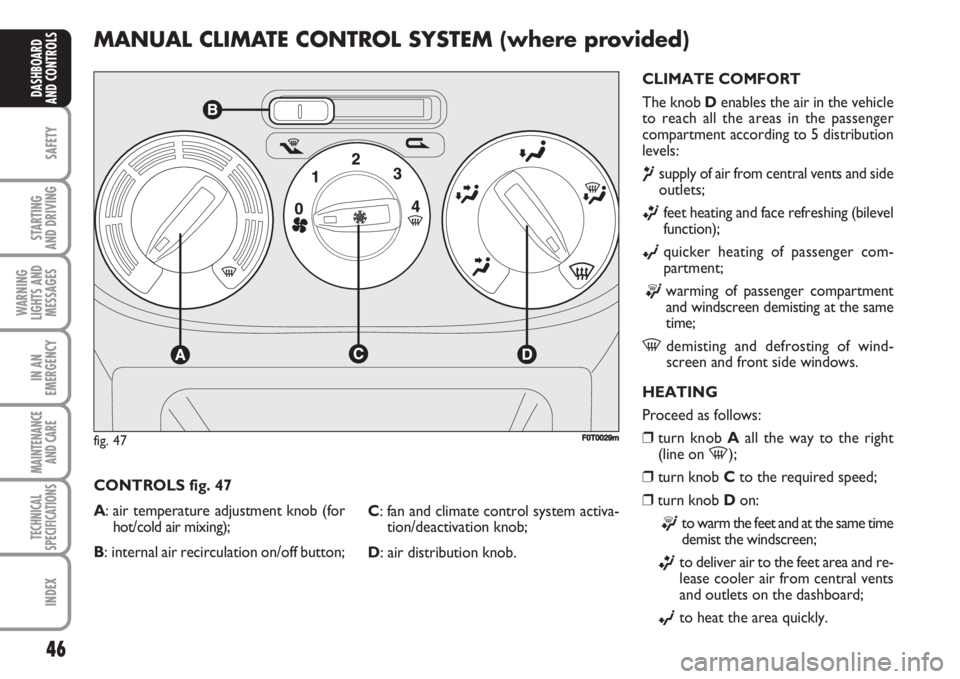
CLIMATE COMFORT
The knob Denables the air in the vehicle
to reach all the areas in the passenger
compartment according to 5 distribution
levels:
¶supply of air from central vents and side
outlets;
ßfeet heating and face refreshing (bilevel
function);
©quicker heating of passenger com-
partment;
®warming of passenger compartment
and windscreen demisting at the same
time;
-demisting and defrosting of wind-
screen and front side windows.
HEATING
Proceed as follows:
❒turn knob Aall the way to the right
(line on
-);
❒turn knob Cto the required speed;
❒turn knob Don:
®to warm the feet and at the same time
demist the windscreen;
ßto deliver air to the feet area and re-
lease cooler air from central vents
and outlets on the dashboard;
©to heat the area quickly. CONTROLS fig. 47
A: air temperature adjustment knob (for
hot/cold air mixing);
B: internal air recirculation on/off button;C: fan and climate control system activa-
tion/deactivation knob;
D: air distribution knob.
fig. 47FF0T0029m
Page 48 of 210
47
SAFETY
STARTING
AND DRIVING
WARNING
LIGHTS AND
MESSAGES
IN AN
EMERGENCY
MAINTENANCE
AND CARE
TECHNICAL
SPECIFICATIONS
INDEX
DASHBOARD
AND CONTROLS
FAST HEATING
Proceed as follows:
❒close all the vents on the dashboard;
❒turn knob Aon
-;
❒turn knob Con 4
-;
❒turn knob Don
ß.
FAST DEMISTING/
DEFROSTING OF WINDSCREEN
AND FRONT SIDE WINDOWS
(MAX-DEF function)
Proceed as follows:
❒turn knob Aon
-;
❒turn knob Con 4
-;
❒turn knob Don
-;
❒turn cursor Bon
¶.
After demisting/defrosting, operate the
standard controls to restore the required
comfort conditions.
IMPORTANT The climate control system
is very useful for faster demisting because
it dries the air. Regulate the controls as
described above and engage the climate
control by pressing knob C.Window demisting
In the event of considerable external mois-
ture and/or rain and/or considerable dif-
ferences in temperature inside and out-
side the passenger compartment, perform
the following preventive demisting proce-
dure:
❒turn cursor Bon
¶;
❒turn knob Aon
-;
❒turn knob Con 2;
❒turn knob Don
-having the possi-
bility to reach position
®if the win-
dows are not misty. DEMISTING/DEFROSTING
OF REAR HEATED WINDOW
AND DOOR MIRRORS
(where provided)
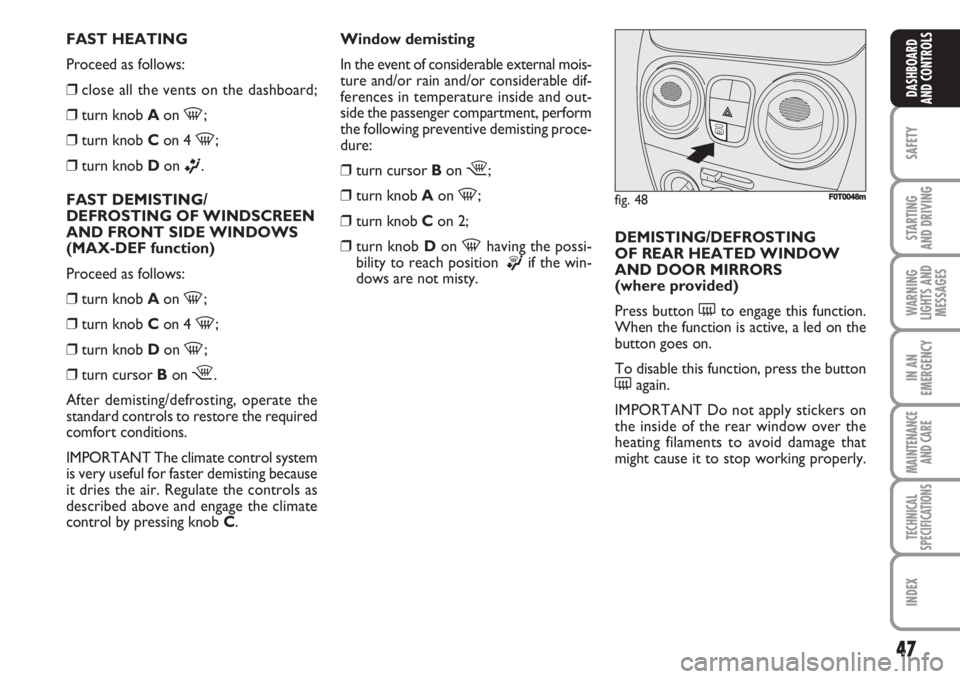
Press button (to engage this function.
When the function is active, a led on the
button goes on.
To disable this function, press the button
(again.
IMPORTANT Do not apply stickers on
the inside of the rear window over the
heating filaments to avoid damage that
might cause it to stop working properly.
fig. 48F0T0048m
Page 49 of 210
48
SAFETY
STARTING
AND DRIVING
WARNING
LIGHTS AND
MESSAGES
IN AN
EMERGENCY
MAINTENANCE
AND CARE
TECHNICAL
SPECIFICATIONS
INDEX
DASHBOARD
AND CONTROLS
CLIMATE CONTROL (cooling)
Proceed as follows:
❒turn knob Ato the blue section;
❒turn knob Con 4
-;
❒turn cursor Bon
v;
❒turn knob Don
©;
❒turn knob C.
Regulating cooling
Proceed as follows:
❒turn cursor Bon
¶;
❒turn knob Ato the right to increase the
temperature;
❒turn knob Cto the left to reduce the
fan speed.
SERVICING THE SYSTEM
Let the climate control system run for at
least 10 minutes every month during the
winter. Have the system inspected at a Fi-
at Dealership before the summer. REGULATING THE FAN SPEED
To ventilate the passenger compartment
properly proceed as follows:
❒fully open the central air vents and side
outlets;
❒turn knob Ato the blue section;
❒turn cursor Bon
¶;
❒turn knob Cto the required speed;
❒turn knob Don
©.ACTIVATION OF
INTERNAL AIR
RECIRCULATION
Turn cursor Bto position
v.
It is advisable to activate air recirculation
during vehicle stops in queues or tunnels
to prevent the introduction of polluted air
from the outside.
Do not use the function for a long time,
particularly if there are many passengers
on board, to prevent the windows from
misting up.
IMPORTANT The internal air recircula-
tion system makes it possible to reach the
required “heating” or “cooling” condi-
tions faster. Do not use the air recircula-
tion function on rainy/cold days as it would
considerably increase the possibility of the
windows misting inside.
Page 50 of 210
49
SAFETY
STARTING
AND DRIVING
WARNING
LIGHTS AND
MESSAGES
IN AN
EMERGENCY
MAINTENANCE
AND CARE
TECHNICAL
SPECIFICATIONS
INDEX
DASHBOARD
AND CONTROLS
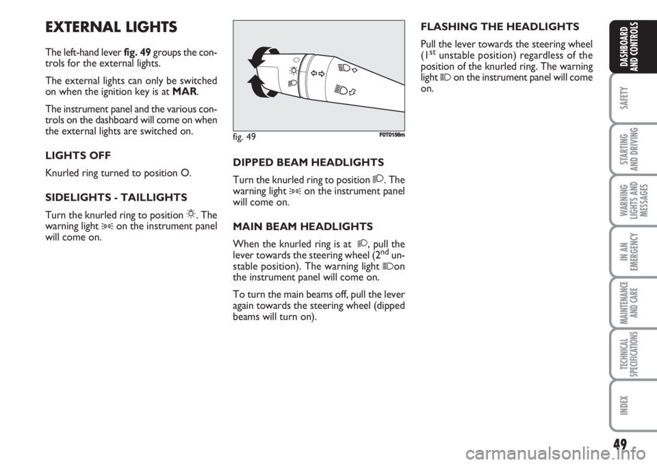
EXTERNAL LIGHTS
The left-hand lever fig. 49groups the con-
trols for the external lights.
The external lights can only be switched
on when the ignition key is at MAR.
The instrument panel and the various con-
trols on the dashboard will come on when
the external lights are switched on.
LIGHTS OFF
Knurled ring turned to position O.
SIDELIGHTS - TAILLIGHTS
Turn the knurled ring to position 6. The
warning light
3on the instrument panel
will come on.FLASHING THE HEADLIGHTS
Pull the lever towards the steering wheel
(1
stunstable position) regardless of the
position of the knurled ring. The warning
light
1on the instrument panel will come
on.
DIPPED BEAM HEADLIGHTS
Turn the knurled ring to position 2. The
warning light
3on the instrument panel
will come on.
MAIN BEAM HEADLIGHTS
When the knurled ring is at
2, pull the
lever towards the steering wheel (2ndun-
stable position). The warning light 1on
the instrument panel will come on.
To turn the main beams off, pull the lever
again towards the steering wheel (dipped
beams will turn on).
fig. 49F0T0156m