engine FIAT FIORINO 2017 Owner handbook (in English)
[x] Cancel search | Manufacturer: FIAT, Model Year: 2017, Model line: FIORINO, Model: FIAT FIORINO 2017Pages: 272, PDF Size: 5.87 MB
Page 19 of 272
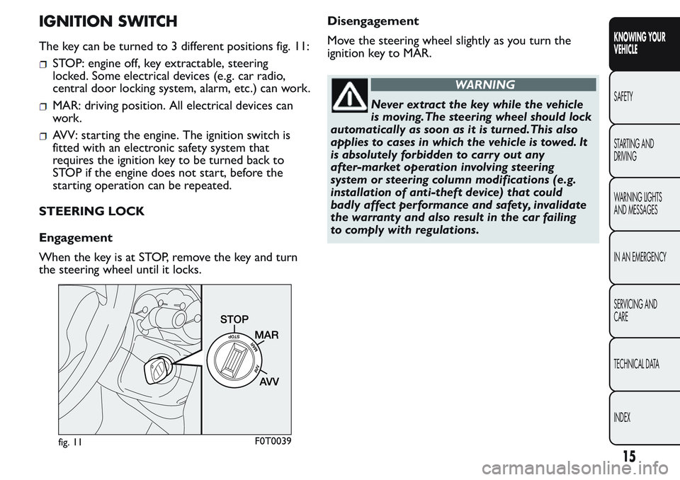
IGNITION SWITCH
The key can be turned to 3 different positions fig. 11:
STOP: engine off, key extractable, steering
locked. Some electrical devices (e.g. car radio,
central door locking system, alarm, etc.) can work.
MAR: driving position. All electrical devices can
work.
AVV: starting the engine. The ignition switch is
fitted with an electronic safety system that
requires the ignition key to be turned back to
STOP if the engine does not start, before the
starting operation can be repeated.
STEERING LOCK
Engagement
When the key is at STOP, remove the key and turn
the steering wheel until it locks.Disengagement
Move the steering wheel slightly as you turn the
ignition key to MAR.
WARNING
Never extract the key while the vehicle
is moving.The steering wheel should lock
automatically as soon as it is turned.This also
applies to cases in which the vehicle is towed. It
is absolutely forbidden to carr y out any
after-market operation involving steering
system or steering column modifications (e.g.
installation of anti-theft device) that could
badly affect performance and safety, invalidate
the warranty and also result in the car failing
to comply with regulations.
fig. 11F0T0039
15
KNOWING YOUR
VEHICLE
SAFETY
STARTING AND
DRIVING
WARNING LIGHTS
AND MESSAGES
IN AN EMERGENCY
SERVICING AND
CARE
TECHNICAL DATA
INDEX
Page 20 of 272
ON-BOARD INSTRUMENTS
The instrument background colour and type may
vary according to the versions.
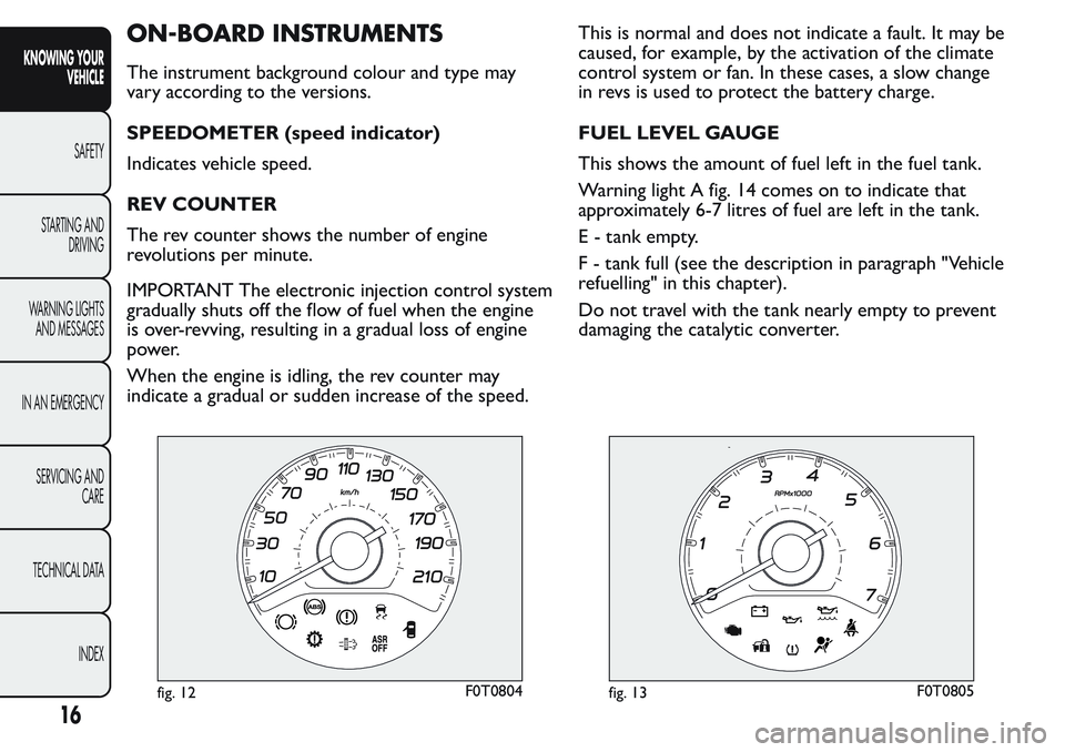
SPEEDOMETER (speed indicator)
Indicates vehicle speed.
REV COUNTER
The rev counter shows the number of engine
revolutions per minute.
IMPORTANT The electronic injection control system
gradually shuts off the flow of fuel when the engine
is over-revving, resulting in a gradual loss of engine
power.
When the engine is idling, the rev counter may
indicate a gradual or sudden increase of the speed.This is normal and does not indicate a fault. It may be
caused, for example, by the activation of the climate
control system or fan. In these cases, a slow change
in revs is used to protect the battery charge.
FUEL LEVEL GAUGE
This shows the amount of fuel left in the fuel tank.
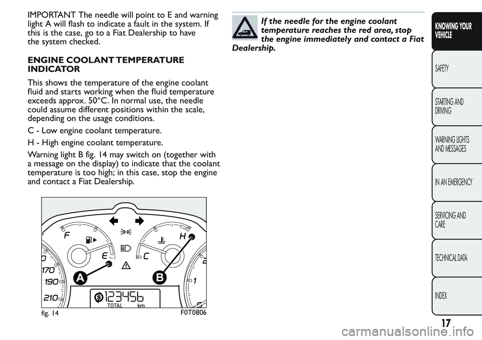
Warning light A fig. 14 comes on to indicate that
approximately 6-7 litres of fuel are left in the tank.
E - tank empty.
F - tank full (see the description in paragraph "Vehicle
refuelling" in this chapter).
Do not travel with the tank nearly empty to prevent
damaging the catalytic converter.
fig. 12F0T0804fig. 13F0T0805
16
KNOWING YOUR
VEHICLE
SAFETY
STARTING AND
DRIVING
WARNING LIGHTS
AND MESSAGES
IN AN EMERGENCY
SERVICING AND
CARE
TECHNICAL DATA
INDEX
Page 21 of 272
IMPORTANT The needle will point to E and warning
light A will flash to indicate a fault in the system. If
this is the case, go to a Fiat Dealership to have
the system checked.
ENGINE COOLANT TEMPERATURE
INDICATOR
This shows the temperature of the engine coolant
fluid and starts working when the fluid temperature
exceeds approx. 50°C. In normal use, the needle
could assume different positions within the scale,
depending on the usage conditions.
C - Low engine coolant temperature.
H - High engine coolant temperature.
Warning light B fig. 14 may switch on (together with
a message on the display) to indicate that the coolant
temperature is too high; in this case, stop the engine
and contact a Fiat Dealership.If the needle for the engine coolant
temperature reaches the red area, stop
the engine immediately and contact a Fiat
Dealership.
fig. 14F0T0806
17
KNOWING YOUR
VEHICLE
SAFETY
STARTING AND
DRIVING
WARNING LIGHTS
AND MESSAGES
IN AN EMERGENCY
SERVICING AND
CARE
TECHNICAL DATA
INDEX
Page 38 of 272
“Trip B” may be disabled (see “Activating
Trip B”). “Range” and “Instant
consumption" parameters cannot be
reset .
Values displayed
Range (for versions/markets where provided)
This value shows the distance that the car can still
cover before needing fuel, assuming that driving style
is unvaried. “----”will appear on the display in
the following cases:
range is lower than 50 km (or 30 mi)
vehicle is left parked with the engine running for a
long time.
IMPORTANT The range can be affected by several
factors: driving style (see “Driving style” in the
“Starting and driving” section), type of route
(motorway, towns and cities, mountain roads, etc.),
conditions of use (load, tyre pressures, etc.). Trip
planning must therefore take the above into account.
Distance travelled
This value shows the distance covered from the start
of the new journey.
Average consumption
This value shows the approximate average fuel
consumption from the start of the new journey.Current consumption
This value shows the fuel consumption. The value is
constantly updated. The message “----” will appear
on the display if the vehicle is parked with the engine
running.
Average speed
Shows the average speed of the vehicle by using the
overall time elapsed since the start of a new journey.
Journey time
Time elapsed since the start of the new journey.
IMPORTANT If there is no information, the Trip
computer displays "----" in place of the value. When
normal operating conditions are restored, the
counting of the various values is resumed, without
either zeroing the values displayed prior to the
problem, or starting a new journey.
Control TRIP button
The TRIP button is located at the end of the right
stalk fig. 22. With the ignition key turned to
MAR-ON, this button allows you to view the
previously described values and also zero them to
begin a new journey:
press briefly to display the different values;
long push to reset and then start a new journey.
This begins after a reset:
34
KNOWING YOUR
VEHICLE
SAFETY
STARTING AND
DRIVING
WARNING LIGHTS
AND MESSAGES
IN AN EMERGENCY
SERVICING AND
CARE
TECHNICAL DATA
INDEX
Page 45 of 272
HEADREST
FRONT
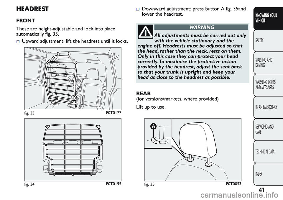
These are height-adjustable and lock into place
automatically fig. 35.
Upward adjustment: lift the headrest until it locks.
Downward adjustment: press button A fig. 35and
lower the headrest.
WARNING
All adjustments must be carried out only
with the vehicle stationary and the
engine off. Headrests must be adjusted so that
the head, rather than the neck, rests on them.
Only in this case they can protect your head
correctly.To maximise the protective action
provided by the headrest , adjust the seat back
so that your trunk is upright and keep your
head as close to the headrest as possible.
REAR
(for versions/markets, where provided)
Lift up to use.
fig. 33F0T0177
fig. 34F0T0195fig. 35F0T0053
41
KNOWING YOUR
VEHICLE
SAFETY
STARTING AND
DRIVING
WARNING LIGHTS
AND MESSAGES
IN AN EMERGENCY
SERVICING AND
CARE
TECHNICAL DATA
INDEX
Page 47 of 272
STEERING WHEEL
The height and axial position of the steering wheel
can be adjusted on some versions.
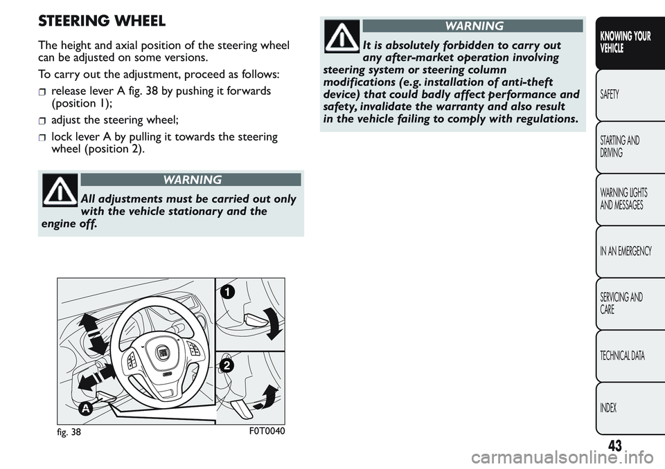
To carry out the adjustment, proceed as follows:
release lever A fig. 38 by pushing it forwards
(position 1);
adjust the steering wheel;
lock lever A by pulling it towards the steering
wheel (position 2).
WARNING
All adjustments must be carried out only
with the vehicle stationary and the
engine off.
WARNING
It is absolutely forbidden to carr y out
any after-market operation involving
steering system or steering column
modifications (e.g. installation of anti-theft
device) that could badly affect performance and
safety, invalidate the warranty and also result
in the vehicle failing to comply with regulations.
fig. 38F0T0040
43
KNOWING YOUR
VEHICLE
SAFETY
STARTING AND
DRIVING
WARNING LIGHTS
AND MESSAGES
IN AN EMERGENCY
SERVICING AND
CARE
TECHNICAL DATA
INDEX
Page 53 of 272
knob A turned to blue section
take the slider B to
turn knob C to the required speed
turn knob D to
INTERNAL AIR RECIRCULATION
ACTIVATION
Take the slider B to
.
It is advisable to switch the internal air recirculation
on while standing in queues or in tunnels to prevent
the introduction of polluted air.
Do not use the function for a long time, particularly
if there are several passengers on board, to prevent
the windows from steaming up.
IMPORTANT The internal air recirculation system
makes it possible to reach the required heating
or cooling conditions more quickly. Do not use the
internal air recirculation function on rainy/cold
days to avoid the possibility of the windows misting.
DEMISTING/DEFROSTING OF HEATED
REAR WINDSCREEN AND DOOR MIRRORS
(for versions/markets, where provided)
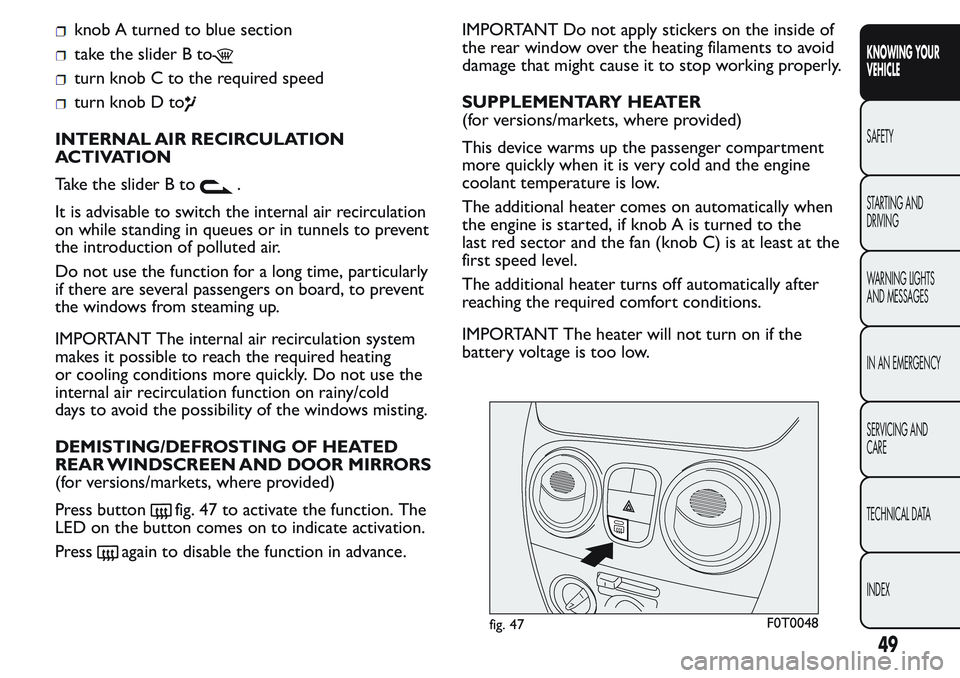
Press button
fig. 47 to activate the function. The
LED on the button comes on to indicate activation.
Press
again to disable the function in advance.IMPORTANT Do not apply stickers on the inside of
the rear window over the heating filaments to avoid
damage that might cause it to stop working properly.
SUPPLEMENTARY HEATER
(for versions/markets, where provided)
This device warms up the passenger compartment
more quickly when it is very cold and the engine
coolant temperature is low.
The additional heater comes on automatically when
the engine is started, if knob A is turned to the
last red sector and the fan (knob C) is at least at the
first speed level.
The additional heater turns off automatically after
reaching the required comfort conditions.
IMPORTANT The heater will not turn on if the
battery voltage is too low.
fig. 47F0T0048
49
KNOWING YOUR
VEHICLE
SAFETY
STARTING AND
DRIVING
WARNING LIGHTS
AND MESSAGES
IN AN EMERGENCY
SERVICING AND
CARE
TECHNICAL DATA
INDEX
Page 56 of 272
turn knob C to
take the slider B to
turn knob D to
press knob C.
Adjusting cooling
Proceed as follows:
take the slider B to
turn knob A rightwards to increase the
temperature
turn knob C leftwards to reduce the fan speed.
DEMISTING/DEFROSTING OF HEATED
REAR WINDSCREEN AND DOOR MIRRORS
(for versions/markets, where provided)
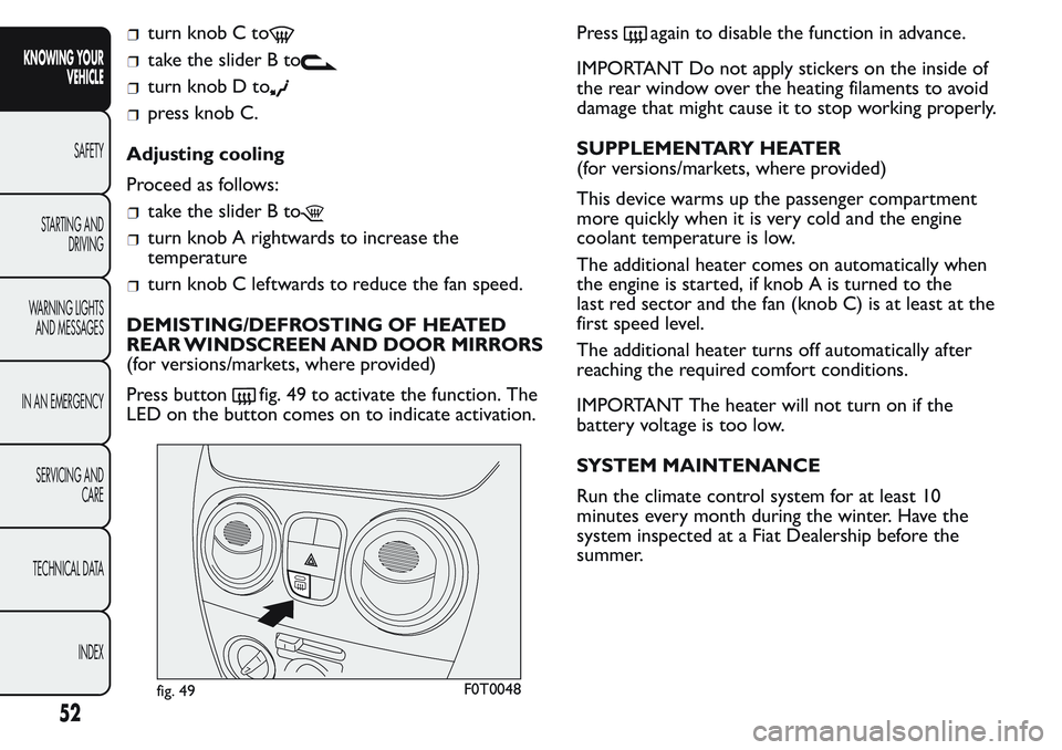
Press button
fig. 49 to activate the function. The
LED on the button comes on to indicate activation.Press
again to disable the function in advance.
IMPORTANT Do not apply stickers on the inside of
the rear window over the heating filaments to avoid
damage that might cause it to stop working properly.
SUPPLEMENTARY HEATER
(for versions/markets, where provided)
This device warms up the passenger compartment
more quickly when it is very cold and the engine
coolant temperature is low.
The additional heater comes on automatically when
the engine is started, if knob A is turned to the
last red sector and the fan (knob C) is at least at the
first speed level.
The additional heater turns off automatically after
reaching the required comfort conditions.
IMPORTANT The heater will not turn on if the
battery voltage is too low.
SYSTEM MAINTENANCE
Run the climate control system for at least 10
minutes every month during the winter. Have the
system inspected at a Fiat Dealership before the
summer.
fig. 49F0T0048
52
KNOWING YOUR
VEHICLE
SAFETY
STARTING AND
DRIVING
WARNING LIGHTS
AND MESSAGES
IN AN EMERGENCY
SERVICING AND
CARE
TECHNICAL DATA
INDEX
Page 58 of 272
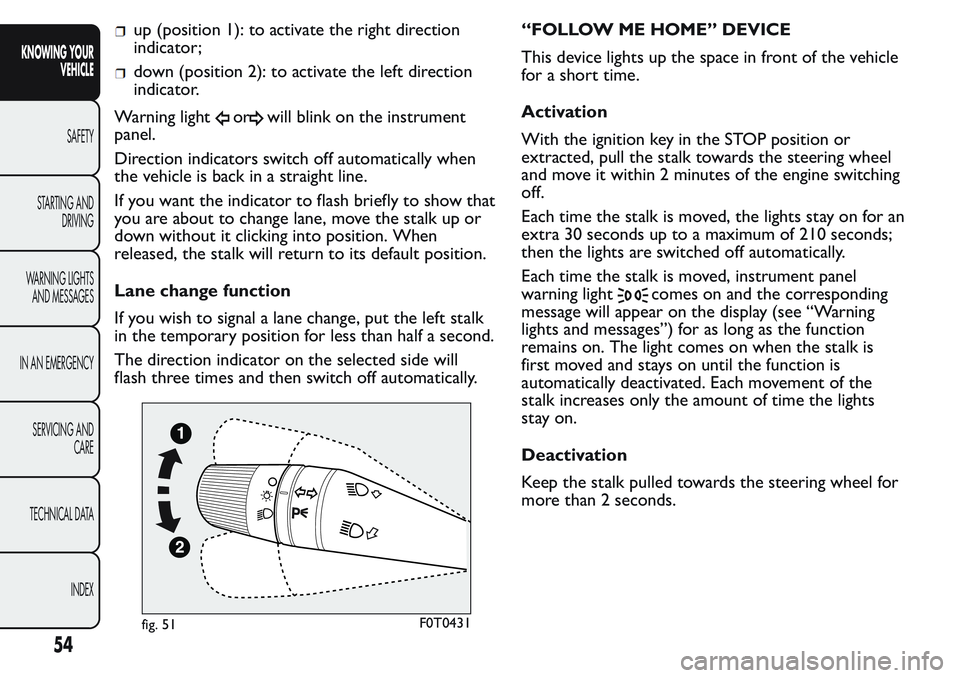
up (position 1): to activate the right direction
indicator;
down (position 2): to activate the left direction
indicator.
Warning light
orwill blink on the instrument
panel.
Direction indicators switch off automatically when
the vehicle is back in a straight line.
If you want the indicator to flash briefly to show that
you are about to change lane, move the stalk up or
down without it clicking into position. When
released, the stalk will return to its default position.
Lane change function
If you wish to signal a lane change, put the left stalk
in the temporary position for less than half a second.
The direction indicator on the selected side will
flash three times and then switch off automatically.“FOLLOW ME HOME” DEVICE
This device lights up the space in front of the vehicle
for a short time.
Activation
With the ignition key in the STOP position or
extracted, pull the stalk towards the steering wheel
and move it within 2 minutes of the engine switching
off.
Each time the stalk is moved, the lights stay on for an
extra 30 seconds up to a maximum of 210 seconds;
then the lights are switched off automatically.
Each time the stalk is moved, instrument panel
warning light
comes on and the corresponding
message will appear on the display (see “Warning
lights and messages”) for as long as the function
remains on. The light comes on when the stalk is
first moved and stays on until the function is
automatically deactivated. Each movement of the
stalk increases only the amount of time the lights
stay on.
Deactivation
Keep the stalk pulled towards the steering wheel for
more than 2 seconds.
fig. 51F0T0431
54
KNOWING YOUR
VEHICLE
SAFETY
STARTING AND
DRIVING
WARNING LIGHTS
AND MESSAGES
IN AN EMERGENCY
SERVICING AND
CARE
TECHNICAL DATA
INDEX
Page 61 of 272
If necessary (when overtaking for instance)
acceleration is possible by simply pressing the
accelerator pedal: releasing the accelerator pedal, the
car will return to the speed memorised previously.
Restoring the stored speed
If the device has been switched off, for example by
pressing the brake or clutch pedal, the memorised
speed can be restored as follows:
accelerate gently until a speed close to that stored
one is reached;
engage the gear selected when storing the speed;
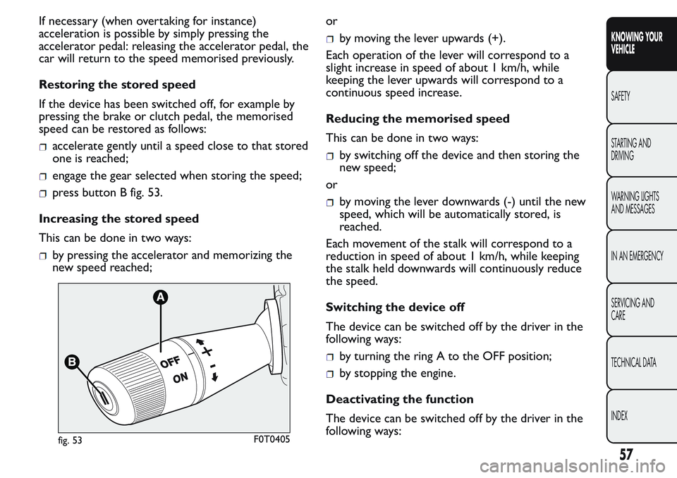
press button B fig. 53.
Increasing the stored speed
This can be done in two ways:
by pressing the accelerator and memorizing the
new speed reached;or
by moving the lever upwards (+).
Each operation of the lever will correspond to a
slight increase in speed of about 1 km/h, while
keeping the lever upwards will correspond to a
continuous speed increase.
Reducing the memorised speed
This can be done in two ways:
by switching off the device and then storing the
new speed;
or
by moving the lever downwards (-) until the new
speed, which will be automatically stored, is
reached.
Each movement of the stalk will correspond to a
reduction in speed of about 1 km/h, while keeping
the stalk held downwards will continuously reduce
the speed.
Switching the device off
The device can be switched off by the driver in the
following ways:
by turning the ring A to the OFF position;
by stopping the engine.
Deactivating the function
The device can be switched off by the driver in the
following ways:
fig. 53F0T0405
57
KNOWING YOUR
VEHICLE
SAFETY
STARTING AND
DRIVING
WARNING LIGHTS
AND MESSAGES
IN AN EMERGENCY
SERVICING AND
CARE
TECHNICAL DATA
INDEX