climate control FIAT FIORINO 2017 Owner handbook (in English)
[x] Cancel search | Manufacturer: FIAT, Model Year: 2017, Model line: FIORINO, Model: FIAT FIORINO 2017Pages: 272, PDF Size: 5.87 MB
Page 7 of 272
KNOWING YOUR VEHICLE
DASHBOARD
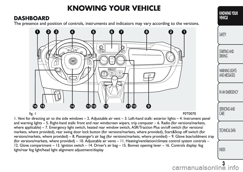
The presence and position of controls, instruments and indicators may vary according to the versions.
1. Vent for directing air to the side windows – 2. Adjustable air vent – 3. Left-hand stalk: exterior lights – 4. Instrument panel
and warning lights – 5. Right-hand stalk: front and rear windscreen wipers, trip computer – 6. Radio (for versions/markets,
where applicable) – 7. Emergency light switch, heated rear window switch, ASR/Traction Plus on/off switch (for versions/
markets, where provided), rear swing door lock button (for versions/markets, where provided), Start&Stop off switch (for
versions/markets, where provided) – 8. Passenger's air bag (for versions/markets, where provided) – 9. Glove box/oddment tray
(for versions/markets, where provided) – 10. Adjustable air vents – 11. Heating/ventilation/climate control system controls –
12. Glove compartment – 13. Ignition switch – 14. Driver's air bag – 15. Bonnet opening lever – 16. Controls display: fog
light/rear fog light/head light alignment adjustment/display
fig. 1F0T0070
3
KNOWING YOUR
VEHICLE
SAFETY
STARTING AND
DRIVING
WARNING LIGHTS
AND MESSAGES
IN AN EMERGENCY
SERVICING AND
CARE
TECHNICAL DATA
INDEX
Page 20 of 272
ON-BOARD INSTRUMENTS
The instrument background colour and type may
vary according to the versions.
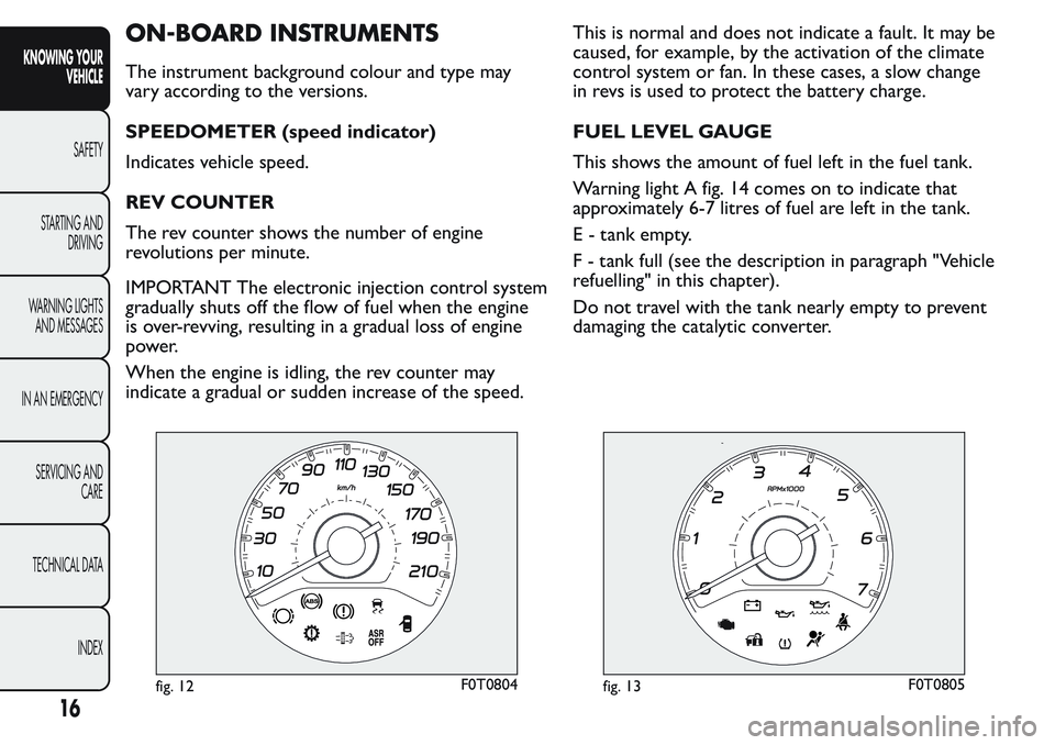
SPEEDOMETER (speed indicator)
Indicates vehicle speed.
REV COUNTER
The rev counter shows the number of engine
revolutions per minute.
IMPORTANT The electronic injection control system
gradually shuts off the flow of fuel when the engine
is over-revving, resulting in a gradual loss of engine
power.
When the engine is idling, the rev counter may
indicate a gradual or sudden increase of the speed.This is normal and does not indicate a fault. It may be
caused, for example, by the activation of the climate
control system or fan. In these cases, a slow change
in revs is used to protect the battery charge.
FUEL LEVEL GAUGE
This shows the amount of fuel left in the fuel tank.
Warning light A fig. 14 comes on to indicate that
approximately 6-7 litres of fuel are left in the tank.
E - tank empty.
F - tank full (see the description in paragraph "Vehicle
refuelling" in this chapter).
Do not travel with the tank nearly empty to prevent
damaging the catalytic converter.
fig. 12F0T0804fig. 13F0T0805
16
KNOWING YOUR
VEHICLE
SAFETY
STARTING AND
DRIVING
WARNING LIGHTS
AND MESSAGES
IN AN EMERGENCY
SERVICING AND
CARE
TECHNICAL DATA
INDEX
Page 54 of 272
MANUAL CLIMATE CONTROL
SYSTEM
(for versions/markets, where provided)
COMMANDS
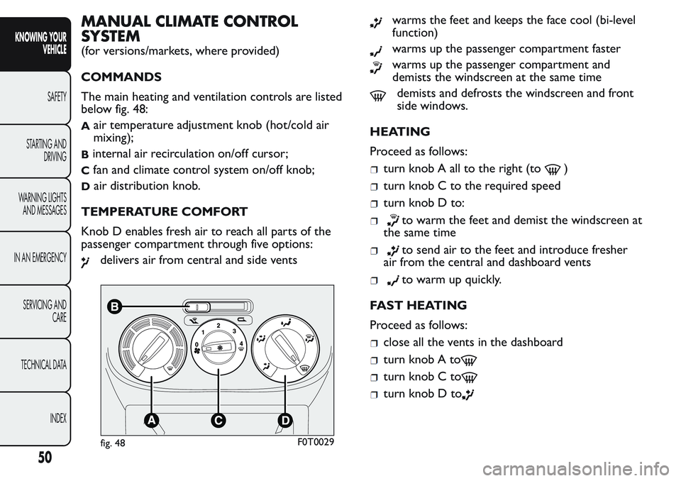
The main heating and ventilation controls are listed
below fig. 48:
Aair temperature adjustment knob (hot/cold air
mixing);
Binternal air recirculation on/off cursor;
Cfan and climate control system on/off knob;
Dair distribution knob.
TEMPERATURE COMFORT
Knob D enables fresh air to reach all parts of the
passenger compartment through five options:
delivers air from central and side vents
warms the feet and keeps the face cool (bi-level
function)
warms up the passenger compartment faster
warms up the passenger compartment and
demists the windscreen at the same time
demists and defrosts the windscreen and front
side windows.
HEATING
Proceed as follows:
turn knob A all to the right (to)
turn knob C to the required speed
turn knob D to:
to warm the feet and demist the windscreen at
the same time
to send air to the feet and introduce fresher
air from the central and dashboard vents
to warm up quickly.
FAST HEATING
Proceed as follows:
close all the vents in the dashboard
turn knob A to
turn knob C to
turn knob D to
fig. 48F0T0029
50
KNOWING YOUR
VEHICLE
SAFETY
STARTING AND
DRIVING
WARNING LIGHTS
AND MESSAGES
IN AN EMERGENCY
SERVICING AND
CARE
TECHNICAL DATA
INDEX
Page 55 of 272
RAPID WINDSCREEN AND FRONT SIDE
WINDOWS DEMISTING/DEFROSTING
(MAX-DEF function)
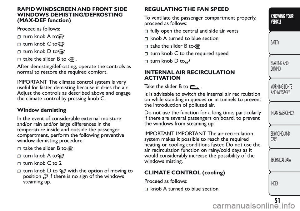
Proceed as follows:
turn knob A to
turn knob C to
turn knob D to
take the slider B to.
After demisting/defrosting, operate the controls as
normal to restore the required comfort.
IMPORTANT The climate control system is very
useful for faster demisting because it dries the air.
Adjust the controls as described above and engage
the climate control by pressing knob C.
Window demisting
In the event of considerable external moisture
and/or rain and/or large differences in the
temperature inside and outside the passenger
compartment, perform the following preventive
window demisting procedure:
take the slider B to
turn knob A to
turn knob C to 2
turn knob D towith the option of moving to
position
if there is no sign of the windows
steaming up.REGULATING THE FAN SPEED
To ventilate the passenger compartment properly,
proceed as follows:
fully open the central and side air vents
knob A turned to blue section
take the slider B to
turn knob C to the required speed
turn knob D to
INTERNAL AIR RECIRCULATION
ACTIVATION
Take the slider B to
.
It is advisable to switch the internal air recirculation
on while standing in queues or in tunnels to prevent
the introduction of polluted air.
Do not use the function for a long time, particularly
if there are several passengers on board, to prevent
the windows from steaming up.
IMPORTANT IMPORTANT The air recirculation
system makes it possible to reach the required
heating or cooling conditions faster. Do not use the
air recirculation function on rainy/cold days as it
would considerably increase the possibility of the
windows misting.
CLIMATE CONTROL (cooling)
Proceed as follows:
knob A turned to blue section
51
KNOWING YOUR
VEHICLE
SAFETY
STARTING AND
DRIVING
WARNING LIGHTS
AND MESSAGES
IN AN EMERGENCY
SERVICING AND
CARE
TECHNICAL DATA
INDEX
Page 56 of 272
turn knob C to
take the slider B to
turn knob D to
press knob C.
Adjusting cooling
Proceed as follows:
take the slider B to
turn knob A rightwards to increase the
temperature
turn knob C leftwards to reduce the fan speed.
DEMISTING/DEFROSTING OF HEATED
REAR WINDSCREEN AND DOOR MIRRORS
(for versions/markets, where provided)
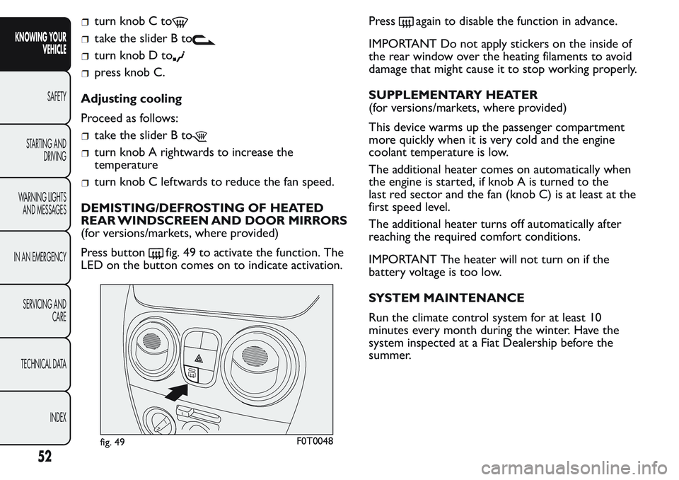
Press button
fig. 49 to activate the function. The
LED on the button comes on to indicate activation.Press
again to disable the function in advance.
IMPORTANT Do not apply stickers on the inside of
the rear window over the heating filaments to avoid
damage that might cause it to stop working properly.
SUPPLEMENTARY HEATER
(for versions/markets, where provided)
This device warms up the passenger compartment
more quickly when it is very cold and the engine
coolant temperature is low.
The additional heater comes on automatically when
the engine is started, if knob A is turned to the
last red sector and the fan (knob C) is at least at the
first speed level.
The additional heater turns off automatically after
reaching the required comfort conditions.
IMPORTANT The heater will not turn on if the
battery voltage is too low.
SYSTEM MAINTENANCE
Run the climate control system for at least 10
minutes every month during the winter. Have the
system inspected at a Fiat Dealership before the
summer.
fig. 49F0T0048
52
KNOWING YOUR
VEHICLE
SAFETY
STARTING AND
DRIVING
WARNING LIGHTS
AND MESSAGES
IN AN EMERGENCY
SERVICING AND
CARE
TECHNICAL DATA
INDEX
Page 101 of 272
ENGINE STOPPING FAILURE CONDITIONS
With the device activated, for reasons of comfort,
limiting emissions and safety, the power unit does
not stop in certain conditions, including:
engine still cold;
particularly cold external temperatures, if the
corresponding indication is provided;
battery not sufficiently charged;
particulate filter regeneration in progress (diesel
engines only);
driver's door not shut;
driver's seat belt not fastened;
reverse gear engaged (for example, for parking
manoeuvres);
automatic climate control, if a suitable thermal
comfort level has not yet been reached or to
enable MAX-DEF function;
during the first period of use, to initialize the
system.
In the above cases the warning light fig. 105 flashes
and, where provided, an information message is
displayed.
RESTARTING CONDITIONS
For reasons of comfort, limiting pollutant emissions
and safety purposes, the power unit can restart
automatically without any action on behalf of the
driver if certain conditions are met, including:
battery not sufficiently charged;
reduced braking system vacuum, e.g. following the
brake pedal being pressed repeatedly;
vehicle in motion, for example when driving on
hilly roads;
stopping the engine through the Start&Stop
system for more than about three minutes.
automatic climate control system for adjusting the
thermal comfort level or to enable MAX-DEF
function. With a gear engaged, the engine can only
be automatically restarted by fully depressing the
clutch pedal. The driver is asked to perform this
operation through the warning light fig. 105 flashing
in the instrument panel and, where provided, the
message in the display.
NoteIf the clutch is not pressed, when the three
minutes have elapsed since the engine was stopped,
the engine can be restarted only by using the key.
fig. 106F0T0426
97
KNOWING YOUR
VEHICLE
SAFETY
STARTING AND
DRIVING
WARNING LIGHTS
AND MESSAGES
IN AN EMERGENCY
SERVICING AND
CARE
TECHNICAL DATA
INDEX
Page 104 of 272
WARNING
For vehicles with robotised gearbox, in
the event of automatic engine stopping
with the car on a slope, the engine should be
restarted by moving the gear lever towards (+)
or (-) without releasing the brake pedal. For
vehicles with robotised gearbox and Hill Holder
function, in the event of automatic engine
stopping with the car on a slope, the engine
must be restarted by moving the gear lever
towards (+) or (-) without releasing the brake
pedal, so that the Hill Holder function, active
only with the engine running, becomes
available.
WARNING
If climate comfort is to be favoured, the
Star t&Stop system can be disabled,
for a continuous operation of the climate
control system.
RADIO
(for versions/markets, where provided)
Read the Supplement attached to this Owner's
Handbook for the operation of the radio with
CD/MP3 player (for versions/markets, where
provided).
LIGHT SETUP
The system consists of:
radio power wires
speaker wires in front door panels
rear speaker wires (located next to parcel shelf )
(for versions/markets, where provided)
radio housing
antenna wires.
FULL SETUP
The system consists of:
radio power wires
speaker wires in front door panels
rear speaker wires (located next to parcel shelf )
(for versions/markets, where provided)
2 full-range Ø 130 mm placed in the door;
2 full-range speakers with Ø 100 mm placed on
the parcel shelf bracket (for versions / markets,
where provided);
radio housing
100
KNOWING YOUR
VEHICLE
SAFETY
STARTING AND
DRIVING
WARNING LIGHTS
AND MESSAGES
IN AN EMERGENCY
SERVICING AND
CARE
TECHNICAL DATA
INDEX
Page 142 of 272
on fuel consumption. It is better to use a trailer to
transport particularly bulky objects.
Electric devices
Only use electrical devices for the amount of time
needed. The heated rear window, additional
headlights, windscreen/rear window wipers and
heater fan need a considerable amount of energy,
therefore increasing fuel consumption (by up to 25%
in the urban cycle).
Climate control system
The air conditioner leads to higher fuel consumption
(on average up to +20%). If the temperature outside
is not too extreme, try and use the air vents.
Spoilers
The use of non-certified spoilers may adversely affect
aerodynamics and fuel consumption.
DRIVING STYLE
The main driving styles that affect fuel consumption
are listed below.
Starting
Do not warm up the engine at low or high revs when
the vehicle is stationary; this causes the engine to
warm up more slowly, thereby increasing fuel
consumption and emissions. It is advisable to set off
immediately and slowly, avoiding high revs: this allows
the engine to warm up more quickly.Unnecessary actions
Avoid revving up when stationary at traffic lights or
before stopping the engine. The latter action, like
double declutching, is unnecessary and increases
consumption and pollution.
Gear selection
Use a higher gear as soon as traffic and road
conditions allow. Using a low gear for faster
acceleration will increase fuel consumption.
In the same way, improper use of a high gear
increases fuel consumption, emissions and engine
wear.
Top speed
Fuel consumption increases considerably with speed.
Maintain a constant speed, avoiding unnecessary
braking and acceleration, which cost in terms of both
fuel consumption and emissions.
Acceleration
Sudden acceleration has a very negative effect on fuel
consumption and emissions: accelerate gradually.
CONDITIONS OF USE
The main conditions of use which negatively affect
consumption are illustrated below.
138
KNOWING YOUR
VEHICLE
SAFETY
STARTING AND
DRIVING
WARNING LIGHTS
AND MESSAGES
IN AN EMERGENCY
SERVICING AND
CARE
TECHNICAL DATA
INDEX
Page 249 of 272
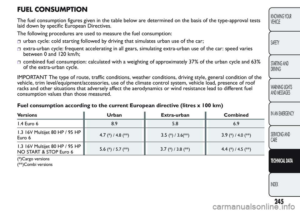
FUEL CONSUMPTION
The fuel consumption figures given in the table below are determined on the basis of the type-approval tests
laid down by specific European Directives.
The following procedures are used to measure the fuel consumption:
urban cycle: cold starting followed by driving that simulates urban use of the car;
extra-urban cycle: frequent accelerating in all gears, simulating extra-urban use of the car: speed varies
between 0 and 120 km/h;
combined fuel consumption: calculated with a weighting of approximately 37% of the urban cycle and 63%
of the extra-urban cycle.
IMPORTANT The type of route, traffic conditions, weather conditions, driving style, general condition of the
vehicle, trim level/equipment/accessories, use of the climate control system, vehicle load, presence of roof
racks and other situations that adversely affect the aerodynamics or wind resistance lead to different fuel
consumption values than those measured.
Fuel consumption according to the current European directive (litres x 100 km)
Versions Urban Extra-urban Combined
1.4 Euro 6 8.9 5.8 6.9
1.3 16V Multijet 80 HP / 95 HP
Euro 64.7
(*) / 4.8 (**)3.5(*) / 3.6(**)3.9(*) / 4.0 (**)
1.3 16V Multijet 80 HP / 95 HP
NO START & STOP Euro 65.6(*) / 5.7 (**)3.7(*) / 3.8 (**)4.4(*) / 4.5 (**)
(*)Cargo versions
(**)Combi versions
245
KNOWING YOUR
VEHICLE
SAFETY
STARTING AND
DRIVING
WARNING LIGHTS
AND MESSAGES
IN AN EMERGENCY
SERVICING AND
CARE
TECHNICAL DATA
INDEX
Page 268 of 272
Jack ................................................ 157
Jump starting ............................... 155
Keys
– Key with remote control..... 9
– Key without remote
control ..................................... 9
– Ordering additional
remote controls .................... 11
Left direction indicator
warning light.............................. 153
Lifting the vehicle....................... 187
Light beam direction .................. 80
Low battery charge warning
light ............................................. 144
Low engine oil level ................... 147
Low engine oil pressure
warning light.............................. 146
Luggage Compartment
– Emergency opening .............. 73
– Extending the boot ............... 75
– Removing the parcel shelf ... 74
– Removing the rear seat........ 75
– Repositioning the rear
seat ........................................... 75
– Securing the load................... 76
Main beam headlights................. 53
Main beam warning light .......... 153Maintenance and care -
regular checks........................... 196
Maintenance and care -
Scheduled Servicing ................. 190
Maintenance and care -
scheduled servicing plan......... 191
Manual climate control
system ......................................... 50
Manually deactivating the
front airbag and side bag ........ 125
MSR system.................................. 85
Multifunction display
– Control buttons .................... 25
– Setup menu............................. 26
– Standard screen ..................... 24
Number plate lights................... 174
Number plate lights (bulb
replacement) ............................. 174
On-board instruments............... 16
Ordering additional remote
controls ....................................... 11
Parcel shelf ................................... 74
Parking .......................................... 135
Parking lights ................................ 53
Parking sensor fault warning
light ............................................. 152
Parking sensors ........................... 93Parking sensors (warning
light) ............................................ 152
Particulate filter (DPF) ............. 105
Partitions ...................................... 39
Passenger compartment
fuse box ..................................... 183
Passenger compartment
fuse box table ........................... 185
Performance................................ 231
Pollen filter .................................. 204
Power steering fluid .................. 203
Power supply............................... 220
Pre-tensioners ............................ 110
pressure restoring...................... 165
Prolonged vehicle inactivity ..... 141
Protecting the environment .... 105
Radio ............................................. 100
Radio transmitters and
mobile phones .......................... 102
Rear ceiling light ......................... 176
Rear fog lights .............................. 62
– Warning light ......................... 153
Rear fog lights (changing a
bulb) ............................................ 172
Rear fog lights warning light .... 153
Rear light clusters ...................... 172
SAFETY
STARTING AND
DRIVING
WARNING LIGHTS
AND MESSAGES
IN AN EMERGENCY
SERVICING AND
CARE
TECHNICAL DATA
INDEX
KNOWING YOUR
VEHICLE