check FIAT FREEMONT 2016 1.G Workshop Manual
[x] Cancel search | Manufacturer: FIAT, Model Year: 2016, Model line: FREEMONT, Model: FIAT FREEMONT 2016 1.GPages: 412, PDF Size: 3.36 MB
Page 283 of 412
The dual brake system provides a reserve braking
capacity in the event of a failure to a portion of the
hydraulic system. A leak in either half of the dual brake
system is indicated by the Brake Warning Light, which
will turn on when the brake fluid level in the master
cylinder has dropped below a specified level.
The light will remain on until the cause is corrected.
NOTE:The light may flash momentarily during sharp
cornering maneuvers, which change fluid level condi-
tions. The vehicle should have service performed, and
the brake fluid level checked.
If brake failure is indicated, immediate repair is
necessary.
WARNING!
Driving a vehicle with the red brake light
on is dan
gerous. Part of the brake sys-
tem may have failed. It will take longer to stop
the vehicle. You could have a collision. Have the
vehicle checked immediately. Vehicles equipped with the Anti-Lock Brake System
(ABS), are also equipped with Electronic Brake Force
Distribution (EBD). In the event of an EBD failure, the
Brake Warning Light will turn on along with the ABS
Light. Immediate repair to the ABS system is required.
Operation of the Brake Warning Light can be checked
by turning the ignition switch from the OFF position to
the ON/RUN position. The light should illuminate for
approximately two seconds. The light should then turn
off unless the parking brake is applied or a brake fault
is detected. If the light does not illuminate, have the
light inspected by an authorized dealer.
The light also will turn on when the parking brake is
applied with the ignition switch in the ON/RUN posi-
tion.
NOTE: This light shows only that the parking brake is
applied. It does not show the degree of brake
application.
277
KNOWING
YOUR
VEHICLE
SAFETY
STARTING
AND
DRIVING
WARNING
LIGHTS
AND
MESSAGES
IN AN
EMERGENC
Y
SERVICING
AND
CARE
TECHNICAL
SPECIFICATIONS
CONTENTS
Page 284 of 412
12. Anti-Lock Brake (ABS) LightThis light monitors the Anti-Lock Brake Sys-
tem (ABS). The light will turn on when the
ignition switch is turned to the ON/RUN
position and may stay on for as long as four
seconds.
If the ABS light remains on or turns on while driving, it
indicates that the Anti-Lock portion of the brake sys-
tem is not functioning and that service is required.
However, the conventional brake system will continue
to operate normally if the Brake System Warning Light
is not on.
If the ABS light is on, the brake system should be
serviced as soon as possible to restore the benefit of
Anti-Lock brakes. Furthermore, the ABS light should
be checked frequently to assure that it is operating
properly. If the light does not turn on, have the system
checked by an authorized dealer. (Refer to “Electronic
Brake Control System” in “Knowing Your Vehicle” for
further information). 13. Fuel Cap Indicator
This symbol indicates the side of the vehicle
where the fuel filler cap is located.
14. Rear Fog Light Indicator This indicator will illuminate when the rear fog
lights are on. (Refer to “Rear Fog Lights” in
“Knowing Your Vehicle” for further
information).
15. Vehicle Security Light This light will flash rapidly for approximately
16 seconds when the vehicle security system
is arming and then flash slowly when the
system is armed. The light will also turn on
for about three seconds when the ignition switch is
first turned to ON/RUN. (Refer to “Vehicle Security
Alarm” or “Premium Security System” in “Knowing
Your Vehicle” for further information).
278
KNOWING YOUR
VEHICLE
SAFETY
STARTING AND
DRIVING
WARNING LIGHTSAND
MESSAGES
INAN
EMERGENC
Y
SERVICING AND
CARE
TECHNICAL
SPECIFICATIONS
CONTENTS
Page 289 of 412
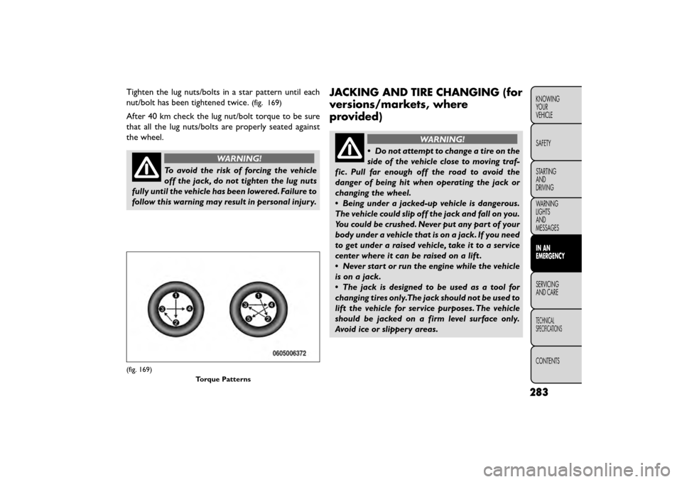
Tighten the lug nuts/bolts in a star pattern until each
nut/bolt has been tightened twice.
(fig. 169)
After 40 km check the lug nut/bolt torque to be sure
that all the lug nuts/bolts are properly seated against
the wheel.
WARNING!
To avoid the risk of forcing the vehicle
off t
he jack, do not tighten the lug nuts
fully until the vehicle has been lowered. Failure to
follow this warning may result in personal injury.
JACKING AND TIRE CHANGING (for
versions/markets, where
provided)
WARNING!
• Do not attempt to change a tire on the
si de
of the vehicle close to moving traf-
fic . Pull far enough off the road to avoid the
danger of being hit when operating the jack or
changing the wheel.
• Being under a jacked-up vehicle is dangerous.
The vehicle could slip off the jack and fall on you.
You could be crushed. Never put any part of your
body under a vehicle that is on a jack. If you need
to get under a raised vehicle, take it to a service
center where it can be raised on a lift .
• Never start or run the engine while the vehicle
is on a jack.
• The jack is designed to be used as a tool for
changing tires only.The jack should not be used to
lift the vehicle for service purposes. The vehicle
should be jacked on a firm level surface only.
Avoid ice or slippery areas.
(fig. 169)
Torque Patterns
283
KNOWING
YOUR
VEHICLE
SAFETY
STARTING
AND
DRIVING
WARNING
LIGHTS
AND
MESSAGES
IN AN
EMERGENCY
SERVICING
AND
CARE
TECHNICAL
SPECIFICATIONS
CONTENTS
Page 296 of 412
NOTE:
• For vehicles so equipped, do not attempt to install acenter cap or wheel cover on the compact spare.
• Refer to “Compact Spare Tire” and to “Limited-Use Spare” under “Tires — General Information” in
“Technical Specifications” for additional warnings,
cautions, and information about the spare tire, its
use, and operation.
7. Install the wheel nuts with the cone-shaped end of the nut toward the wheel. Lightly tighten the wheel
nuts.
WARNING!
To avoid the risk of forcing the vehicle
off t
he jack, do not tighten the wheel
nuts fully until the vehicle has been lowered.
Failure to follow this warning may result in per-
sonal injury.
8. Lower the vehicle by turning the jack screw coun- terclockwise with the jack handle. 9. Finish tightening the lug nuts. Push down on the
wrench while at the end of the handle for increased
leverage. Tighten the lug nuts in a star pattern until
each nut has been tightened twice. Refer to “Torque
Specifications” in this section for proper lug nut
torque. If in doubt about the correct tightness, have
them checked with a torque wrench by your autho-
rized dealer or service station.
10. Lower the jack to its fully closed position.
11. Place the deflated (flat) tire in the cargo area. Do
not stow the deflated tire in the spare tire
stowage location. Have the deflated (flat) tire
repaired or replaced as soon as possible.
12. To stow the winch cable and retainer, fit the assembled jack-handle over the winch drive nut.
Rotate the jack-handle assembly clockwise until
you hear the winch mechanism click three times. It
cannot be over tightened.
13. Stow the jack-handle and jack. Remove the wheel blocks from the vehicle and release the park brake.
14. Check the tire pressure as soon as possible. Adjust the tire pressure as required.
290
KNOWING YOUR
VEHICLE
SAFETY
STARTING AND
DRIVING
WARNING LIGHTSAND
MESSAGES
IN AN
EMERGENCY
SER VICING
AND
CARE
TECHNICAL
SPECIFICATIONS
CONTENTS
Page 298 of 412

6. Finish tightening the lug nuts. Push down on thewrench while at the end of the handle for increased
leverage. Tighten the lug nuts in a star pattern until
each nut has been tightened twice. For the correct
lug nut torque refer to Torque Specifications in this
section. If in doubt about the correct tightness, have
them checked with a torque wrench by your autho-
rized dealer or service station.
7. After 40 km check the lug nut torque with a torque wrench to ensure that all lug nuts are properly
seated against the wheel.
Vehicles Without Wheel Covers
1. Mount the road tire on the axle.
2. Install the remaining lug nuts with the cone shaped end of the nut toward the wheel. Lightly tighten the
lug nuts.WARNING!
To avoid the risk of forcing the vehicle
off t
he jack, do not tighten the lug nuts
fully until the vehicle has been lowered. Failure to
follow this warning may result in personal injury.
3. Lower the vehicle to the ground by turning the jack handle counterclockwise.
4. Finish tightening the lug nuts. Push down on the wrench while at the end of the handle for increased
leverage. Tighten the lug nuts in a star pattern until
each nut has been tightened twice. For proper lug
nut torque refer to Torque Specifications in this
secton. If in doubt about the correct tightness, have
them checked with a torque wrench by your autho-
rized dealer or service station.
5. After 40 km check the lug nut torque with a torque wrench to ensure that all lug nuts are properly
seated against the wheel.
292
KNOWING YOUR
VEHICLE
SAFETY
STARTING AND
DRIVING
WARNING LIGHTSAND
MESSAGES
IN AN
EMERGENCY
SER VICING
AND
CARE
TECHNICAL
SPECIFICATIONS
CONTENTS
Page 303 of 412
NOTE:Do not remove foreign objects (e.g., screws or
nails) from the tire.
(C) Injecting Tire Service Kit Sealant Into The
Deflated Tire:
• Always start the engine before turning ON the Tire Service Kit.
NOTE: Manual transmission vehicles must have the
parking brake engaged and the shift lever in NEUTRAL.
• After pressing the Power Button (4), the sealant (white fluid) will flow from the Sealant Bottle (1)
through the Sealant Hose (6) and into the tire.
NOTE: Sealant may leak out through the puncture in
the tire.
If the sealant (white fluid) does not flow within 0
– 10 seconds through the Sealant Hose (6):
1. Press the Power Button (4) to turn Off the Tire Service Kit. Disconnect the Sealant Hose (6) from
the valve stem. Make sure the valve stem is free of
debris. Reconnect the Sealant Hose (6) to the valve
stem. Check that the Mode Select Knob (5) is in the
Sealant Mode position and not Air Mode. Press the
Power Button (4) to turn On the Tire Service Kit. 2. Connect the Power Plug (8) to a different 12 Volt
power outlet in your vehicle or another vehicle, if
available. Make sure the engine is running before
turning ON the Tire Service Kit.
3. The Sealant Bottle (1) may be empty due to previ- ous use. Call for assistance.
NOTE: If the Mode Select Knob (5) is on Air Mode
and the pump is operating, air will dispense from the
Air Pump Hose (7) only, not the Sealant Hose (6).
If the sealant (white fluid) does flow through the
Sealant Hose (6):
1. Continue to operate the pump until sealant is no longer flowing through hose (typically takes 30 - 70
seconds). As the sealant flows through the Sealant
Hose (6), the Pressure Gauge (3) can read as high as
4.8 Bar. The Pressure Gauge (3) will decrease
quickly from approximately 4.8 Bar to the actual tire
pressure when the Sealant Bottle (1) is empty.
2. The pump will start to inject air into the tire immediately after the Sealant Bottle (1) is empty.
Continue to operate the pump and inflate the tire
to the pressure indicated on the tire pressure label
on the driver-side latch pillar (recommended pres-
sure). Check the tire pressure by looking at the
Pressure Gauge (3).
297
KNOWING
YOUR
VEHICLE
SAFETY
STARTING
AND
DRIVING
WARNING
LIGHTS
AND
MESSAGES
IN AN
EMERGENCY
SER VICING
AND
CARE
TECHNICAL
SPECIFICATIONS
CONTENTS
Page 305 of 412
(E) After Driving:
Pull over to a safe location. Refer to “Whenever You
Stop to Use Tire Service Kit” before continuing.
1. Turn the Mode Select Knob (5) to the Air Modeposition.
2. Uncoil the power plug and insert the plug into the vehicle's 12 Volt power outlet.
3. Uncoil the Air Pump Hose (7) (black in color) and screw the fitting at the end of hose (7) onto the
valve stem.
4. Check the pressure in the tire by reading the Pres- sure Gauge (3).
If tire pressure is less than 1.3 Bar, the tire is too
badly damaged. Do not attempt to drive the vehicle
further. Call for assistance.
If the tire pressure is 1.3 bar or higher:
1. Press the Power Button (4) to turn on Tire Service Kit and inflate the tire to the pressure indicated on
the tire and loading information label on the driver-
side door opening. NOTE:
If the tire becomes over-inflated, press the
Deflation Button to reduce the tire pressure to the
recommended inflation pressure before continuing.
2. Disconnect the Tire Service Kit from the valve stem, reinstall the cap on the valve stem and unplug
from 12 Volt outlet.
3. Place the Tire Service Kit in its proper storage area in the vehicle.
4. Have the tire inspected and repaired or replaced at the earliest opportunity at an authorized dealer or
tire service center.
5. Replace the Sealant Bottle (1) and Sealant Hose (6) assembly at your authorized dealer as soon as pos-
sible. Refer to “(F) Sealant Bottle and Hose Replace-
ment.”
NOTE: When having the tire serviced, advise the
authorized dealer or service center that the tire has
been sealed using the Tire Service Kit.
299
KNOWING
YOUR
VEHICLE
SAFETY
STARTING
AND
DRIVING
WARNING
LIGHTS
AND
MESSAGES
IN AN
EMERGENCY
SER VICING
AND
CARE
TECHNICAL
SPECIFICATIONS
CONTENTS
Page 328 of 412
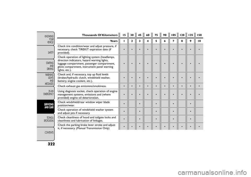
Thousands Of Kilometers 15 30 45 60 75 90 105 120 135 150Years 1 2 3 4 5678910
Check tire condition/wear and adjust pressure, if
necessary, check TIREKIT expiration date (if
provided). ••••••••••
Check operation of lighting system (headlamps,
direction indicators, hazard warning lights,
luggage compartment, passenger compartment,
glove compartment, instrument panel warning
lights, etc.). ••••••••••
Check and, if necessary, top up fluid levels
(brakes/hydraulic clutch, windshield washer,
battery, engine coolant, etc.). ••••••••••
Check exhaust gas emissions/smokiness. • • • • ••••••
Using diagnosis socket, check operation of engine
management systems, emissions and (where
provided) engine oil deterioration. ••••••••••
Check windshield/rear window wiper blade
position/wear. •••••
Check operation of windshield washer system
and adjust jets if necessary. •••••
Check cleanliness of hood and tailgate locks and
cleanliness and lubrication of linkages. •••••
Check the parking brake lever stroke and adjust
it, if necessary. (Manual Transmission Only) ••••••••••
322
KNOWING
YOUR
VEHICLE
SAFETY
STARTING AND
DRIVING
WARNING LIGHTSAND
MESSAGES
IN AN
EMERGENCY
SERVICINGAND C ARE
TECHNICAL
SPECIFICATIONS
CONTENTS
Page 329 of 412
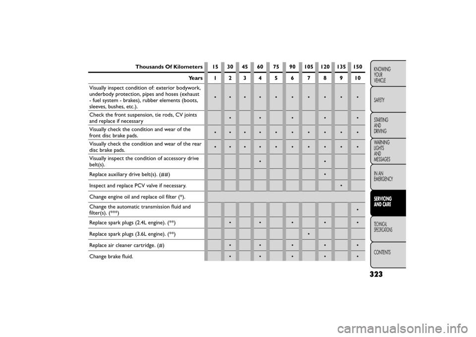
Thousands Of Kilometers 15 30 45 60 75 90 105 120 135 150Years 1 2 3 4 5678910
Visually inspect condition of: exterior bodywork,
underbody protection, pipes and hoses (exhaust
- fuel system - brakes), rubber elements (boots,
sleeves, bushes, etc.). ••••••••••
Check the front suspension, tie rods, CV joints
and replace if necessary •••••
Visually check the condition and wear of the
front disc brake pads. ••••••••••
Visually check the condition and wear of the rear
disc brake pads. ••••••••••
Visually inspect the condition of accessory drive
belt(s). ••
Replace auxiliary drive belt(s). (##) •
Inspect and replace PCV valve if necessary. •
Change engine oil and replace oil filter (*).
Change the automatic transmission fluid and
filter(s). (***) •
Replace spark plugs (2.4L engine). (**) • • • • •
Replace spark plugs (3.6L engine). (**) •
Replace air cleaner cartridge. (#) • • • • •
Change brake fluid. • • • • •
323
KNOWING
YOUR
VEHICLE
SAFETY
STARTING
AND
DRIVING
WARNING
LIGHTS
AND
MESSAGES
IN AN
EMERGENCY
SERVICING
AND C ARE
TECHNICAL
SPECIFICATIONS
CONTENTS
Page 330 of 412
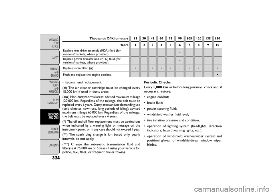
Thousands Of Kilometers 15 30 45 60 75 90 105 120 135 150Years 1 2 3 4 5678910
Replace rear drive assembly (RDA) fluid (for
versions/markets, where provided). •
Replace power transfer unit (PTU) fluid (for
versions/markets, where provided). •
Replace cabin filter. (#) ◦•◦ • ◦ •◦•◦•
Flush and replace the engine coolant. •
◦Recommend replacement.
(#) The air cleaner cartridge must be changed every
15,000 km if used in dusty areas.
(##)
Non-dusty/normal areas: advised maximum mileage
120,000 km. Regardless of the mileage, the belt must be
replaced every 6 years. Dusty areas and/or demanding use
(cold climates, town use, long periods of idling): advised
maximum mileage 60,000 km. Regardless of the mileage,
the belt must be replaced every 4 years.
(*)The oil and oil filter replacement must be carried out
when indicated by a warning light or message on the
instrument panel, or in any case should not exceed 1 year.
(**) The spark plug change is km based only, yearly
intervals do not apply.
(***) Change the automatic transmission fluid and
filter(s) at 75,000 km or 5 years if using your vehicle for
police, taxi, fleet, or frequent trailer towing. Periodic Checks
Every
1,000 km or before long journeys, check and, if
necessary, restore:
• engine coolant;
• brake fluid;
• power steering fluid;
• windshield washer fluid level;
• tire inflation pressure and condition;
• operation of lighting system (headlights, direction indicators, hazard warning lights, etc.);
• operation of windshield washer/wiper system and positioning/wear of windshield/rear window wiper
blades.
324
KNOWING YOUR
VEHICLE
SAFETY
STARTING AND
DRIVING
WARNING LIGHTSAND
MESSAGES
IN AN
EMERGENCY
SERVICINGAND C ARE
TECHNICAL
SPECIFICATIONS
CONTENTS