clock FIAT TEMPRA 1988 Service And Repair Manual
[x] Cancel search | Manufacturer: FIAT, Model Year: 1988, Model line: TEMPRA, Model: FIAT TEMPRA 1988Pages: 171, PDF Size: 18.05 MB
Page 7 of 171
Fluid levels (if included) are monitored by LEDs f, o and
p, indicating the levels of the fluid reservoirs.
A red LED illuminates at the position on the check panel
corresponding to a side door or a hatchback/tailgate
that is not properly closed.
SIDE AND TAIL LIGHTS
When the side and tail lights are turned on, the check
panel monitors the light bulbs, fuses and circuits.
• LED g monitors the front side lights.
• LED i monitors the tail lights.
If one of the two fuses protecting the following bulbs
blows, LEDs g, i, and m illuminate.
NUMBER PLATE LIGHTS
• LED m indicates when one or both of the number
plate light bulbs have burnt out.
REAR FOG LIGHTS
• When the fog-guard lights are turned on, LED h
monitors the light bulbs.
• When the fuse blows or a circuit malfunction occurs,
LED h illuminates, but not the panel indicator.
STOP LIGHTS
If one or both stop lights burn out, the fuse blows or a
circuit malfunction occurs, LED I or n illuminates when
braking.
• LED n monitors the left stop light.
• LED I monitors the right stop light.
If both bulbs burn out at the same time or brake pedal
switch malfunction occurs, both LEDs I and n
illuminate.
ENGINE OIL LEVEL
• LED f illuminates when the engine oil level is low (key
at MAR,engine not running).
The oil level monitoring system does not operate when
the engine is running. If the oil level warning LED
illuminates when driving, a circuit sensor malfunction
has occurred.
When starting the car on a hill or within 10 minutes of
switching off the engine the warning light may
illuminate (event will be stored in system memory). Start
the engine again on level ground to ensure the oil level
is sufficient.
COOLANT
A low coolant level is indicated by LED o (key at MAR).
The LED also illuminates when a sensor or circuit
malfunction occurs.
WINDSCREEN AND REAR SCREEN WASH LEVELS
• LED p illuminates (key at MAR) when the level in the
windscreen or rear screen wash reservoirs are low.
• The LED also indicates when a circuit or sensor
malfunction occurs.
• 5. HE ATI IMG AMD VENTILATION
CONTROLS
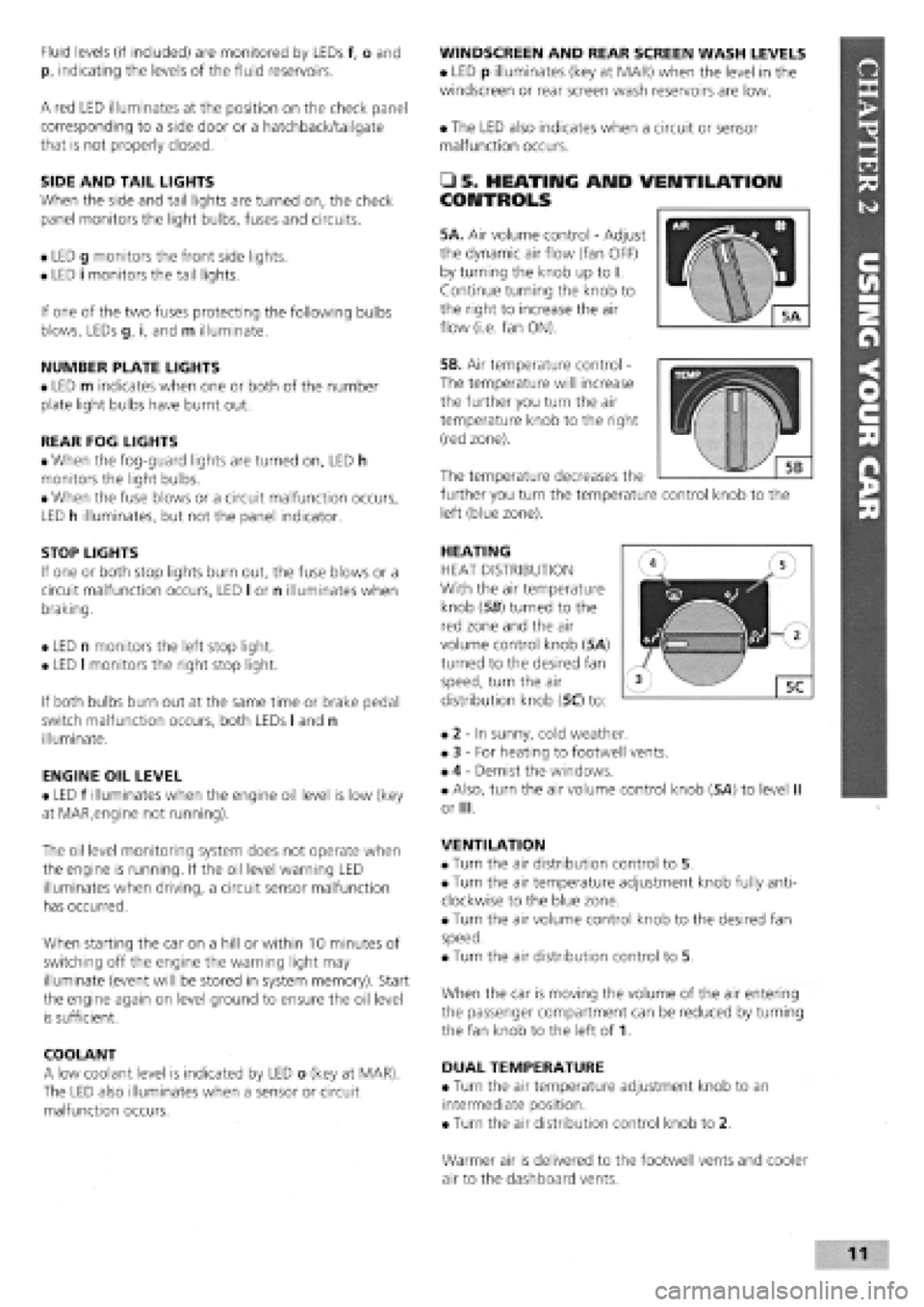
5A. Air volume control
-
Adjust
the dynamic air flow (fan OFF)
by turning the knob up to I.
Continue turning the knob to
the right to increase the air
flow (i.e. fan ON).
5B. Air temperature control -
The temperature will increase
the further you turn the air
temperature knob to the right
(red zone).
HEATING
HEAT DISTRIBUTION
With the air temperature
knob (56) turned to the
red zone and the air
volume control knob (5A)
turned to the desired fan
speed, turn the air
distribution knob (5C) to:
• 2
-
In sunny, cold weather.
• 3
-
For heating to footwell vents.
• 4
-
Demist the windows.
• Also, turn the air volume control knob (5A) to level II
or III.
VENTILATION
• Turn the air distribution control to 5.
• Turn the air temperature adjustment knob fully anti-
clockwise to the blue zone.
• Turn the air volume control knob to the desired fan
speed.
• Turn the air distribution control to 5.
When the car is moving the volume of the air entering
the passenger compartment can be reduced by turning
the fan knob to the left of 1.
DUAL TEMPERATURE
• Turn the air temperature adjustment knob to an
intermediate position.
• Turn the air distribution control knob to 2.
The temperature decreases the
further you turn the temperature control knob to the
left (blue zone).
Warmer air is delivered to the footwell vents and cooler
air to the dashboard vents.
Page 11 of 171
SAFETY FIRST!
If an air bag has been fitted to your vehicle:
• DO NOT apply stickers or any other objects to
the steering wheel as this may restrict the
operation of the air bag.
• NEVER travel with anything on your lap or in
front of your chest
• NEVER drive with a cigarette, pipe, pen or any
other object in your mouth.
• 12. INTERIOR LIGHTS
COURTESY LIGHT
On most models the courtesy light is positioned in the
centre of the roof.
• With the light switch in the central position the light
turns on when either of the front doors is opened.
• When the switch is in the right position the light
remains on.
• With the switch in the left position the light is
switched off.
• 13. SUNROOF OPERATION
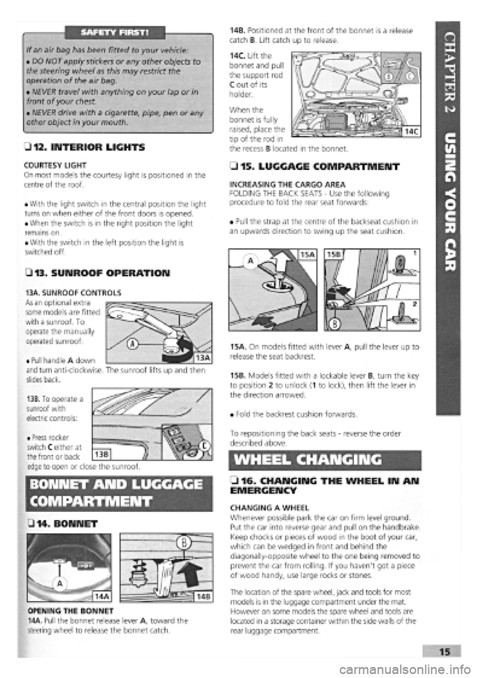
14B. Positioned at the front of the bonnet is a release
catch B. Lift catch up to release.
14C. Lift the
bonnet and pull
the support rod
C out of its
holder.
When the
• 15. LUGGAGE COMPARTMENT
INCREASING THE CARGO AREA
FOLDING THE BACK SEATS
-
Use the following
procedure to fold the rear seat forwards:
• Pull the strap at the centre of the backseat cushion in
an upwards direction to swing up the seat cushion.
15A. On models fitted with lever A, pull the lever up to
release the seat backrest.
15B. Models fitted with a lockable lever B, turn the key
to position 2 to unlock (1 to lock), then lift the lever in
the direction arrowed.
• Fold the backrest cushion forwards.
BONNET AND LUGGAGE
L 2 . fj§
• 14 .BONNET
OPENING THE BONNET
14A. Pull the bonnet release lever A, toward the
steering wheel to release the bonnet catch.
To repositioning the back seats
-
reverse the order
described above.
WHEEL CHANGING
• 16. CHANGING THE WHEEL IN AN
EMERGENCY
CHANGING A WHEEL
Whenever possible park the car on firm level ground.
Put the car into reverse gear and pull on the handbrake.
Keep chocks or pieces of wood in the boot of your car,
which can be wedged in front and behind the
diagonally-opposite wheel to the one being removed to
prevent the car from rolling. If you haven't got a piece
of wood handy, use large rocks or stones.
The location of the spare wheel, jack and tools for most
models is in the luggage compartment under the mat.
However on some models the spare wheel and tools are
located in a storage container within the side walls of the
rear luggage compartment.
bonnet is fully
raised, place the
tip of the rod in
the recess B located in the bonnet.
• Pull handle A down
and turn anti-clockwise,
slides back.
13B. To operate a
sunroof with
electric controls:
13A. SUNROOF CONTROLS
As an optional extra
some models are fitted
with a sunroof. To
operate the manually
operated sunroof:
The sunroof lifts up and then
• Press rocker
switch C either at
the front or back
edge to open or close the sunroof.
Z3
Page 26 of 171
PART C: VEHICLE RAISED OFF THE GROUND
Bodywork Structure
01
.
Any sharp edges on the external bodywork, caused by damage or corrosion will cause the vehicle to fail.
02 . Check all load bearing areas for corrosion. Open the doors and check the sills inside and out, above and below. Any corrosion in structural metalwork within 30 cm (12 in.) of seat belt mounting, steering and suspension attachment points will cause the vehicle to fail.
Wheels and Tyres
Under the Front of the
Car
You will need to support the front of the car on axle stands with the rear wheels firmly chocked in both directions.
OE . Have your helper turn the steering from lock to lock and check that the steering turns smoothly and that the brake hoses or pipes do not contact the wheel, tyre or any part of the steering or suspension.
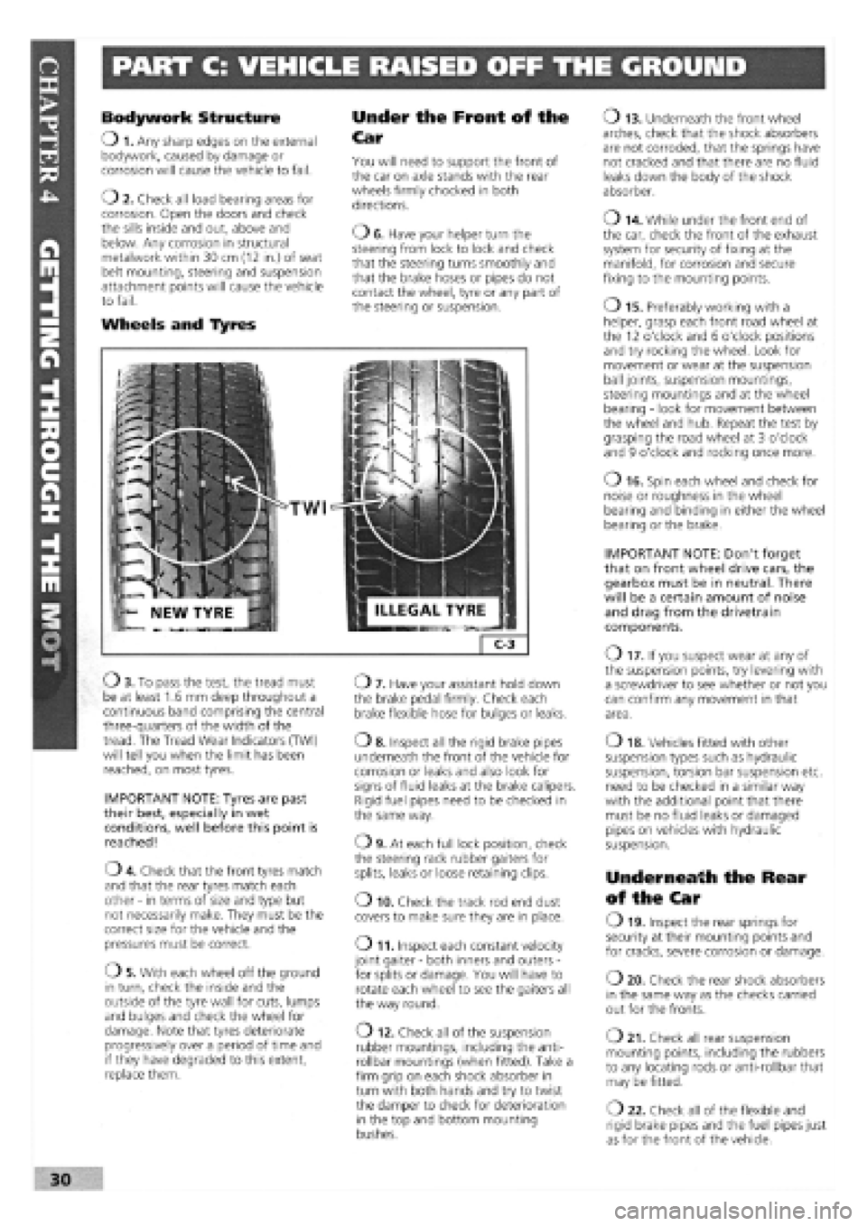
TWI
Ob . To pass the test, the tread must be at least 1.6 mm deep throughout a continuous band comprising the central three-quarters of the width of the tread. The Tread Wear Indicators (TWI) will tell you when the limit has been reached, on most tyres.
IMPORTANT NOTE: Tyres are past their best, especially in wet conditions, well before this point is reached!
04 . Check that the front tyres match and that the rear tyres match each other
-
in terms of size and type but not necessarily make. They must be the correct size for the vehicle and the pressures must be correct.
05 . With each wheel off the ground in turn, check the inside and the outside of the tyre wall for cuts, lumps and bulges and check the wheel for damage. Note that tyres deteriorate progressively over a period of time and if they have degraded to this extent, replace them.
07 . Have your assistant hold down the brake pedal firmly. Check each brake flexible hose for bulges or leaks.
o 8. Inspect all the rigid brake pipes underneath the front of the vehicle for corrosion or leaks and also look for signs of fluid leaks at the brake calipers. Rigid fuel pipes need to be checked in the same way.
09 . At each full lock position, check the steering rack rubber gaiters for splits, leaks or loose retaining clips.
o 10. Check the track rod end dust covers to make sure they are in place.
o 11. Inspect each constant velocity joint gaiter
-
both inners and outers
-
for splits or damage. You will have to rotate each wheel to see the gaiters all the way round.
O 12. Check all of the suspension rubber mountings, including the anti-rollbar mountings (when fitted). Take a firm grip on each shock absorber in turn with both hands and try to twist the damper to check for deterioration in the top and bottom mounting bushes.
o 13. Underneath the front wheel arches, check that the shock absorbers are not corroded, that the springs have not cracked and that there are no fluid leaks down the body of the shock absorber.
o 14. While under the front end of the car, check the front of the exhaust system for security of fixing at the manifold, for corrosion and secure fixing to the mounting points.
o 15. Preferably working with a helper, grasp each front road wheel at the 12 o'clock and 6 o'clock positions and try rocking the wheel. Look for movement or wear at the suspension ball joints, suspension mountings, steering mountings and at the wheel bearing
-
look for movement between the wheel and hub. Repeat the test by grasping the road wheel at 3 o'clock and 9 o'clock and rocking once more.
o 16. Spin each wheel and check for noise or roughness in the wheel bearing and binding in either the wheel bearing or the brake.
IMPORTANT NOTE: Don't forget that on front wheel drive cars, the gearbox must be in neutral. There will be a certain amount of noise and drag from the drivetrain components.
O 17. If you suspect wear at any of the suspension points, try levering with a screwdriver to see whether or not you can confirm any movement in that area.
o 18. Vehicles fitted with other suspension types such as hydraulic suspension, torsion bar suspension etc. need to be checked in a similar way with the additional point that there must be no fluid leaks or damaged pipes on vehicles with hydraulic suspension.
Underneath the Rear
of the Car
O 19. Inspect the rear springs for security at their mounting points and for cracks, severe corrosion or damage.
o 20. Check the rear shock absorbers in the same way as the checks carried out for the fronts.
o 21. Check all rear suspension mounting points, including the rubbers to any locating rods or anti-rollbar that may be fitted.
O 22. Check all of the flexible and rigid brake pipes and the fuel pipes just as for the front of the vehicle.
30
Page 31 of 171
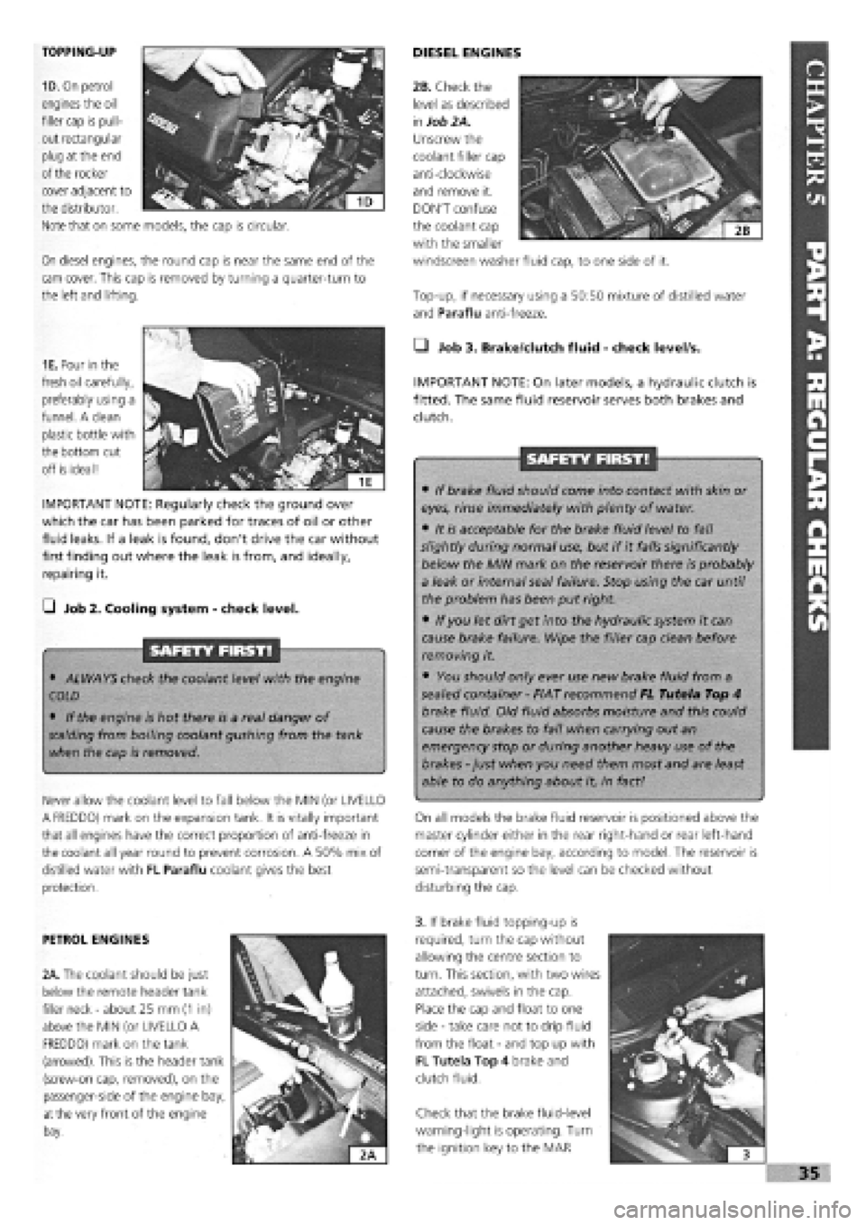
TOPPING-UP
1D. On petrol
engines the oil
filler cap is pull-
out rectangular
plug at the end
of the rocker
On diesel engines, the round cap is near the same end of the
cam cover. This cap is removed by turning a quarter-turn to
the left and lifting.
DIESEL ENGINES
Top-up, if necessary using a 50:50 mixture of distilled water
and Paraflu anti-freeze.
cover adjacent to
the distributor.
Note that on some models, the cap is circular.
1E. Pour in the
fresh oil carefully,
preferably using a
funnel. A clean
plastic bottle with
the bottom cut
off is ideal!
IMPORTANT NOTE: Regularly check the ground over
which the car has been parked for traces of oil or other
fluid leaks. If a leak is found, don't drive the car without
first finding out where the leak is from, and ideally,
repairing it.
G Job 2. Cooling system
-
check level.
SAFETY FIRST!
• ALWAYS check the coolant level with the engine
COLD
• If the engine is hot there is a real danger of
scalding
from boiling coolant gushing from the tank
when the cap is removed.
Never allow the coolant level to fall below the MIN (or UVELLO
A FREDDO) mark on the expansion tank. It is vitally important
that all engines have the correct proportion of anti-freeze in
the coolant all year round to prevent corrosion. A 50% mix of
distilled water with FL Paraflu coolant gives the best
protection.
• Job 3. Brake/dutch fluid
-
check level/s.
IMPORTANT NOTE: On later models, a hydraulic clutch is
fitted. The same fluid reservoir serves both brakes and
clutch.
SAFETY FIRST!
• If brake fluid should come into contact with skin or
eyes, rinse immediately with plenty of water.
• It is acceptable for the brake fluid level to fall
slightly during normal use, but if it falls significantly
below the MIN mark on the reservoir there is probably
a leak or internal seal failure. Stop using the car until
the problem has been put right.
• If you let dirt get into the hydraulic system it can
cause brake failure. Wipe the filler cap clean before
removing it.
• You should only ever use new brake fluid from a
sealed container
-
FIAT recommend FL Tutela Top 4
brake fluid. Old fluid absorbs moisture and this could
cause the brakes to fail when carrying out an
emergency stop or during another heavy use of the
brakes
-
just when you need them most and are least
able to do anything about it, in fact!
On all models the brake fluid reservoir is positioned above the
master cylinder either in the rear right-hand or rear left-hand
corner of the engine bay, according to model. The reservoir is
semi-transparent so the level can be checked without
disturbing the cap.
PETROL ENGINES
2A. The coolant should be just
below the remote header tank
filler neck
-
about 25 mm
(1
in)
above the MIN (or UVELLO A
FREDDO) mark on the tank
(arrowed). This is the header tank
(screw-on cap, removed), on the
passenger-side of the engine bay,
at
the very front of the engine
bay.
3. If brake fluid topping-up is
required, turn the cap without
allowing the centre section to
turn. This section, with two wires
attached, swivels in the cap.
Place the cap and float to one
side
-
take care not to drip fluid
from the float
-
and top up with
FL Tutela Top 4 brake and
clutch fluid.
Check that the brake fluid-level
warning-light is operating. Turn
the ignition key to the MAR
I
i 3
»35
2B. Check the
level as described
in
Job 2A.
Unscrew the
coolant filler cap
anti-clockwise
and remove it.
DON'T confuse
the coolant cap
with the smaller
windscreen washer fluid cap, to one side of it.
Page 33 of 171
• Whenever a light fails to
work, check its fuse before
replacing the bulb.
• A blown bulb often causes a fuse to 'go' in
sympathy.
hands, looking and feeling for any bulges, tears or splits in the
tyre walls, especially the inner sidewalls. (See Job 59 for spare
tyre checks.)
H INSIDE INFORMATION: In time, rubber deteriorates,
increasing the risk of a blow-out. Keep your eye on the
sidewalls of older tyres. If you see any cracking, splits or
other damage scrap the tyre. If you're not sure, consult
your FIAT dealer or tyre specialist. Q
_) Job 7. Check lights/change bulbs.
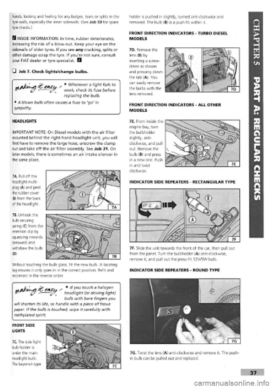
7A. Pull off the
headlight multi-
plug (A) and peel
the rubber cover
(B) from the back
of the headlight.
7B. Unhook the
bulb securing
spring (C) from the
retention clip by
squeezing inwards
(arrowed) and
withdraw the bulb
(D).
Without touching the bulb glass, fit the new bulb. A locating
tag ensures it only goes in in the correct position. Refit and
reconnect in the reverse order.
HEADLIGHTS
IMPORTANT NOTE: On Diesel models with the air filter
mounted behind the right-hand headlight unit, you will
first have to remove the large hose, unscrew the clamp
nut and take off the air filter assembly. See Job 31. On
later models, there is sometimes an air intake silencer in
the same place.
7F. Slide the unit towards the front of the car, then pull out
from the panel. Turn the bulbholder (A) anti-clockwise,
remove it, and pull out the press-fit 12V/5W bulb.
INDICATOR SIDE REPEATERS
-
ROUND TYPE
holder is pushed in slightly, turned anti-clockwise and
removed. The bulb (B) is a push-fit within it.
FRONT DIRECTION INDICATORS
-
TURBO DIESEL
MODELS
7D. Remove the
lens (B) by
inserting a screw-
driver as shown
and pressing down
the tab (A). You
can easily remove
the bulbs with the
lens removed.
FRONT DIRECTION INDICATORS
-
ALL OTHER
MODELS
7E. From inside the
engine bay, turn
the bulbholder
slightly, anti-
clockwise, and pull
out. Remove the
bulb (B) and press
in a new one. Push
in and twist
clockwise.
INDICATOR SIDE REPEATERS
-
RECTANGULAR TYPE
CAS / * touc^ a halogen
• headlight (or driving light)
bulb with bare fingers you
will
shorten its life, so handle with a piece of
tissue
paper. If the bulb is touched, wipe it carefully with
methylated spirit.
FRONT SIDE
LIGHTS
7C.
The side light
bulb holder is
under the main
headlight bulb.
The bayonet-type
7G. Twist the lens (A) anti-clockwise and remove it. The push-
in bulb can be pulled out and replaced.
Page 34 of 171
ruvj
uivjh I
uuluj
^ Use a magnetic screw-
driver or place some thick
grease on the end of the
screwdriver to prevent the screws from falling
-
especially when replacing the lens.
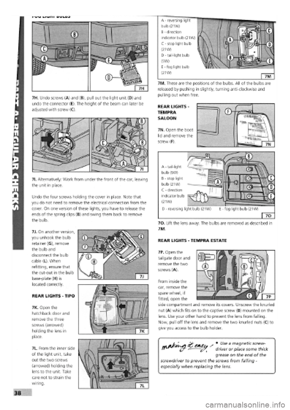
7H. Undo screws (A) and (B), pull out the light unit (D) and
undo the connector (E). The height of the beam can later be
adjusted with screw (C).
71. Alternatively: Work from under the front of the car, leaving
the unit in place.
Undo the four screws holding the cover in place. Note that
you do not need to remove the electrical connection from the
cover. On one version of these lights, you have to release the
ends of the spring clips (B) and swing them back to remove
the bulb.
7J. On another version,
you unhook the bulb
retainer (G), remove
the bulb and
disconnect the bulb
cable (L). When
refitting, ensure that
the cut-out in the bulb
base-plate (H) is
located correctly.
REAR LIGHTS
-
TIPO
7K. Open the
hatchback door and
remove the three
screws (arrowed)
holding the lens in
place.
7L. From the inner side
of the light unit, take
out the two screws
(arrowed) holding the
lens to the unit. Take
care not to strain the
wiring.
7M. These are the positions of the bulbs. All of the bulbs are
released by pushing in slightly, turning anti-clockwise and
pulling out when free.
REAR LIGHTS -
TEMPRA
SALOON
7N. Open the boot
lid and remove the
screw (F).
-fog light bulb (21W)
70
70. Lift the lens away. The bulbs are removed as described in
7M.
REAR LIGHTS
-
TEMPRA ESTATE
7P. Open the
tailgate door and
remove the two
screws (A).
From inside the
car, remove the
spare wheel, if
fitted, open the
side compartment and remove its covers. Unscrew the knurled
nut (A) which fits on to the captive screw (B) mounted on the
lens. Use your other hand to prevent the lens from falling.
Now, pull off the lens and remove the two knurled nuts (C) to
give you access to the bulb holder.
A - tail-light
bulb (5W)
B - stop light
bulb (21W)
C - direction
indicator bulb
(21W)
D - reversing light bulb (21W) E
A - reversing
bulb (21W)
B - direction
indicator bulb (21W)
C - stop light bulb
(21W)
D
-
tail-light bulb
(5W)
E - fog light bulb
(21W)
Page 45 of 171
FACT FILE: DIGIPLEX DISTRIBUTOR
REMOVAL
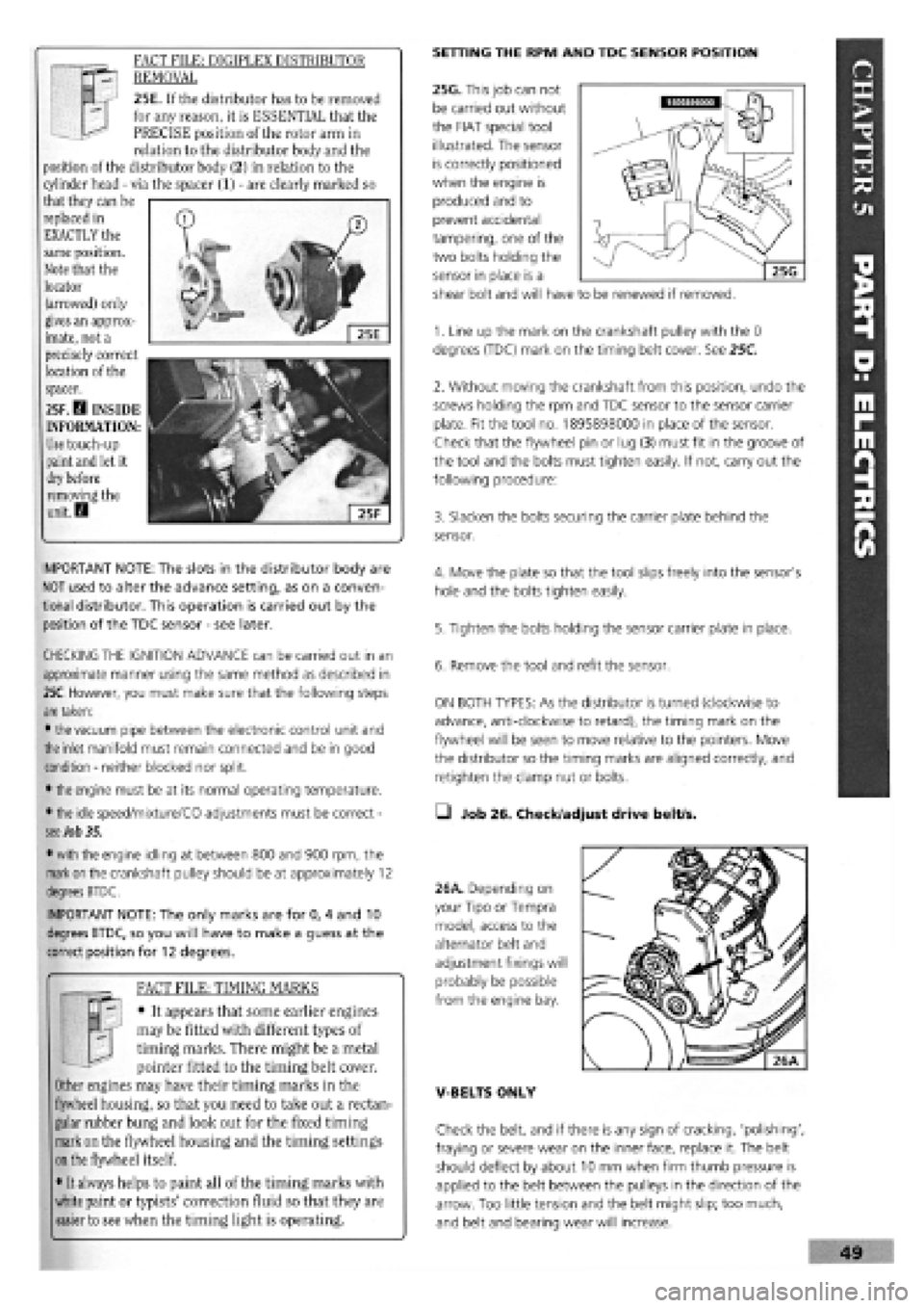
25E. If the distributor has to be removed
for any reason, it is ESSENTIAL that the
PRECISE position of the rotor arm in
relation to the distributor body and the
position of the distributor body (2) in relation to the
cylinder head
-
via the spacer (1)
-
are clearly marked so
that they can be
replaced in
EXACTLY the
same position.
Note that the
locator
(arrowed) only
gives an approx-
imate, not a
precisely correct
location of the
spacer.
25F. D INSIDE
INFORMATION:
Use
touch-up
paint
and
let it
dry before
removing the
unit. D
SETTING THE RPM AND TDC SENSOR POSITION
25G. This job can not
be carried out without
the FIAT special tool
illustrated. The sensor
is correctly positioned
when the engine is
produced and to
prevent accidental
tampering, one of the
two bolts holding the
sensor in place is a
shear bolt and will have to be renewed if removed.
IMPORTANT NOTE: The slots in the distributor body are
NOT used to alter the advance setting, as on a conven-
tional distributor. This operation is carried out by the
position of the TDC sensor
-
see later.
CHECKING THE IGNITION ADVANCE can be carried out in an
approximate manner using the same method as described in
25C.
However, you must make sure that the following steps
are
taken:
•
the
vacuum pipe between the electronic control unit and
the
inlet manifold must remain connected and be in good
condition
-
neither blocked nor split.
•
the
engine must be at its normal operating temperature.
•
the
idle speed/mixture/CO adjustments must be correct
-
see Job 35.
•
with
the engine idling at between 800 and 900 rpm, the
mark on
the crankshaft pulley should be at approximately 12
degrees BTDC.
IMPORTANT NOTE: The only marks are for 0, 4 and 10
degrees BTDC, so you will have to make a guess at the
correct position for 12 degrees.
FACT FILE: TIMING MARKS
y-; • It appears that some earlier engines
H. j may be fitted with different types of
J timing marks. There might be a metal
pointer fitted to the timing belt cover.
Other engines may have their timing marks in the
flywheel housing, so that you need to take out a rectan-
gular rubber bung and look out for the fixed timing
mark on the flywheel housing and the timing settings
on
the flywheel itself.
• It always helps to paint all of the timing marks with
white paint or typists' correction fluid so that they are
easier to see when the timing light is operating.
1. Line up the mark on the crankshaft pulley with the 0
degrees (TDC) mark on the timing belt cover. See 25C.
2. Without moving the crankshaft from this position, undo the
screws holding the rpm and TDC sensor to the sensor carrier
plate. Fit the tool no. 1895898000 in place of the sensor.
Check that the flywheel pin or lug (3) must fit in the groove of
the tool and the bolts must tighten easily. If not, carry out the
following procedure:
3. Slacken the bolts securing the carrier plate behind the
sensor.
4. Move the plate so that the tool slips freely into the sensor's
hole and the bolts tighten easily.
5. Tighten the bolts holding the sensor carrier plate in place.
6. Remove the tool and refit the sensor.
ON BOTH TYPES: As the distributor is turned (clockwise to
advance, anti-clockwise to retard), the timing mark on the
flywheel will be seen to move relative to the pointers. Move
the distributor so the timing marks are aligned correctly, and
retighten the clamp nut or bolts.
• Job 26. Check/adjust drive belt/s.
26A. Depending on
your Tipo or Tempra
model, access to the
alternator belt and
adjustment fixings will
probably be possible
from the engine bay.
V-BELTS ONLY
Check the belt, and if there is any sign of cracking, 'polishing',
fraying or severe wear on the inner face, replace it. The belt
should deflect by about 10 mm when firm thumb pressure is
applied to the belt between the pulleys in the direction of the
arrow. Too little tension and the belt might slip; too much,
and belt and bearing wear will increase.
Page 49 of 171
IMPORTANT NOTE: • All Tipo/Tempra diesel engines are
self-bleeding and there should be no need to bleed air
out of the system manually.
• If the engine does not eventually re-start, check all the
unions for the fuel inlet pipe and the other unions,
replacing the sealing washers if necessary, to eliminate
any air leaks.
Q Job 35. Check/adjust petrol engine idle and
emissions.
Setting the idle speed and mixture is not just a matter of
making
the car run smoothly and economically; it's also a
question of allowing it to run within the legal hydrocarbon
(HC), Nitrous Oxide (NO) and carbon monoxide (CO) emission
limits. If it
is
outside limits, the car will fail the annual test.
(However, a worn engine will fail even if the carburettor or
injection system is correctly set up.)
FACT FILE: ESSENTIAL
PREPARATIONS
• When tuning the engine you should
adjust the carburettor (when fitted) last
of all, as its settings will be affected by
the state of tune of the rest of the engine.
• Ignition dwell angle and timing must be correct, the
air
filter
should be clean, there should be no air leaks
on
the induction system, and all electrical components
and
the air conditioning (if fitted) should be switched
off.
• Get the engine to full operating temperature before
checking and adjusting.
• If
you
warm the engine on tick-over (instead of on a
journey), it won't be hot enough until you have heard
the electric cooling fan cut in twice.
Q INSIDE INFORMATION: These jobs require the use of a
tachometer (rev-counter) and an exhaust gas analyser to
achieve any degree of accuracy. If you don't own them -
and relatively inexpensive tools are now available
-
you
may
wish
to have the work carried out by your local FIAT
dealer. D
ROUGH
GUIDE: Within each section is a description of how
you
can
get the car running tolerably well without any
specialist
equipment, so that you can take it to your FIAT
dealership
for accurate (and MoT-able!) tuning.
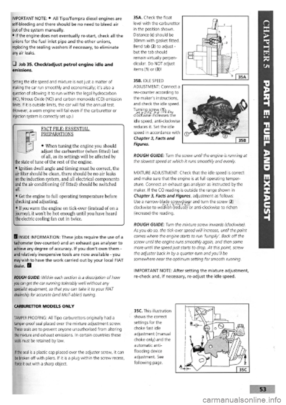
35A. Check the float
level with the carburettor
in the position shown.
Distance (c) should be
30mm with gasket fitted.
Bend tab (2) to adjust
-
but the tab should
remain virtually perpen-
dicular. Do NOT adjust
items (1)or (3)1
35B. IDLE SPEED
ADJUSTMENT: Connect a
rev-counter according to
the maker's instructions,
and check the idle speed.
clockwise increases the
idle speed, anti-clockwise
reduces it. Set the idle
speed in accordance with
Chapter
3,
Facts and
Figures.
ROUGH GUIDE: Turn the screw until the engine is running at
the slowest speed at which it runs smoothly and evenly.
MIXTURE ADJUSTMENT: Check that the idle speed is correct
and make sure that the engine is at full operating temper-
ature. Connect an exhaust gas analyser as instructed by the
maker. If the CO reading is outside the range shown in
Chapter
3,
Facts and Figures, adjustment as follows:
Use a narrow-blade screwdriver and turn the screw (2)
clockwise to weaken (reduce) or anti-clockwise to richen
(increase) the reading.
ROUGH GUIDE: Turn the mixture screw inwards (clockwise).
As you do so, the tick-over speed will increase, until the point
comes where the engine starts to run 'lumpily'. Back off the
screw until the engine runs smoothly again, and then some
more until the speed just starts to drop. At this point, screw
the adjuster back in by a quarter-turn and you'll be
somewhere near the optimum setting for smooth running.
IMPORTANT NOTE: After setting the mixture adjustment,
re-check and, if necessary, re-adjust the idle speed.
CARBURETTOR MODELS ONLY
TAMPER PROOFING: All Tipo carburettors originally had a
tamper-proof seal placed over the mixture adjustment screw.
These
seals are to prevent anyone unauthorised from altering
the
mixture and exhaust emissions. In certain countries these
seals
must be retained by law.
If the
seal
is
a plastic cap placed over the adjuster screw, it can
be
broken
off with pliers. If it is a plug within the screw recess,
force
it out with a sharp object.
35C. This illustration
shows the correct
settings for the
choke fast idle
adjustment (manual
choke only) and the
automatic anti-
flooding device
adjustment. See
following page.
Page 57 of 171
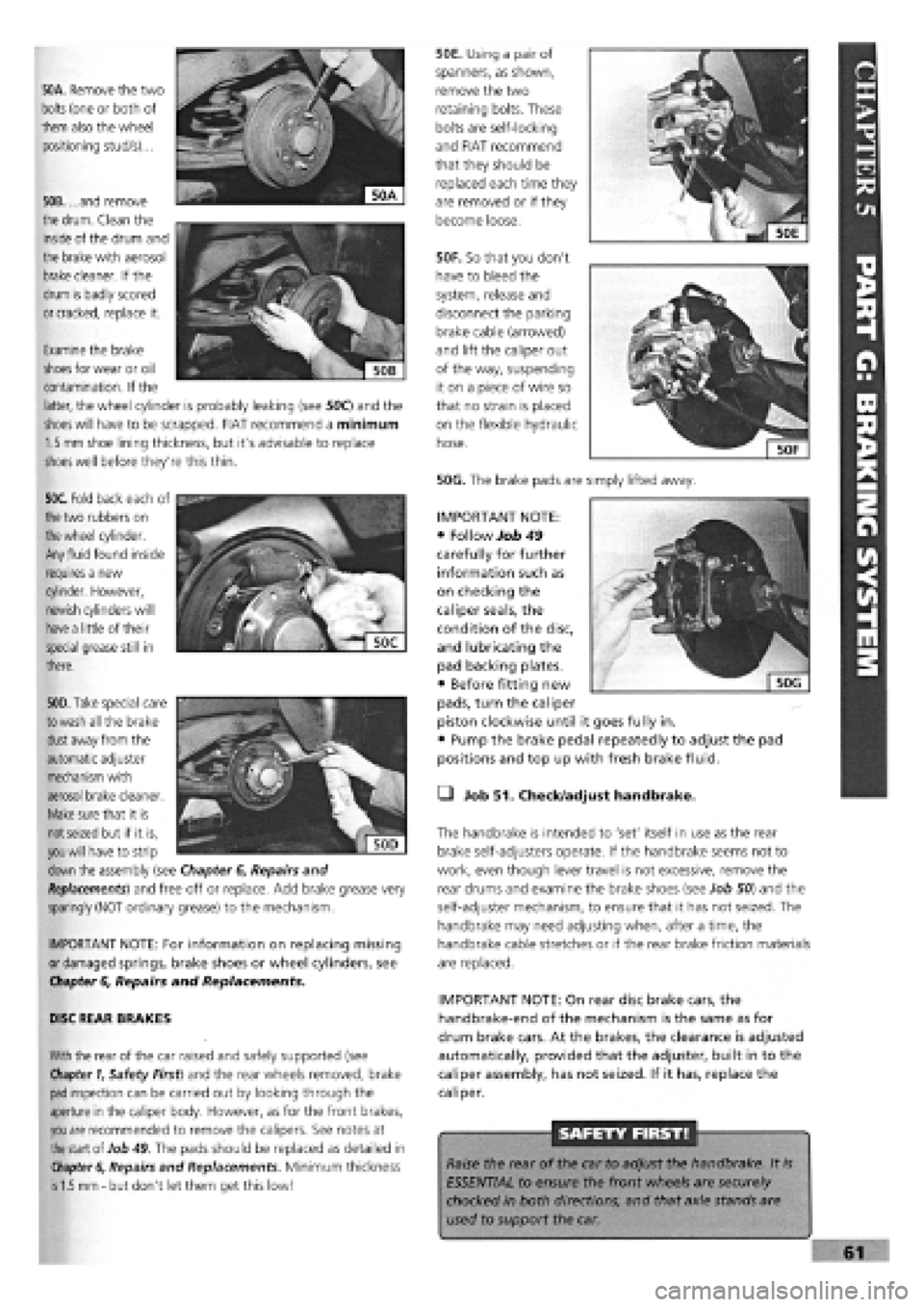
50A. Remove the two
bolts
(one or both of
them also the wheel
positioning stud/s)...
50B. ...and remove
the
drum.
Clean the
inside of the drum and
the brake with aerosol
brake
cleaner. If the
drum is badly scored
or cracked,
replace it.
50F. So that you don't
have to bleed the
system, release and
disconnect the parking
brake cable (arrowed)
and lift the caliper out
of the way, suspending
it on a piece of wire so
that no strain is placed
on the flexible hydraulic
hose.
50G. The brake pads are simply lifted away.
50E. Using a pair of
spanners, as shown,
remove the two
retaining bolts. These
bolts are self-locking
and FIAT recommend
that they should be
replaced each time they
are removed or if they
become loose.
Examine the brake
shoes
for wear or oil
contamination. If the
latter, the wheel cylinder is probably leaking (see 50C) and the
shoes will
have to be scrapped. FIAT recommend a minimum
1.5 mm
shoe lining thickness, but it's advisable to replace
shoes
well before they're this thin.
50C. Fold back each of
the
two rubbers on
the wheel
cylinder.
Any
fluid
found inside
requires a new
cylinder. However,
newish cylinders will
have a
little of their
special grease still in
there.
. """
€
Sjjj
KV,1
| 50D|
50D. Take
special care
to wash
all the brake
dust
away from the
automatic adjuster
mechanism with
aerosol brake cleaner.
Make
sure that it is
not seized
but if it is,
you will
have to strip
down
the assembly (see Chapter
6,
Repairs and
Replacements)
and free off or replace. Add brake grease very
sparingly (NOT ordinary grease) to the mechanism.
IMPORTANT NOTE: For information on replacing missing
or damaged springs, brake shoes or wheel cylinders, see
Chapter
6,
Repairs and Replacements.
DISC REAR BRAKES
With
the rear of the car raised and safely supported (see
Chapter 1,
Safety First) and the rear wheels removed, brake
pad
inspection can be carried out by looking through the
aperture in the caliper body. However, as for the front brakes,
you are
recommended to remove the calipers. See notes at
the
start of Job
49.
The pads should be replaced as detailed in
Chapter 6,
Repairs and Replacements. Minimum thickness
is 1.5 mm -
but don't let them get this low!
• Job 51. Check/adjust handbrake.
The handbrake is intended to 'set' itself in use as the rear
brake self-adjusters operate. If the handbrake seems not to
work, even though lever travel is not excessive, remove the
rear drums and examine the brake shoes (see Job 50) and the
self-adjuster mechanism, to ensure that it has not seized. The
handbrake may need adjusting when, after a time, the
handbrake cable stretches or if the rear brake friction materials
are replaced.
IMPORTANT NOTE: On rear disc brake cars, the
handbrake-end of the mechanism is the same as for
drum brake cars. At the brakes, the clearance is adjusted
automatically, provided that the adjuster, built in to the
caliper assembly, has not seized. If it has, replace the
caliper.
SAFETY FIRST!
Raise the rear of the car to adjust the handbrake. It
is
ESSENTIAL to ensure the front wheels are securely
chocked in both directions, and that axle stands are
used to support the car.
IMPORTANT NOTE:
• Follow Job 49
carefully for further
information such as
on checking the
caliper seals, the
condition of the disc,
and lubricating the
pad backing plates.
• Before fitting new
pads, turn the caliper
piston clockwise until it goes fully in.
• Pump the brake pedal repeatedly to adjust the pad
positions and top up with fresh brake fluid.
Page 61 of 171
PART A: ENGINE
PART A: Contents
Job 1. Petrol engine. Timing belt
-
replacement and Job 12. Petrol engine. Mountings
-
replacement.
adjustment. Job 13. Diesel engine. Timing belt
-
replacement and
Job 2. Petrol engine. Cylinder head
-
removal. adjustment. •
Job 3. Petrol engine. Cylinder head and camshaft housing -Job 14. Diesel engine. Cylinder head
-
removal.
refitting. Job 15. Diesel engine. Cylinder head
-
refitting.
Job
4.
Petrol engine. Cylinder head
-
dismantling and Job 16. Diesel engine. Cylinder head
-
overhaul.
overhauling. Job 17. Diesel engine. Valve clearances
-
adjustment.
Job 5. Petrol engine
-
dismantling. Job 18. Diesel engine
-
removal.
Job
6.
Petrol engine
-
checking and reassembly. Job 19. Diesel engine
-
refitting.
Job
7.
Petrol engine. Valve clearances
-
adjustment. Job 20. Diesel engine. Mountings
-
replacement.
Job 8. Petrol engine/transmission
-
removal. Job 21. Diesel engine/transmission (removed from car)
-
Job
9.
Petrol engine/transmission
-
refitting. separation.
Job 10. Petrol engine/transmission (removed from car)
-
Job 22. Diesel engine/transmission (removed from car)
-
separation. reconnection.
Job 11. Petrol engine/transmission (removed from car)
-
Job 23. Diesel engine
-
dismantling.
reconnection. Job 24. Diesel engine
-
reassembly.
Job 1. Petrol engine. Timing belt
- replacement and adjustment.
Mi*^^ Zc+sc, / • The crankshaft pulley nut
n^^ will be difficult to turn.
• If the engine is in the car,
engage a gear (or 'Park' in the case of an automatic)
and have an assistant hold the footbrake down very
firmly. This will stop the engine from turning.
• Alternatively, with the starter motor removed, you
can have a helper prevent the flywheel ring gear from
turning with a large screwdriver.
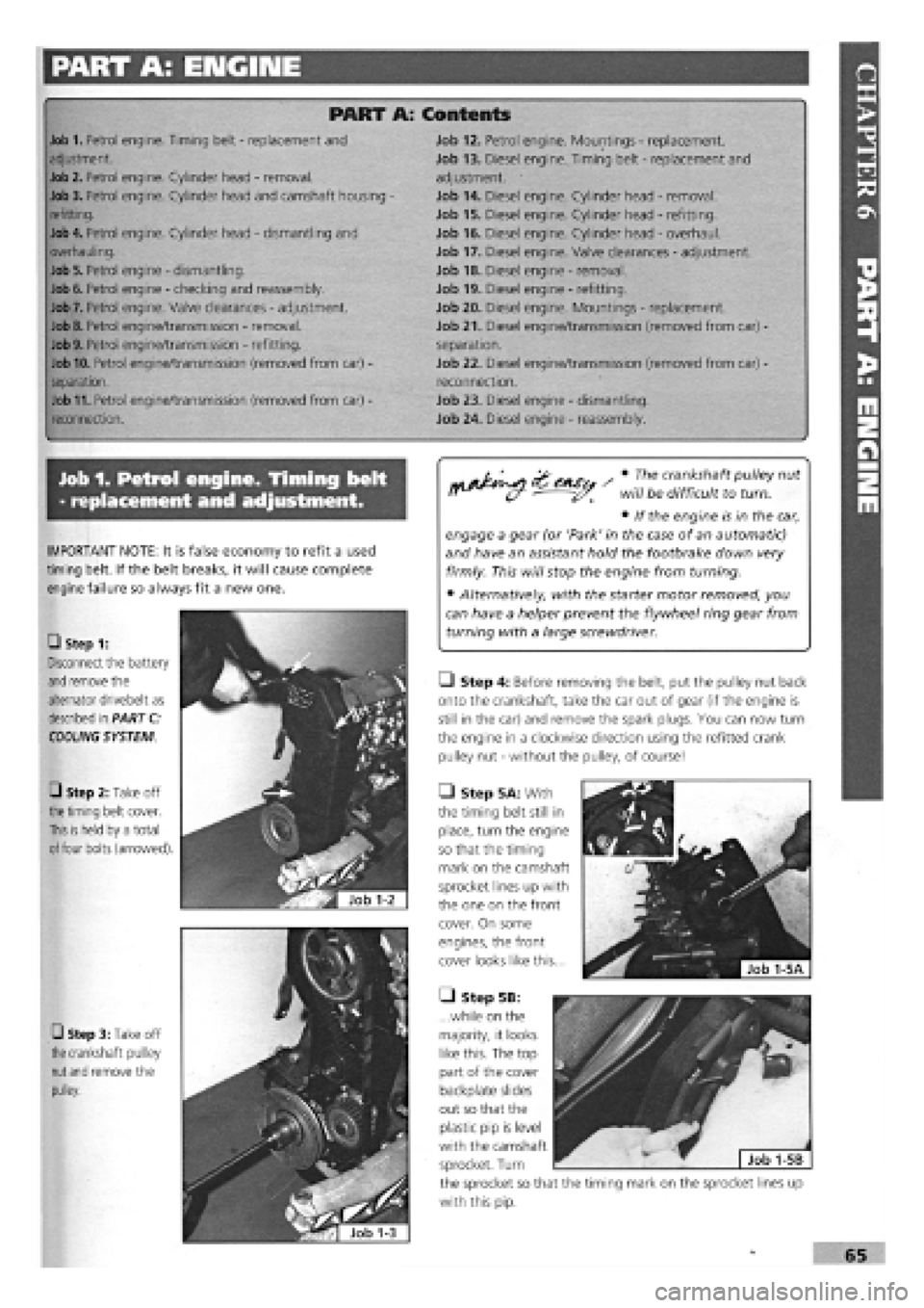
• Step 4: Before removing the belt, put the pulley nut back
onto the crankshaft, take the car out of gear (if the engine is
still in the car) and remove the spark plugs. You can now turn
the engine in a clockwise direction using the refitted crank
pulley nut
-
without the pulley, of course!
• Step 5A: With
the timing belt still in
place, turn the engine
so that the timing
mark on the camshaft
sprocket lines up with
the one on the front
cover. On some
engines, the front
cover looks like this...
• Step 5B:
...while on the
majority, it looks
like this. The top
part of the cover
backplate slides
out so that the
plastic pip is level
with the camshaft
sprocket. Turn
the sprocket so that the timing mark on the sprocket lines up
with this pip.
IMPORTANT NOTE: It is false economy to refit a used
timing belt. If the belt breaks, it will cause complete
engine failure so always fit a new one.
• Step 1:
Disconnect the battery
and
remove the
alternator drivebelt as
described in PART C:
COOLING
SYSTEM
0 Step 2: Take off
the timing
belt cover.
This is held
by a total
of
four bolts (arrowed).
• Step 3: Take off
the
crankshaft pulley
nut and
remove the
pulley.