FIAT ULYSSE 2008 2.G Owner's Manual
Manufacturer: FIAT, Model Year: 2008, Model line: ULYSSE, Model: FIAT ULYSSE 2008 2.GPages: 254, PDF Size: 3.46 MB
Page 21 of 254
GETTING TO KNOW YOUR CAR
20
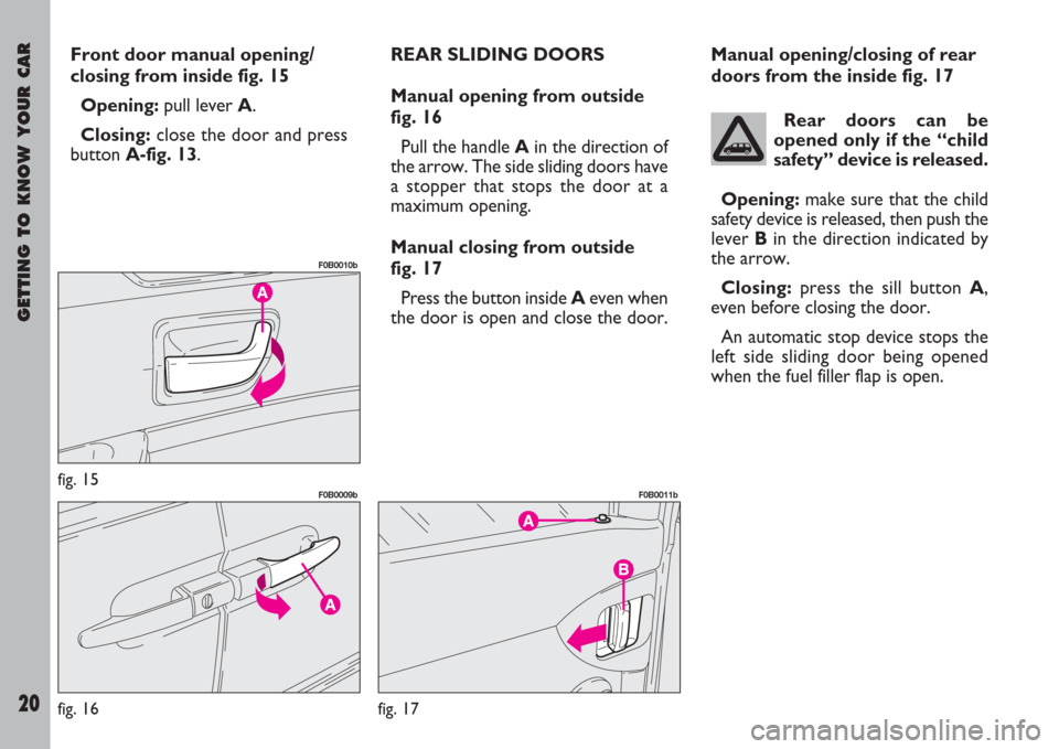
Front door manual opening/
closing from inside fig. 15
Opening:pull lever A.
Closing:close the door and press
buttonA-fig. 13.REAR SLIDING DOORS
Manual opening from outside
fig. 16
Pull the handle Ain the direction of
the arrow. The side sliding doors have
a stopper that stops the door at a
maximum opening.
Manual closing from outside
fig. 17
Press the button inside Aeven when
the door is open and close the door.Manual opening/closing of rear
doors from the inside fig. 17
Rear doors can be
opened only if the “child
safety” device is released.
Opening:make sure that the child
safety device is released, then push the
lever Bin the direction indicated by
the arrow.
Closing:press the sill button A,
even before closing the door.
An automatic stop device stops the
left side sliding door being opened
when the fuel filler flap is open.
fig. 15
F0B0010b
fig. 16
F0B0009b
fig. 17
F0B0011b
Page 22 of 254
GETTING TO KNOW YOUR CAR
21
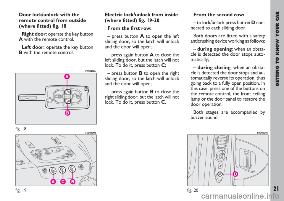
Door lock/unlock with the
remote control from outside
(where fitted) fig. 18
Right door:operate the key button
A with the remote control.
Left door:operate the key button
Bwith the remote control.Electric lock/unlock from inside
(where fitted) fig. 19-20
From the first row:
– press button A to open the left
sliding door, so the latch will unlock
and the door will open;
– press again button A to close the
left sliding door, but the latch will not
lock. To do it, press button C;
– press button Bto open the right
sliding door, so the latch will unlock
and the door will open;
– press again button Bto close the
right sliding door, but the latch will not
lock. To do it, press button C.From the second row:
– to lock/unlock press button Dcon-
nected to each sliding door.
Both doors are fitted with a safety
anticrushing device working as follows:
– during opening: when an obsta-
cle is detected the door stops auto-
matically;
– during closing: when an obsta-
cle is detected the door stops and au-
tomatically reverse its operation, thus
going back to a fully open position. In
this case, press one of the buttons on
the remote control, the front ceiling
lamp or the door panel to restore the
door operation.
Both stages are accompanied by
buzzer sound
fig. 18
F0B0408b
fig. 19
F0B0409b
fig. 20
F0B0221b
Page 23 of 254
GETTING TO KNOW YOUR CAR
22
CENTRAL DOOR LOCKING
SYSTEM
From the outside
With the doors closed: insert and
turn the key in the lock of one of the
front doors.
From the inside
With the doors closed: press button
C-fig. 19placed next to the front ceil-
ing lamp.
Pressing or lifting one of the rear sill
buttons only locks or unlocks the par-
ticular door involved.
IMPORTANTIf one of the doors
is not shut properly or there is a fail-
ure in the system, the central locking
feature will not work and the direc-
tion indicators will not flash; after
some attempts, the device stops
working for around 20 seconds. In
these 20 seconds, the door can be
locked or unlocked manually without
the electrical system coming into play.
After the 20-second period, the con-
trol unit is ready to receive commands
once more.
If the reason for the malfunction has
been removed, the device will start to
work properly again. If not, it will cut
out once more.“Door open” alarm
If, with engine running, one of the
doors is not shut properly, the multi-
function display will show a dedicat-
ed message and the buzzer will sound.
SUPER DOOR LOCK
(where fitted)
To engage the super door lock using
the remote control, press button A-
fig. 8once and then press it again
within 5 seconds. After the first click
they will click again to signal that they
have been engaged.
To activate the super door lock with
the key, place it in the lock and hold
it in the locking position for a few sec-
onds until you hear the second click
indicating that the doors have been
locked.
This operation is necessary if you do
not wish to engage the electronic
alarm.When the super door
lock has been activated it
is impossible to open the
doors even from the inside; for
this reason do not use the super
door lock when there are pas-
sengers in the vehicle.
The super door lock is deactivated
when the doors are unlocked with a
key or remote control by pressing the
pushbutton B-fig. 8.
Page 24 of 254
GETTING TO KNOW YOUR CAR
23
CHILD SAFETY LOCK
There can be 2 types of “Children
safety”: electric safety or mechanical
safety.
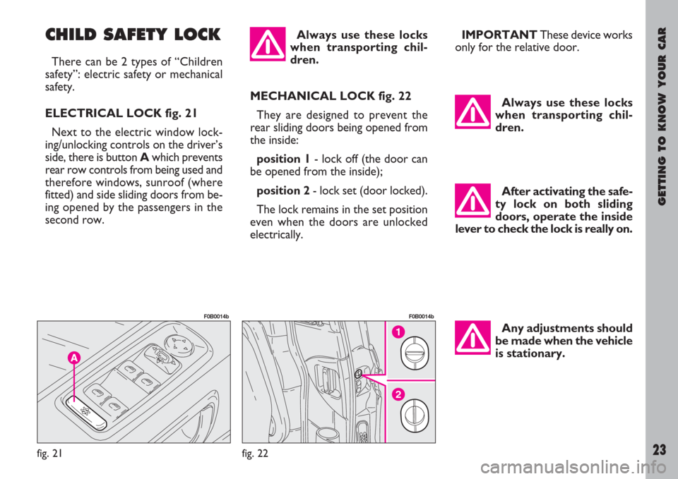
ELECTRICAL LOCK fig. 21
Next to the electric window lock-
ing/unlocking controls on the driver’s
side, there is button Awhich prevents
rear row controls from being used and
therefore windows, sunroof (where
fitted) and side sliding doors from be-
ing opened by the passengers in the
second row.
Any adjustments should
be made when the vehicle
is stationary.Always use these locks
when transporting chil-
dren.
2
1
fig. 22
F0B0014b
fig. 21
F0B0014b
MECHANICAL LOCK fig. 22
They are designed to prevent the
rear sliding doors being opened from
the inside:
position 1- lock off (the door can
be opened from the inside);
position 2- lock set (door locked).
The lock remains in the set position
even when the doors are unlocked
electrically.After activating the safe-
ty lock on both sliding
doors, operate the inside
lever to check the lock is really on. Always use these locks
when transporting chil-
dren.
IMPORTANTThese device works
only for the relative door.
Page 25 of 254
GETTING TO KNOW YOUR CAR
24
Once you have released
the lever, check that the
seat is firmly locked in the
runners by trying to move it back
and forth. Failure to lock the seat
in place could result in the seat
moving suddenly and the driver
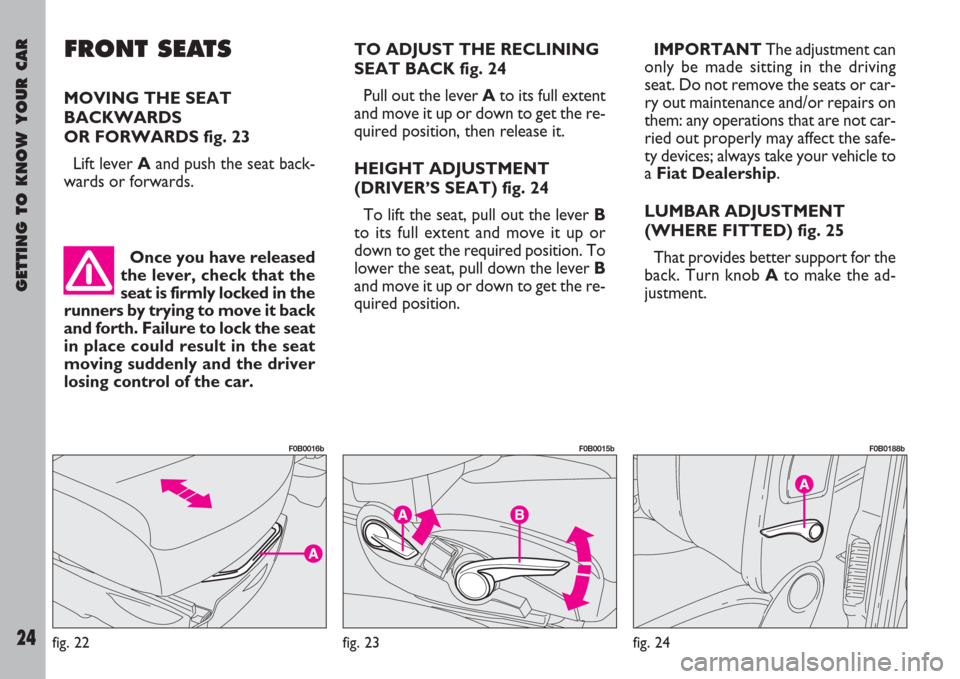
losing control of the car.TO ADJUST THE RECLINING
SEAT BACK fig. 24
Pull out the lever Ato its full extent
and move it up or down to get the re-
quired position, then release it.
HEIGHT ADJUSTMENT
(DRIVER’S SEAT) fig. 24
To lift the seat, pull out the lever B
to its full extent and move it up or
down to get the required position. To
lower the seat, pull down the lever B
and move it up or down to get the re-
quired position.IMPORTANTThe adjustment can
only be made sitting in the driving
seat. Do not remove the seats or car-
ry out maintenance and/or repairs on
them: any operations that are not car-
ried out properly may affect the safe-
ty devices; always take your vehicle to
a Fiat Dealership.
LUMBAR ADJUSTMENT
(WHERE FITTED) fig. 25
That provides better support for the
back. Turn knob Ato make the ad-
justment.
FRONT SEATS
MOVING THE SEAT
BACKWARDS
OR FORWARDS fig. 23
Lift lever Aand push the seat back-
wards or forwards.
fig. 23
F0B0015b
fig. 24
F0B0188b
fig. 22
F0B0016b
Page 26 of 254
GETTING TO KNOW YOUR CAR
25
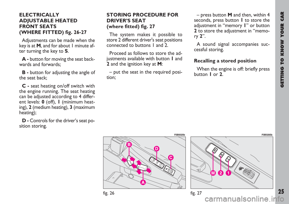
ELECTRICALLY
ADJUSTABLE HEATED
FRONT SEATS
(WHERE FITTED) fig. 26-27
Adjustments can be made when the
key is at M, and for about 1 minute af-
ter turning the key to S.
A -button for moving the seat back-
wards and forwards;
B -button for adjusting the angle of
the seat back;
C -seat heating on/off switch with
the engine running. The seat heating
can be adjusted according to 4 differ-
ent levels: 0(off), 1(minimum heat-
ing), 2(medium heating), 3(maximum
heating);
D -Controls for the driver’s seat po-
sition storing. STORING PROCEDURE FOR
DRIVER’S SEAT
(where fitted) fig. 27
The system makes it possible to
store 2 different driver's seat positions
connected to buttons 1 and 2.
Proceed as follows to store the ad-
justments available with button 1and
2and the ignition key at M:
– put the seat in the required posi-
tion;– press button Mand then, within 4
seconds, press button 1to store the
adjustment in “memory 1” or button
2to store the adjustment in “memo-
ry 2”.
A sound signal accompanies suc-
cessful storing.
Recalling a stored position
When the engine is off: briefly press
button 1or 2.
fig. 26
F0B0020b
fig. 27
F0B0285b
Page 27 of 254
GETTING TO KNOW YOUR CAR
26
IMPORTANTAfter 5 unsuccess-
ful recalls, the system locks the rela-
tive control which will be restored
when the engine is started.
When the engine is on: press and
keep button 1or 2pressed until the
stored position is reached.
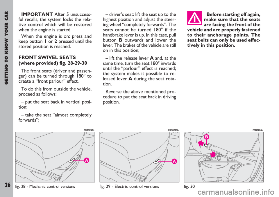
FRONT SWIVEL SEATS
(where provided) fig. 28-29-30
The front seats (driver and passen-
ger) can be turned through 180° to
create a “front parlour” effect.
To do this from outside the vehicle,
proceed as follows:
– put the seat back in vertical posi-
tion;
– take the seat “almost completely
forwards”;– driver’s seat: lift the seat up to the
highest position and adjust the steer-
ing wheel “completely forwards”. The
seats cannot be turned 180° if the
handbrake lever is up. In this case, pull
button Boutwards and lower the
lever. The brakes of the vehicle are still
on in this position;
– lift the release lever Aand, at the
same time, turn the seat 180° inwards
until the “parlour” effect is reached;
the system makes it possible to re-
leased lever Aduring the seat rota-
tion.
Reverse the above mentioned pro-
cedure to put the seat back in driving
position.Before starting off again,
make sure that the seats
are facing the front of the
vehicle and are properly fastened
to their anchorage points. The
seat belts can only be used effec-
tively in this position.
fig. 29 - Electric control versions
F0B0223b
fig. 28 - Mechanic control versions
F0B0290b
fig. 30
F0B0224b
Page 28 of 254
GETTING TO KNOW YOUR CAR
27
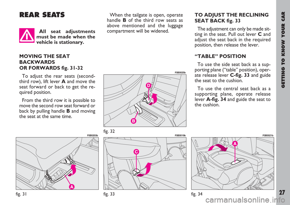
REAR SEATSWhen the tailgate is open, operate
handle Bof the third row seats as
above mentioned and the luggage
compartment will be widened.TO ADJUST THE RECLINING
SEAT BACK fig. 33
The adjustment can only be made sit-
ting in the seat. Pull out lever Cand
adjust the seat back in the required
position, then release the lever.
“TABLE” POSITION
To use the side seat back as a sup-
porting plane (“table” position), oper-
ate release lever C-fig. 33and guide
the seat to the cushion.
To use the central seat back as a
supporting plane, operate release
lever A-fig. 34and guide the seat to
the cushion.
fig. 31
F0B0203bfig. 32
F0B0025b
fig. 33
F0B0019b
All seat adjustments
must be made when the
vehicle is stationary.
MOVING THE SEAT
BACKWARDS
OR FORWARDS fig. 31-32
To adjust the rear seats (second-
third row), lift lever Aand move the
seat forward or back to get the re-
quired position.
From the third row it is possible to
move the second row seat forward or
back by pulling handle Band moving
the seat at the same time.
fig. 34
F0B0021b
Page 29 of 254
GETTING TO KNOW YOUR CAR
28
To put the seat back into vertical po-
sition, push it upwards until it clicks
and locks in that position.
“WALLET” POSITION
Side seats
Operate release lever C-fig. 33and
guide the seat back until the “table”
position is reached; then turn the
tipped seat again until the “wallet” po-
sition illustrated in fig. 36 is reached.
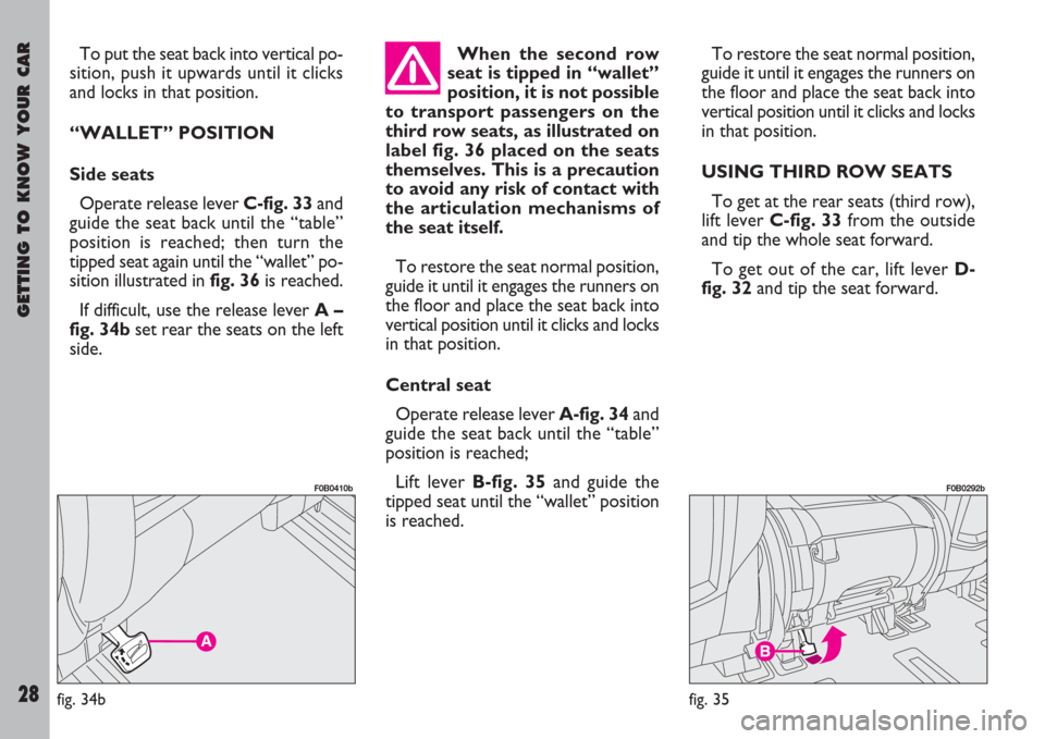
If difficult, use the release lever A –
fig. 34bset rear the seats on the left
side.To restore the seat normal position,
guide it until it engages the runners on
the floor and place the seat back into
vertical position until it clicks and locks
in that position.
USING THIRD ROW SEATS
To get at the rear seats (third row),
lift lever C-fig. 33from the outside
and tip the whole seat forward.
To get out of the car, lift lever D-
fig. 32and tip the seat forward. When the second row
seat is tipped in “wallet”
position, it is not possible
to transport passengers on the
third row seats, as illustrated on
label fig. 36 placed on the seats
themselves. This is a precaution
to avoid any risk of contact with
the articulation mechanisms of
the seat itself.
To restore the seat normal position,
guide it until it engages the runners on
the floor and place the seat back into
vertical position until it clicks and locks
in that position.
Central seat
Operate release lever A-fig. 34and
guide the seat back until the “table”
position is reached;
Lift lever B-fig. 35and guide the
tipped seat until the “wallet” position
is reached.
fig. 35
F0B0292b
fig. 34b
F0B0410b
Page 30 of 254
GETTING TO KNOW YOUR CAR
29
DISMANTLING THE SECOND
AND THIRD ROW SEATS
To dismantle:
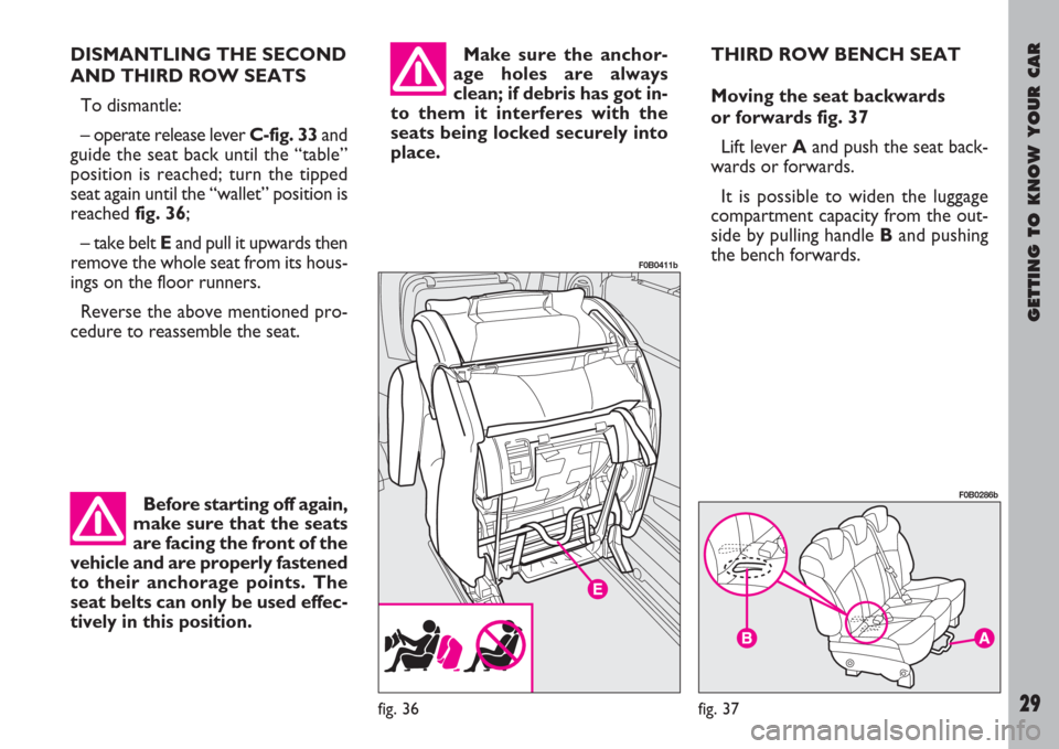
– operate release lever C-fig. 33and
guide the seat back until the “table”
position is reached; turn the tipped
seat again until the “wallet” position is
reached fig. 36;
– take belt Eand pull it upwards then
remove the whole seat from its hous-
ings on the floor runners.
Reverse the above mentioned pro-
cedure to reassemble the seat.Make sure the anchor-
age holes are always
clean; if debris has got in-
to them it interferes with the
seats being locked securely into
place.THIRD ROW BENCH SEAT
Moving the seat backwards
or forwards fig. 37
Lift lever Aand push the seat back-
wards or forwards.
It is possible to widen the luggage
compartment capacity from the out-
side by pulling handle Band pushing
the bench forwards.
fig. 36
F0B0411b
Before starting off again,
make sure that the seats
are facing the front of the
vehicle and are properly fastened
to their anchorage points. The
seat belts can only be used effec-
tively in this position.
fig. 37
F0B0286b