FIAT UNO 1983 Service Manual PDF
Manufacturer: FIAT, Model Year: 1983, Model line: UNO, Model: FIAT UNO 1983Pages: 303, PDF Size: 10.36 MB
Page 71 of 303
6On 1116 cc and 1301 cc models, the
exhaust system is of dual downpipe, two
silencer, two section type.
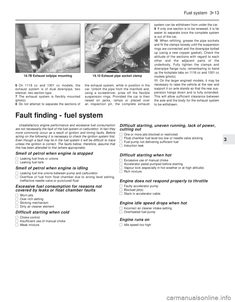
7The exhaust system is flexibly mounted
(photo).
8Do not attempt to separate the sections ofthe exhaust system, while in position in the
car. Unbolt the pipe from the manifold and,
using a screwdriver, prise off the flexible
suspension rings. Provided the car is then
raised on jacks, ramps or placed over
an inspection pit, the complete exhaust system can be withdrawn from under the car.
9If only one section is to be renewed, it is far
easier to separate once the complete system
is out of the car.
10When refitting, grease the pipe sockets
and fit the clamps loosely until the suspension
rings are connected and the downpipe bolted
up (using a new copper gasket). Check the
attitude of the sections with regard to each
other and the adjacent parts of the
underbody. Fully tighten the clamps and
downpipe flange nuts, remembering to bend
up the lockplate tabs on 1116 cc and 1301 cc
models (photo).
11On the larger engined models, it may be
necessary to raise the vehicle at the rear and
support it on axle stands so that the rear sus-
pension hangs down and is fully extended.
This will allow sufficient clearance between
the axle and the body for the exhaust system
to be withdrawn.
Fuel system 3•13
3
19.10 Exhaust pipe socket clamp19.7B Exhaust tailpipe mounting
Fault finding - fuel system
Unsatisfactory engine performance and excessive fuel consumption
are not necessarily the fault of the fuel system or carburettor. In fact they
more commonly occur as a result of ignition and timing faults. Before
acting on the following it is necessary to check the ignition system first.
Even though a fault may lie in the fuel system it will be difficult to trace
unless the ignition is correct. The faults below, therefore, assume that
this has been attended to first (where appropriate).
Smell of petrol when engine is stopped
m mLeaking fuel lines or unions
m mLeaking fuel tank
Smell of petrol when engine is idling
m
mLeaking fuel line unions between pump and carburettor
m mOverflow of fuel from float chamber due to wrong level setting,
ineffective needle valve or punctured float
Excessive fuel consumption for reasons not
covered by leaks or float chamber faults
m mWorn jets
m mOver-rich setting
m mSticking mechanism
m mDirty air cleaner element
Difficult starting when cold
m
mChoke control
m mInsufficient use of manual choke
m mWeak mixture
Difficult starting, uneven running, lack of power,
cutting out
m mOne or more jets blocked or restricted
m mFloat chamber fuel level too low or needle valve sticking
m mFuel pump not delivering sufficient fuel
m mInduction leak
Difficult starting when hot
m
mExcessive use of manual choke
m mAccelerator pedal pumped before starting
m mVapour lock (especially in hot weather or at high altitude)
m mRich mixture
Engine does not respond properly to throttle
m
mFaulty accelerator pump
m mBlocked jet(s)
m mSlack in accelerator cable
Engine idle speed drops when hot
m
mIncorrect air cleaner intake setting
m mOverheated fuel pump
Engine runs on
m
mIdle speed too high
Page 72 of 303
4
System type
Except ES engines . . . . . . . . . . . . . . . . . . . . . . . . . . . . . . . . . . . . . . . . . Battery, coil mechanical breaker distributor
ES engines . . . . . . . . . . . . . . . . . . . . . . . . . . . . . . . . . . . . . . . . . . . . . . . Marelli Digiplex electronic with breakerless distributor
Firing order . . . . . . . . . . . . . . . . . . . . . . . . . . . . . . . . . . . . . . . . . . . . 1 - 3 - 4 - 2 (No. 1 cylinder at crankshaft pulley end)
Mechanical breaker distributor
Type . . . . . . . . . . . . . . . . . . . . . . . . . . . . . . . . . . . . . . . . . . . . . . . . . . . . Marelli or Ducellier
Contact breaker points gap . . . . . . . . . . . . . . . . . . . . . . . . . . . . . . . . . . 0.37 to 0.43 mm (0.015 to 0.017 in)
Condenser capacity . . . . . . . . . . . . . . . . . . . . . . . . . . . . . . . . . . . . . . . . 0.20 to 0.25 µF
Dwell angle . . . . . . . . . . . . . . . . . . . . . . . . . . . . . . . . . . . . . . . . . . . . . . . 52 to 58º
Rotor rotational direction . . . . . . . . . . . . . . . . . . . . . . . . . . . . . . . . . . . . Clockwise
Ignition timing (dynamic)
903 cc engine . . . . . . . . . . . . . . . . . . . . . . . . . . . . . . . . . . . . . . . . . . . 5º BTDC at idle
1116 and 1301 cc engines . . . . . . . . . . . . . . . . . . . . . . . . . . . . . . . . . 10º BTDC at idle
Centrifugal advance:
903 cc engine . . . . . . . . . . . . . . . . . . . . . . . . . . . . . . . . . . . . . . . . . . . Between 30 and 34º max
1116 and 1301 cc engines . . . . . . . . . . . . . . . . . . . . . . . . . . . . . . . . . Between 22 and 24º max
Vacuum advance . . . . . . . . . . . . . . . . . . . . . . . . . . . . . . . . . . . . . . . . . . Between 10 and 14º max
Ignition coil
Primary winding resistance at 20ºC (68ºF) . . . . . . . . . . . . . . . . . . . . . . . Between 2.6 and 3.3 ohms depending upon make of coil
Secondary winding resistance at 20ºC (68ºF) . . . . . . . . . . . . . . . . . . . . Between 6745 and 12 000 ohms depending upon make of coil
Marelli Digiplex electronic ignition
Rotor arm resistance . . . . . . . . . . . . . . . . . . . . . . . . . . . . . . . . . . . . . . . 1000 ohms
Advance range . . . . . . . . . . . . . . . . . . . . . . . . . . . . . . . . . . . . . . . . . . . . Between 6 to 10º and 47 to 51º
Engine speed sensor
Resistance on flywheel . . . . . . . . . . . . . . . . . . . . . . . . . . . . . . . . . . . . . . 612 to 748 ohms
Sensor to flywheel tooth gap . . . . . . . . . . . . . . . . . . . . . . . . . . . . . . . . . 0.25 to 1.3 mm (0.0099 to 0.0512 in)
TDC sensor
Resistance on pulley . . . . . . . . . . . . . . . . . . . . . . . . . . . . . . . . . . . . . . . . 612 to 748 ohms
Sensor to pulley tooth gap . . . . . . . . . . . . . . . . . . . . . . . . . . . . . . . . . . . 0.4 to 1.0 mm (0.016 to 0.039 in)
Ignition coil
Primary winding resistance at 20ºC (68ºF) . . . . . . . . . . . . . . . . . . . . . . . 0.310 to 0.378 ohms
Secondary winding resistance at 20ºC (68ºF) . . . . . . . . . . . . . . . . . . . . 3330 to 4070 ohms
Chapter 4 Ignition system
For modifications and information applicable to later models, see Supplement at end of manual
Condenser (capacitor) - removal, testing and refitting . . . . . . . . . . . 5
Digiplex (electronic) - ignition checks and adjustments . . . . . . . . . . 10
Digiplex (electronic) ignition - location of components and
precautions . . . . . . . . . . . . . . . . . . . . . . . . . . . . . . . . . . . . . . . . . . 9
Distributor - removal and refitting . . . . . . . . . . . . . . . . . . . . . . . . . . . 6
Distributor (mechanical breaker type) - overhaul . . . . . . . . . . . . . . . 7
Dwell angle - checking . . . . . . . . . . . . . . . . . . . . . . . . . . . . . . . . . . . 3Fault finding - ignition system . . . . . . . . . . . . . . . . See end of Chapter
General description . . . . . . . . . . . . . . . . . . . . . . . . . . . . . . . . . . . . . . 1
Ignition coil - (mechanical breaker ignition) . . . . . . . . . . . . . . . . . . . . 8
Ignition switch - removal and refitting . . . . . . . . . . . . . . . . . . . . . . . . 12
Ignition timing . . . . . . . . . . . . . . . . . . . . . . . . . . . . . . . . . . . . . . . . . . 4
Mechanical contact breaker - points servicing . . . . . . . . . . . . . . . . . 2
Spark plugs . . . . . . . . . . . . . . . . . . . . . . . . . . . . . . . . . . . . . . . . . . . . 11
4•1
Specifications Contents
Easy,suitable for
novice with little
experienceFairly easy,suitable
for beginner with
some experienceFairly difficult,
suitable for competent
DIY mechanic
Difficult,suitable for
experienced DIY
mechanicVery difficult,
suitable for expert DIY
or professional
Degrees of difficulty
54321
Page 73 of 303
Spark plugs
Type . . . . . . . . . . . . . . . . . . . . . . . . . . . . . . . . . . . . . . . . . . . . . . . . . . . . Champion RN9YCC or RN9YC
Electrode gap . . . . . . . . . . . . . . . . . . . . . . . . . . . . . . . . . . . . . . . . . . . . . 0.8 mm (0.031 in)
HT leads
903 cc (45) . . . . . . . . . . . . . . . . . . . . . . . . . . . . . . . . . . . . . . . . . . . . . . . Champion LS-07
1116, 1299 and 1301 cc (55, 60 and 70) . . . . . . . . . . . . . . . . . . . . . . . . Champion LS-05
Torque wrench settingNm lbf ft
Spark plugs . . . . . . . . . . . . . . . . . . . . . . . . . . . . . . . . . . . . . . . . . . . . . . . 25 18
4•2 Ignition system
1 General description
On all models except the 903 ES engine
version, a mechanical contact breaker type
distributor is fitted.
On 45 Super ES models which have the
903 ES engine, an electronic (Digiplex) ignition
system is used which incorporates a
breakerless distributor.
Mechanical contact breaker
system
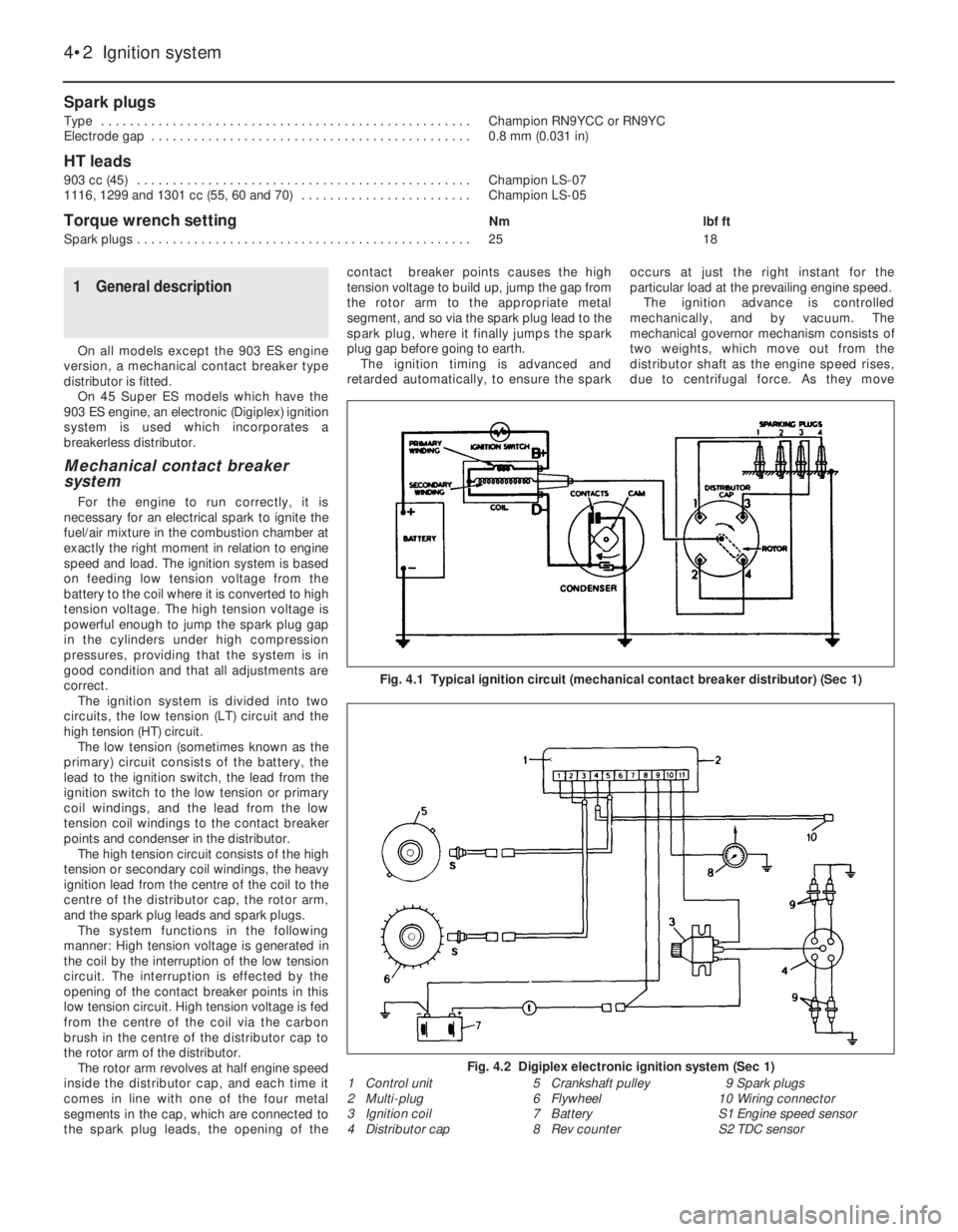
For the engine to run correctly, it is
necessary for an electrical spark to ignite the
fuel/air mixture in the combustion chamber at
exactly the right moment in relation to engine
speed and load. The ignition system is based
on feeding low tension voltage from the
battery to the coil where it is converted to high
tension voltage. The high tension voltage is
powerful enough to jump the spark plug gap
in the cylinders under high compression
pressures, providing that the system is in
good condition and that all adjustments are
correct.
The ignition system is divided into two
circuits, the low tension (LT) circuit and the
high tension (HT) circuit.
The low tension (sometimes known as the
primary) circuit consists of the battery, the
lead to the ignition switch, the lead from the
ignition switch to the low tension or primary
coil windings, and the lead from the low
tension coil windings to the contact breaker
points and condenser in the distributor.
The high tension circuit consists of the high
tension or secondary coil windings, the heavy
ignition lead from the centre of the coil to the
centre of the distributor cap, the rotor arm,
and the spark plug leads and spark plugs.
The system functions in the following
manner: High tension voltage is generated in
the coil by the interruption of the low tension
circuit. The interruption is effected by the
opening of the contact breaker points in this
low tension circuit. High tension voltage is fed
from the centre of the coil via the carbon
brush in the centre of the distributor cap to
the rotor arm of the distributor.
The rotor arm revolves at half engine speed
inside the distributor cap, and each time it
comes in line with one of the four metal
segments in the cap, which are connected to
the spark plug leads, the opening of thecontact breaker points causes the high
tension voltage to build up, jump the gap from
the rotor arm to the appropriate metal
segment, and so via the spark plug lead to the
spark plug, where it finally jumps the spark
plug gap before going to earth.
The ignition timing is advanced and
retarded automatically, to ensure the sparkoccurs at just the right instant for the
particular load at the prevailing engine speed.
The ignition advance is controlled
mechanically, and by vacuum. The
mechanical governor mechanism consists of
two weights, which move out from the
distributor shaft as the engine speed rises,
due to centrifugal force. As they move
Fig. 4.1 Typical ignition circuit (mechanical contact breaker distributor) (Sec 1)
1 Control unit
2 Multi-plug
3 Ignition coil
4 Distributor cap5 Crankshaft pulley
6 Flywheel
7 Battery
8 Rev counter9 Spark plugs
10 Wiring connector
S1 Engine speed sensor
S2 TDC sensor
Fig. 4.2 Digiplex electronic ignition system (Sec 1)
Page 74 of 303
outwards, they rotate the cam relative to the
distributor shaft, and so advance the spark.
The weights are held in position by two
springs and it is the tension of the springs
which is largely responsible for correct spark
advancement.
The vacuum advance is controlled by a
diaphragm capsule connected to the
carburettor venturi. The vacuum pressure
varies according to the throttle valve plate
opening and so adjusts the ignition advance
in accordance with the engine requirements.
Digiplex ignition system
This electronic system eliminates the
mechanical contact breaker and centrifugal
advance mechanism of conventional
distributors and uses an electronic control
unit to provide advance values according to
engine speed and load. No provision is made
for adjustment of the ignition timing.
Information relayed to the control unit is
provided by two magnetic sensors which
monitor engine speed and TDC directly from
the engine crankshaft.
A vacuum sensor in the control unit
converts intake manifold vacuum into an
electric signal.
The control unit selects the optimum
advance angle required and a closed
magnetic circuit resin coil guarantees a spark
owing to the low primary winding resistance.
Five hundred and twelve advance values
are stored in the control unit memory to suit
any combination of engine operating
conditions.
No maintenance is required to the
distributor used on this system.
Distributor drive
The mechanical breaker type distributor on
903 cc engines and the Digiplex type
distributor on 903 cc ES engines are mounted
on the cylinder head and driven from a gear
on the camshaft through a shaft which also
drives the oil pump.
The distributor on 1116 cc and 1301 cc
engines is mounted on the crankcase and is
driven from a gear on the auxiliary shaft as is
also the oil pump.
2 Mechanical contact breaker
- points servicing
3
1At the intervals specified in “Routine
Maintenance”, prise down the clips on the
distributor cap and place the cap with high
tension leads to one side.
2Pull off the rotor.
3Remove the spark shield. Mechanical wear
of the contact breaker reduces the gap.
Electrical wear builds up a “pip” of burned
metal on one of the contacts. This
|prevents the gap being measured for
re-adjustment, and also spoils the electric
circuit.
Ducellier type distributor
4To remove the contact breaker movable
arm, extract the clip and take off the washer
from the top of the pivot post.
5Extract the screw and remove the fixed
contact arm.
6Clean the points by rubbing the surfaces on
a fine abrasive such as an oil stone. The point
surface should be shaped to a gentle convex
curve. All the “pip” burned onto one contact
must be removed. It is not necessary to go on
until all traces of the crater have been
removed from the other. There is enough
metal on the contacts to allow this to be done
once. At alternate services, fit new points.
Wash debris off cleaned points and
preservatives off new ones.
7Now the distributor should be lubricated.
This lubrication is important for the correct
mechanical function of the distributor, but
excess lubrication will ruin the electrical
circuits, and give difficult starting.
8Whilst the contact breaker is off, squirt
some engine oil into the bottom part of the
distributor, onto the centrifugal advance
mechanism below the plate.
9Wet with oil the felt pad on the top of the
distributor spindle, normally covered by the
rotor arm.
10Put just a drip of oil on the pivot for the
moving contact.11Smear a little general purpose grease
onto the cam, and the heel of the moving
contact breaker.
12Refit the contact points and then set the
gap in the following way.
13Turn the crankshaft by applying a spanner
to the pulley nut or by jacking up a front
wheel, engaging top gear and turning the
roadwheel in the forward direction of
travel. Keep turning until the plastic
heel of the movable contact arm is on the
high point of a cam lobe on the distributor
shaft.
14Set the points gap by moving the fixed
contact arm until the specified feeler blades
are a sliding fit. Tighten the fixed contact arm
screw.
15Check the contact end of the rotor arm.
Remove any slightly burnt deposits using fine
abrasive paper. Severe erosion will
necessitate renewal of the rotor.
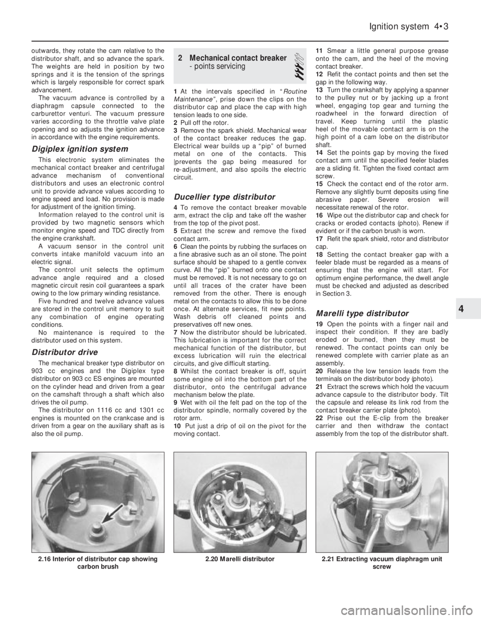
16Wipe out the distributor cap and check for
cracks or eroded contacts (photo). Renew if
evident or if the carbon brush is worn.
17Refit the spark shield, rotor and distributor
cap.
18Setting the contact breaker gap with a
feeler blade must be regarded as a means of
ensuring that the engine will start. For
optimum engine performance, the dwell angle
must be checked and adjusted as described
in Section 3.
Marelli type distributor
19Open the points with a finger nail and
inspect their condition. If they are badly
eroded or burned, then they must be
renewed. The contact points can only be
renewed complete with carrier plate as an
assembly.
20Release the low tension leads from the
terminals on the distributor body (photo).
21Extract the screws which hold the vacuum
advance capsule to the distributor body. Tilt
the capsule and release its link rod from the
contact breaker carrier plate (photo).
22Prise out the E-clip from the breaker
carrier and then withdraw the contact
assembly from the top of the distributor shaft.
Ignition system 4•3
2.21 Extracting vacuum diaphragm unit
screw2.20 Marelli distributor2.16 Interior of distributor cap showing
carbon brush
4
Page 75 of 303
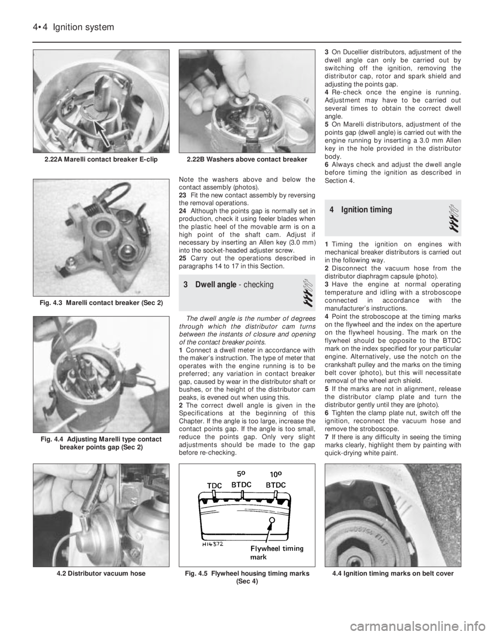
Note the washers above and below the
contact assembly (photos).
23Fit the new contact assembly by reversing
the removal operations.
24Although the points gap is normally set in
production, check it using feeler blades when
the plastic heel of the movable arm is on a
high point of the shaft cam. Adjust if
necessary by inserting an Allen key (3.0 mm)
into the socket-headed adjuster screw.
25Carry out the operations described in
paragraphs 14 to 17 in this Section.
3 Dwell angle- checking
3
The dwell angle is the number of degrees
through which the distributor cam turns
between the instants of closure and opening
of the contact breaker points.
1Connect a dwell meter in accordance with
the maker’s instruction. The type of meter that
operates with the engine running is to be
preferred; any variation in contact breaker
gap, caused by wear in the distributor shaft or
bushes, or the height of the distributor cam
peaks, is evened out when using this.
2The correct dwell angle is given in the
Specifications at the beginning of this
Chapter. If the angle is too large, increase the
contact points gap. If the angle is too small,
reduce the points gap. Only very slight
adjustments should be made to the gap
before re-checking.3On Ducellier distributors, adjustment of the
dwell angle can only be carried out by
switching off the ignition, removing the
distributor cap, rotor and spark shield and
adjusting the points gap.
4Re-check once the engine is running.
Adjustment may have to be carried out
several times to obtain the correct dwell
angle.
5On Marelli distributors, adjustment of the
points gap (dwell angle) is carried out with the
engine running by inserting a 3.0 mm Allen
key in the hole provided in the distributor
body.
6Always check and adjust the dwell angle
before timing the ignition as described in
Section 4.
4 Ignition timing
3
1Timing the ignition on engines with
mechanical breaker distributors is carried out
in the following way.
2Disconnect the vacuum hose from the
distributor diaphragm capsule (photo).
3Have the engine at normal operating
temperature and idling with a stroboscope
connected in accordance with the
manufacturer’s instructions.
4Point the stroboscope at the timing marks
on the flywheel and the index on the aperture
on the flywheel housing. The mark on the
flywheel should be opposite to the BTDC
mark on the index specified for your particular
engine. Alternatively, use the notch on the
crankshaft pulley and the marks on the timing
belt cover (photo), but this will necessitate
removal of the wheel arch shield.
5If the marks are not in alignment, release
the distributor clamp plate and turn the
distributor gently until they are (photo).
6Tighten the clamp plate nut, switch off the
ignition, reconnect the vacuum hose and
remove the stroboscope.
7If there is any difficulty in seeing the timing
marks clearly, highlight them by painting with
quick-drying white paint.
4•4 Ignition system
4.4 Ignition timing marks on belt coverFig. 4.5 Flywheel housing timing marks
(Sec 4)4.2 Distributor vacuum hose
Fig. 4.4 Adjusting Marelli type contact
breaker points gap (Sec 2)
Fig. 4.3 Marelli contact breaker (Sec 2)
2.22B Washers above contact breaker2.22A Marelli contact breaker E-clip
Page 76 of 303
5 Condenser (capacitor)-
removal, testing and refitting
1
The purpose of the condenser (sometimes
known as the capacitor) is to ensure that when
the contact breaker points open there is no
sparking across them which would weaken
the spark and cause rapid deterioration of the
points.
The condenser is fitted in parallel with the
contact breaker points. If it develops a short
circuit it will cause ignition failure as the points
will be prevented from interrupting the low
tension circuit.
1If the engine becomes very difficult to start
(or begins to misfire whilst running) and the
breaker points show signs of excessive
burning, suspect the condenser has failed
with open circuit. A test can be made by
separating the points by hand with the ignition
switched on. If this is accompanied by a
bright spark at the contact points, it is
indicative that the condenser has failed.
2Without special test equipment, the only
sure way to diagnose condenser trouble is to
replace a suspected unit with a new one and
note if there is any improvement.
3To remove the condenser from the
distributor, take out the screw which secures
it to the distributor body and disconnect its
leads from the terminals.
4When fitting the condenser, it is vital to
ensure that the fixing screw is secure. The
lead must be secure on the terminal with no
chance of short circuiting.
6 Distributor-
removal and refitting
3
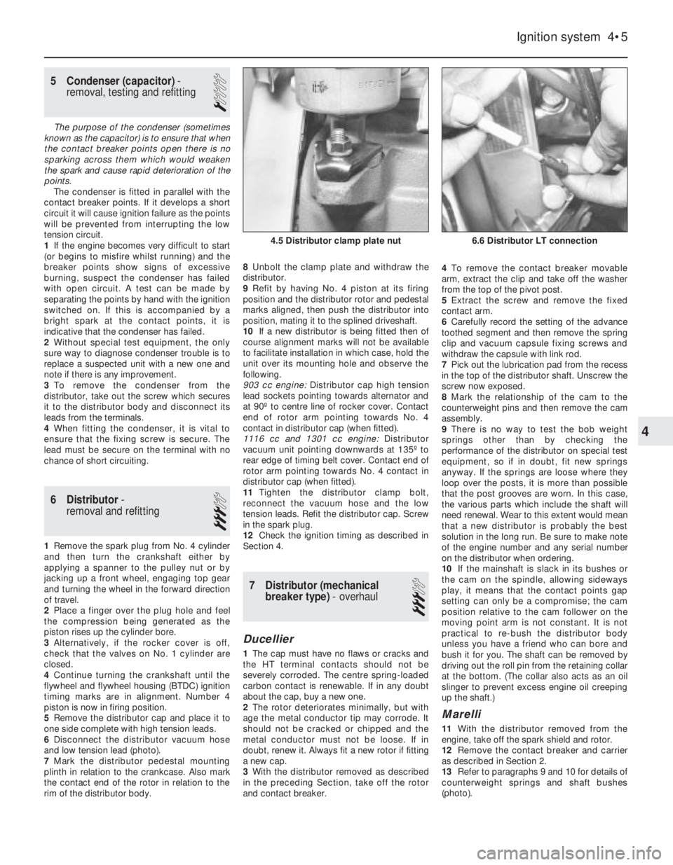
1Remove the spark plug from No. 4 cylinder
and then turn the crankshaft either by
applying a spanner to the pulley nut or by
jacking up a front wheel, engaging top gear
and turning the wheel in the forward direction
of travel.
2Place a finger over the plug hole and feel
the compression being generated as the
piston rises up the cylinder bore.
3Alternatively, if the rocker cover is off,
check that the valves on No. 1 cylinder are
closed.
4Continue turning the crankshaft until the
flywheel and flywheel housing (BTDC) ignition
timing marks are in alignment. Number 4
piston is now in firing position.
5Remove the distributor cap and place it to
one side complete with high tension leads.
6Disconnect the distributor vacuum hose
and low tension lead (photo).
7Mark the distributor pedestal mounting
plinth in relation to the crankcase. Also mark
the contact end of the rotor in relation to the
rim of the distributor body.8Unbolt the clamp plate and withdraw the
distributor.
9Refit by having No. 4 piston at its firing
position and the distributor rotor and pedestal
marks aligned, then push the distributor into
position, mating it to the splined driveshaft.
10If a new distributor is being fitted then of
course alignment marks will not be available
to facilitate installation in which case, hold the
unit over its mounting hole and observe the
following.
903 cc engine: Distributor cap high tension
lead sockets pointing towards alternator and
at 90º to centre line of rocker cover. Contact
end of rotor arm pointing towards No. 4
contact in distributor cap (when fitted).
1116 cc and 1301 cc engine: Distributor
vacuum unit pointing downwards at 135º to
rear edge of timing belt cover. Contact end of
rotor arm pointing towards No. 4 contact in
distributor cap (when fitted).
11Tighten the distributor clamp bolt,
reconnect the vacuum hose and the low
tension leads. Refit the distributor cap. Screw
in the spark plug.
12Check the ignition timing as described in
Section 4.
7 Distributor (mechanical
breaker type)- overhaul
3
Ducellier
1The cap must have no flaws or cracks and
the HT terminal contacts should not be
severely corroded. The centre spring-loaded
carbon contact is renewable. If in any doubt
about the cap, buy a new one.
2The rotor deteriorates minimally, but with
age the metal conductor tip may corrode. It
should not be cracked or chipped and the
metal conductor must not be loose. If in
doubt, renew it. Always fit a new rotor if fitting
a new cap.
3With the distributor removed as described
in the preceding Section, take off the rotor
and contact breaker.4To remove the contact breaker movable
arm, extract the clip and take off the washer
from the top of the pivot post.
5Extract the screw and remove the fixed
contact arm.
6Carefully record the setting of the advance
toothed segment and then remove the spring
clip and vacuum capsule fixing screws and
withdraw the capsule with link rod.
7Pick out the lubrication pad from the recess
in the top of the distributor shaft. Unscrew the
screw now exposed.
8Mark the relationship of the cam to the
counterweight pins and then remove the cam
assembly.
9There is no way to test the bob weight
springs other than by checking the
performance of the distributor on special test
equipment, so if in doubt, fit new springs
anyway. If the springs are loose where they
loop over the posts, it is more than possible
that the post grooves are worn. In this case,
the various parts which include the shaft will
need renewal. Wear to this extent would mean
that a new distributor is probably the best
solution in the long run. Be sure to make note
of the engine number and any serial number
on the distributor when ordering.
10If the mainshaft is slack in its bushes or
the cam on the spindle, allowing sideways
play, it means that the contact points gap
setting can only be a compromise; the cam
position relative to the cam follower on the
moving point arm is not constant. It is not
practical to re-bush the distributor body
unless you have a friend who can bore and
bush it for you. The shaft can be removed by
driving out the roll pin from the retaining collar
at the bottom. (The collar also acts as an oil
slinger to prevent excess engine oil creeping
up the shaft.)
Marelli
11With the distributor removed from the
engine, take off the spark shield and rotor.
12Remove the contact breaker and carrier
as described in Section 2.
13Refer to paragraphs 9 and 10 for details of
counterweight springs and shaft bushes
(photo).
Ignition system 4•5
6.6 Distributor LT connection4.5 Distributor clamp plate nut
4
Page 77 of 303
Reassembly
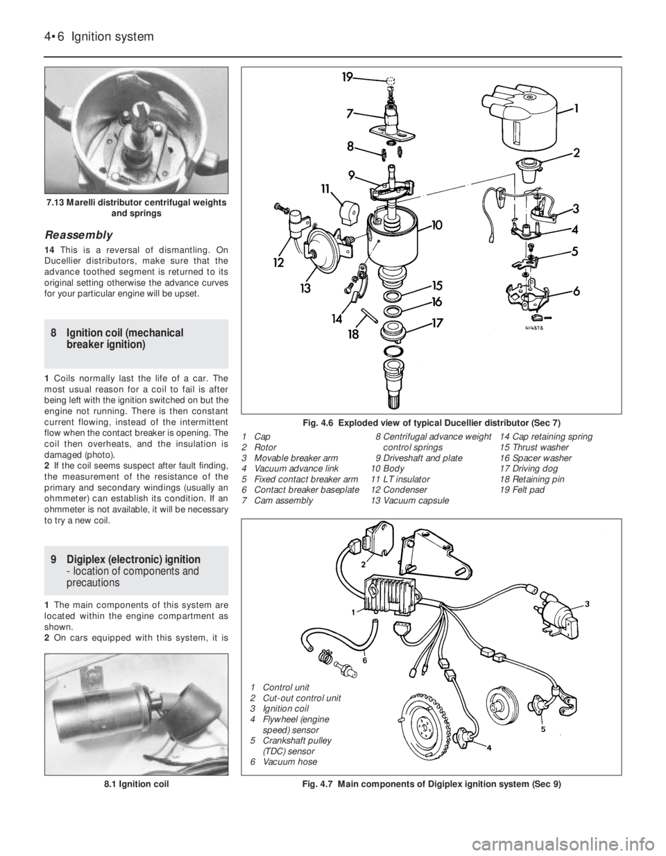
14This is a reversal of dismantling. On
Ducellier distributors, make sure that the
advance toothed segment is returned to its
original setting otherwise the advance curves
for your particular engine will be upset.
8 Ignition coil (mechanical
breaker ignition)
1Coils normally last the life of a car. The
most usual reason for a coil to fail is after
being left with the ignition switched on but the
engine not running. There is then constant
current flowing, instead of the intermittent
flow when the contact breaker is opening. The
coil then overheats, and the insulation is
damaged (photo).
2If the coil seems suspect after fault finding,
the measurement of the resistance of the
primary and secondary windings (usually an
ohmmeter) can establish its condition. If an
ohmmeter is not available, it will be necessary
to try a new coil.
9 Digiplex (electronic) ignition
- location of components and
precautions
1The main components of this system are
located within the engine compartment as
shown.
2On cars equipped with this system, it is
4•6 Ignition system
Fig. 4.7 Main components of Digiplex ignition system (Sec 9)8.1 Ignition coil
Fig. 4.6 Exploded view of typical Ducellier distributor (Sec 7)
1 Cap
2 Rotor
3 Movable breaker arm
4 Vacuum advance link
5 Fixed contact breaker arm
6 Contact breaker baseplate
7 Cam assembly8 Centrifugal advance weight
control springs
9 Driveshaft and plate
10 Body
11 LT insulator
12 Condenser
13 Vacuum capsule14 Cap retaining spring
15 Thrust washer
16 Spacer washer
17 Driving dog
18 Retaining pin
19 Felt pad
7.13 Marelli distributor centrifugal weights
and springs
1 Control unit
2 Cut-out control unit
3 Ignition coil
4 Flywheel (engine
speed) sensor
5 Crankshaft pulley
(TDC) sensor
6 Vacuum hose
Page 78 of 303
important that the following precautions are
observed.
3Never start the engine if the battery leads
are loose.
4Do not stop the engine by pulling off a
battery lead.
5Remove the control unit if ambient
temperature (paint drying oven) is above 80ºC
(176ºF).
6Never connect or disconnect the multi-plug
at the control unit unless the ignition is
switched off.
7Disconnect the battery negative lead before
carrying out electric body welding.10 Digiplex (electronic) ignition
- checks and adjustments
3
1Without special equipment, any work on the
system components should be restricted to
the following.
Engine speed sensor
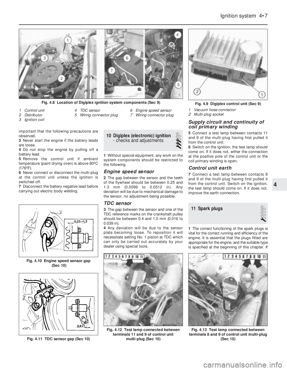
2The gap between the sensor and the teeth
of the flywheel should be between 0.25 and
1.3 mm (0.0099 to 0.0512 in). Any
deviation will be due to mechanical damage to
the sensor, no adjustment being possible.
TDC sensor
3The gap between the sensor and one of the
TDC reference marks on the crankshaft pulley
should be between 0.4 and 1.0 mm (0.016 to
0.039 in).
4Any deviation will be due to the sensor
plate becoming loose. To reposition it will
necessitate setting No. 1 piston at TDC which
can only be carried out accurately by your
dealer using special tools.
Supply circuit and continuity of
coil primary winding
5Connect a test lamp between contacts 11
and 9 of the multi-plug having first pulled it
from the control unit.
6Switch on the ignition, the test lamp should
come on. If it does not, either the connection
at the positive pole of the control unit or the
coil primary winding is open.
Control unit earth
7Connect a test lamp between contacts 8
and 9 of the multi-plug having first pulled it
from the control unit. Switch on the ignition,
the test lamp should come on. If it does not,
improve the earth connection.
11 Spark plugs
1
1The correct functioning of the spark plugs is
vital for the correct running and efficiency of the
engine. It is essential that the plugs fitted are
appropriate for the engine, and the suitable type
is specified at the beginning of this chapter. If
Ignition system 4•7
Fig. 4.9 Digiplex control unit (Sec 9)
1 Vacuum hose connector
2 Multi-plug socket
1 Control unit
2 Distributor
3 Ignition coil4 TDC sensor
5 Wiring connector plug6 Engine speed sensor
7 Wiring connector plug
Fig. 4.8 Location of Digiplex ignition system components (Sec 9)
Fig. 4.13 Test lamp connected between
terminals 8 and 9 of control unit multi-plug
(Sec 10)Fig. 4.12 Test lamp connected between
terminals 11 and 9 of control unit
multi-plug (Sec 10)
Fig. 4.11 TDC sensor gap (Sec 10)
Fig. 4.10 Engine speed sensor gap
(Sec 10)
4
Page 79 of 303
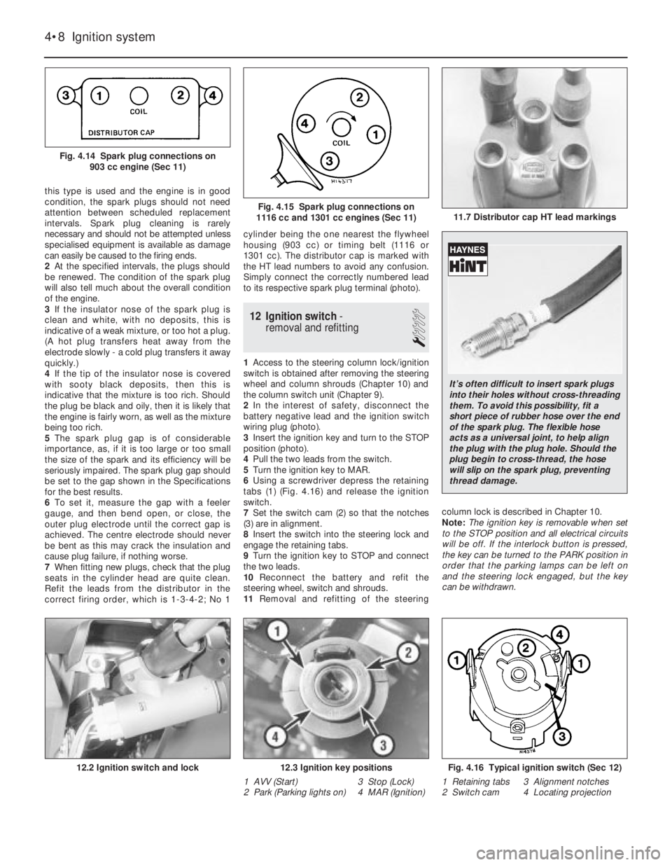
this type is used and the engine is in good
condition, the spark plugs should not need
attention between scheduled replacement
intervals. Spark plug cleaning is rarely
necessary and should not be attempted unless
specialised equipment is available as damage
can easily be caused to the firing ends.
2At the specified intervals, the plugs should
be renewed. The condition of the spark plug
will also tell much about the overall condition
of the engine.
3If the insulator nose of the spark plug is
clean and white, with no deposits, this is
indicative of a weak mixture, or too hot a plug.
(A hot plug transfers heat away from the
electrode slowly - a cold plug transfers it away
quickly.)
4If the tip of the insulator nose is covered
with sooty black deposits, then this is
indicative that the mixture is too rich. Should
the plug be black and oily, then it is likely that
the engine is fairly worn, as well as the mixture
being too rich.
5The spark plug gap is of considerable
importance, as, if it is too large or too small
the size of the spark and its efficiency will be
seriously impaired. The spark plug gap should
be set to the gap shown in the Specifications
for the best results.
6To set it, measure the gap with a feeler
gauge, and then bend open, or close, the
outer plug electrode until the correct gap is
achieved. The centre electrode should never
be bent as this may crack the insulation and
cause plug failure, if nothing worse.
7When fitting new plugs, check that the plug
seats in the cylinder head are quite clean.
Refit the leads from the distributor in the
correct firing order, which is 1-3-4-2; No 1cylinder being the one nearest the flywheel
housing (903 cc) or timing belt (1116 or
1301 cc). The distributor cap is marked with
the HT lead numbers to avoid any confusion.
Simply connect the correctly numbered lead
to its respective spark plug terminal (photo).
12 Ignition switch-
removal and refitting
1
1Access to the steering column lock/ignition
switch is obtained after removing the steering
wheel and column shrouds (Chapter 10) and
the column switch unit (Chapter 9).
2In the interest of safety, disconnect the
battery negative lead and the ignition switch
wiring plug (photo).
3Insert the ignition key and turn to the STOP
position (photo).
4Pull the two leads from the switch.
5Turn the ignition key to MAR.
6Using a screwdriver depress the retaining
tabs (1) (Fig. 4.16) and release the ignition
switch.
7Set the switch cam (2) so that the notches
(3) are in alignment.
8Insert the switch into the steering lock and
engage the retaining tabs.
9Turn the ignition key to STOP and connect
the two leads.
10Reconnect the battery and refit the
steering wheel, switch and shrouds.
11Removal and refitting of the steeringcolumn lock is described in Chapter 10.
Note: The ignition key is removable when set
to the STOP position and all electrical circuits
will be off. If the interlock button is pressed,
the key can be turned to the PARK position in
order that the parking lamps can be left on
and the steering lock engaged, but the key
can be withdrawn.
4•8 Ignition system
Fig. 4.16 Typical ignition switch (Sec 12)
1 Retaining tabs 3 Alignment notches
2 Switch cam 4 Locating projection12.3 Ignition key positions
1 AVV (Start) 3 Stop (Lock)
2 Park (Parking lights on) 4 MAR (Ignition)12.2 Ignition switch and lock
11.7 Distributor cap HT lead markingsFig. 4.15 Spark plug connections on
1116 cc and 1301 cc engines (Sec 11)
Fig. 4.14 Spark plug connections on
903 cc engine (Sec 11)
It’s often difficult to insert spark plugs
into their holes without cross-threading
them. To avoid this possibility, fit a
short piece of rubber hose over the end
of the spark plug. The flexible hose
acts as a universal joint, to help align
the plug with the plug hole. Should the
plug begin to cross-thread, the hose
will slip on the spark plug, preventing
thread damage.
Page 80 of 303
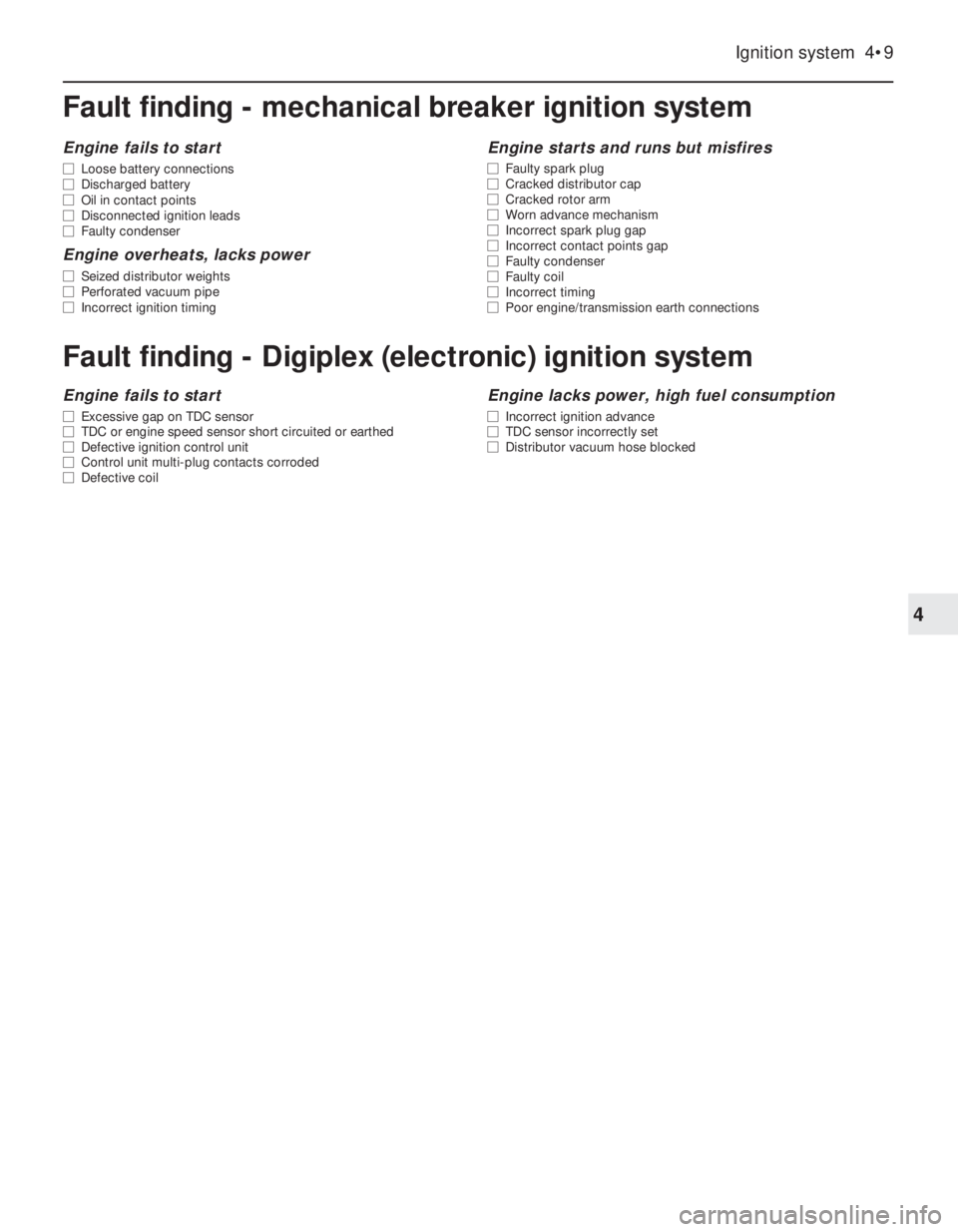
Fault finding - mechanical breaker ignition system
Ignition system 4•9
4
Engine fails to start
m mLoose battery connections
m mDischarged battery
m mOil in contact points
m mDisconnected ignition leads
m mFaulty condenser
Engine overheats, lacks power
m
mSeized distributor weights
m mPerforated vacuum pipe
m mIncorrect ignition timing
Engine starts and runs but misfires
m
mFaulty spark plug
m mCracked distributor cap
m mCracked rotor arm
m mWorn advance mechanism
m mIncorrect spark plug gap
m mIncorrect contact points gap
m mFaulty condenser
m mFaulty coil
m mIncorrect timing
m mPoor engine/transmission earth connections
Fault finding - Digiplex (electronic) ignition system
Engine fails to start
m
mExcessive gap on TDC sensor
m mTDC or engine speed sensor short circuited or earthed
m mDefective ignition control unit
m mControl unit multi-plug contacts corroded
m mDefective coil
Engine lacks power, high fuel consumption
m
mIncorrect ignition advance
m mTDC sensor incorrectly set
m mDistributor vacuum hose blocked