FIAT UNO 1983 Service Manual PDF
Manufacturer: FIAT, Model Year: 1983, Model line: UNO, Model: FIAT UNO 1983Pages: 303, PDF Size: 10.36 MB
Page 61 of 303
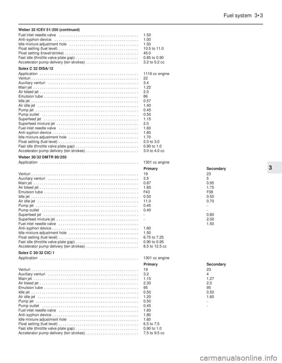
Weber 32 ICEV 51/250 (continued)
Fuel inlet needle valve . . . . . . . . . . . . . . . . . . . . . . . . . . . . . . . . . . . . . . 1.50
Anti-syphon device. . . . . . . . . . . . . . . . . . . . . . . . . . . . . . . . . . . . . . . . . 1.00
Idle mixture adjustment hole . . . . . . . . . . . . . . . . . . . . . . . . . . . . . . . . . 1.50
Float setting (fuel level) . . . . . . . . . . . . . . . . . . . . . . . . . . . . . . . . . . . . . . 10.5 to 11.0
Float setting (travel/stroke) . . . . . . . . . . . . . . . . . . . . . . . . . . . . . . . . . . . 45.0
Fast idle (throttle valve plate gap) . . . . . . . . . . . . . . . . . . . . . . . . . . . . . . 0.85 to 0.90
Accelerator pump delivery (ten strokes) . . . . . . . . . . . . . . . . . . . . . . . . . 3.2 to 5.2 cc
Solex C 32 DISA/12
Application . . . . . . . . . . . . . . . . . . . . . . . . . . . . . . . . . . . . . . . . . . . . . . . 1116 cc engine
Venturi . . . . . . . . . . . . . . . . . . . . . . . . . . . . . . . . . . . . . . . . . . . . . . . . . . . 22
Auxiliary venturi . . . . . . . . . . . . . . . . . . . . . . . . . . . . . . . . . . . . . . . . . . . 3.4
Main jet . . . . . . . . . . . . . . . . . . . . . . . . . . . . . . . . . . . . . . . . . . . . . . . . . . 1.22
Air bleed jet . . . . . . . . . . . . . . . . . . . . . . . . . . . . . . . . . . . . . . . . . . . . . . . 2.0
Emulsion tube . . . . . . . . . . . . . . . . . . . . . . . . . . . . . . . . . . . . . . . . . . . . . 86
Idle jet . . . . . . . . . . . . . . . . . . . . . . . . . . . . . . . . . . . . . . . . . . . . . . . . . . . 0.57
Air idle jet . . . . . . . . . . . . . . . . . . . . . . . . . . . . . . . . . . . . . . . . . . . . . . . . 1.40
Pump jet . . . . . . . . . . . . . . . . . . . . . . . . . . . . . . . . . . . . . . . . . . . . . . . . . 0.45
Pump outlet . . . . . . . . . . . . . . . . . . . . . . . . . . . . . . . . . . . . . . . . . . . . . . 0.50
Superfeed jet . . . . . . . . . . . . . . . . . . . . . . . . . . . . . . . . . . . . . . . . . . . . . 1.15
Superfeed mixture jet . . . . . . . . . . . . . . . . . . . . . . . . . . . . . . . . . . . . . . . 2.0
Fuel inlet needle valve . . . . . . . . . . . . . . . . . . . . . . . . . . . . . . . . . . . . . . 1.60
Anti-syphon device . . . . . . . . . . . . . . . . . . . . . . . . . . . . . . . . . . . . . . . . . 1.60
Idle mixture adjustment hole . . . . . . . . . . . . . . . . . . . . . . . . . . . . . . . . . 1.70
Float setting (fuel level) . . . . . . . . . . . . . . . . . . . . . . . . . . . . . . . . . . . . . . 2.0 to 3.0
Fast idle (throttle valve plate gap) . . . . . . . . . . . . . . . . . . . . . . . . . . . . . . 0.90 to 1.0
Accelerator pump delivery (ten strokes) . . . . . . . . . . . . . . . . . . . . . . . . . 3.0 to 4.0 cc
Weber 30/32 DMTR 90/250
Application . . . . . . . . . . . . . . . . . . . . . . . . . . . . . . . . . . . . . . . . . . . . . . . 1301 cc engine
Primary Secondary
Venturi . . . . . . . . . . . . . . . . . . . . . . . . . . . . . . . . . . . . . . . . . . . . . . . . . . . 19 23
Auxiliary venturi . . . . . . . . . . . . . . . . . . . . . . . . . . . . . . . . . . . . . . . . . . . 3.5 5
Main jet . . . . . . . . . . . . . . . . . . . . . . . . . . . . . . . . . . . . . . . . . . . . . . . . . . 0.87 0.95
Air bleed jet . . . . . . . . . . . . . . . . . . . . . . . . . . . . . . . . . . . . . . . . . . . . . . . 1.85 1.75
Emulsion tube . . . . . . . . . . . . . . . . . . . . . . . . . . . . . . . . . . . . . . . . . . . . . F43 F38
Idle jet . . . . . . . . . . . . . . . . . . . . . . . . . . . . . . . . . . . . . . . . . . . . . . . . . . . 0.50 0.50
Air idle jet . . . . . . . . . . . . . . . . . . . . . . . . . . . . . . . . . . . . . . . . . . . . . . . . 11.0 0.70
Pump jet . . . . . . . . . . . . . . . . . . . . . . . . . . . . . . . . . . . . . . . . . . . . . . . . . 0.45 -
Pump outlet . . . . . . . . . . . . . . . . . . . . . . . . . . . . . . . . . . . . . . . . . . . . . . 0.40 -
Superfeed jet . . . . . . . . . . . . . . . . . . . . . . . . . . . . . . . . . . . . . . . . . . . . . - 0.80
Superfeed mixture jet . . . . . . . . . . . . . . . . . . . . . . . . . . . . . . . . . . . . . . . - 2.00
Fuel inlet needle valve . . . . . . . . . . . . . . . . . . . . . . . . . . . . . . . . . . . . . . 1.50
Anti-syphon device . . . . . . . . . . . . . . . . . . . . . . . . . . . . . . . . . . . . . . . . . 1.60
Idle mixture adjustment hole . . . . . . . . . . . . . . . . . . . . . . . . . . . . . . . . . 1.50
Float setting (fuel level) . . . . . . . . . . . . . . . . . . . . . . . . . . . . . . . . . . . . . . 6.75 to 7.25
Fast idle (throttle valve plate gap) . . . . . . . . . . . . . . . . . . . . . . . . . . . . . . 0.90 to 0.95
Accelerator pump delivery (ten strokes) . . . . . . . . . . . . . . . . . . . . . . . . . 8.5 to 12.5 cc
Solex C 30/32 CIC/1
Application . . . . . . . . . . . . . . . . . . . . . . . . . . . . . . . . . . . . . . . . . . . . . . . 1301 cc engine
Primary Secondary
Venturi . . . . . . . . . . . . . . . . . . . . . . . . . . . . . . . . . . . . . . . . . . . . . . . . . . . 19 23
Auxiliary venturi . . . . . . . . . . . . . . . . . . . . . . . . . . . . . . . . . . . . . . . . . . . 3.2 4
Main jet . . . . . . . . . . . . . . . . . . . . . . . . . . . . . . . . . . . . . . . . . . . . . . . . . . 1.15 1.27
Air bleed jet . . . . . . . . . . . . . . . . . . . . . . . . . . . . . . . . . . . . . . . . . . . . . . . 2.30 2.0
Emulsion tube . . . . . . . . . . . . . . . . . . . . . . . . . . . . . . . . . . . . . . . . . . . . . 95 95
Idle jet . . . . . . . . . . . . . . . . . . . . . . . . . . . . . . . . . . . . . . . . . . . . . . . . . . . 0.50 0.50
Air idle jet . . . . . . . . . . . . . . . . . . . . . . . . . . . . . . . . . . . . . . . . . . . . . . . . 1.20 1.60
Pump jet . . . . . . . . . . . . . . . . . . . . . . . . . . . . . . . . . . . . . . . . . . . . . . . . . 0.50 -
Pump outlet . . . . . . . . . . . . . . . . . . . . . . . . . . . . . . . . . . . . . . . . . . . . . . 0.45 -
Fuel inlet needle valve . . . . . . . . . . . . . . . . . . . . . . . . . . . . . . . . . . . . . . 1.60
Anti-syphon device . . . . . . . . . . . . . . . . . . . . . . . . . . . . . . . . . . . . . . . . . 1.80
Idle mixture adjustment hole . . . . . . . . . . . . . . . . . . . . . . . . . . . . . . . . . 1.60
Float setting (fuel level) . . . . . . . . . . . . . . . . . . . . . . . . . . . . . . . . . . . . . . 6.5 to 7.5
Fast idle (throttle valve plate gap) . . . . . . . . . . . . . . . . . . . . . . . . . . . . . . 0.90 to 1.0
Accelerator pump delivery (ten strokes) . . . . . . . . . . . . . . . . . . . . . . . . . 7.5 to 9.5 cc
Fuel system 3•3
3
Page 62 of 303
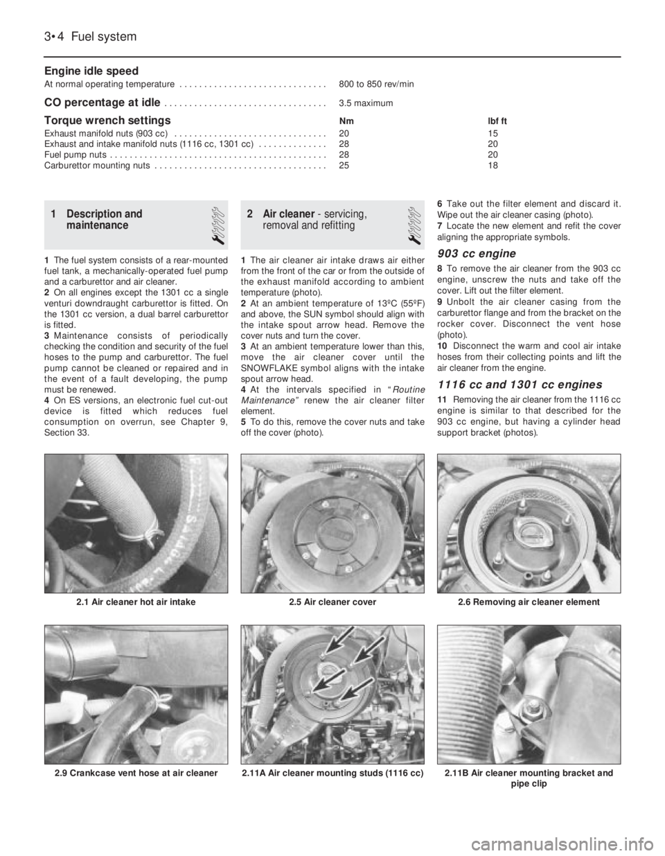
Engine idle speed
At normal operating temperature . . . . . . . . . . . . . . . . . . . . . . . . . . . . . . 800 to 850 rev/min
CO percentage at idle . . . . . . . . . . . . . . . . . . . . . . . . . . . . . . . . . 3.5 maximum
Torque wrench settingsNm lbf ft
Exhaust manifold nuts (903 cc) . . . . . . . . . . . . . . . . . . . . . . . . . . . . . . . 20 15
Exhaust and intake manifold nuts (1116 cc, 1301 cc) . . . . . . . . . . . . . . 28 20
Fuel pump nuts . . . . . . . . . . . . . . . . . . . . . . . . . . . . . . . . . . . . . . . . . . . . 28 20
Carburettor mounting nuts . . . . . . . . . . . . . . . . . . . . . . . . . . . . . . . . . . . 25 18
3•4 Fuel system
2.11B Air cleaner mounting bracket and
pipe clip2.11A Air cleaner mounting studs (1116 cc)2.9 Crankcase vent hose at air cleaner
1 Description and
maintenance
1
1The fuel system consists of a rear-mounted
fuel tank, a mechanically-operated fuel pump
and a carburettor and air cleaner.
2On all engines except the 1301 cc a single
venturi downdraught carburettor is fitted. On
the 1301 cc version, a dual barrel carburettor
is fitted.
3Maintenance consists of periodically
checking the condition and security of the fuel
hoses to the pump and carburettor. The fuel
pump cannot be cleaned or repaired and in
the event of a fault developing, the pump
must be renewed.
4On ES versions, an electronic fuel cut-out
device is fitted which reduces fuel
consumption on overrun, see Chapter 9,
Section 33.
2 Air cleaner- servicing,
removal and refitting
1
1The air cleaner air intake draws air either
from the front of the car or from the outside of
the exhaust manifold according to ambient
temperature (photo).
2At an ambient temperature of 13ºC (55ºF)
and above, the SUN symbol should align with
the intake spout arrow head. Remove the
cover nuts and turn the cover.
3At an ambient temperature lower than this,
move the air cleaner cover until the
SNOWFLAKE symbol aligns with the intake
spout arrow head.
4At the intervals specified in “Routine
Maintenance” renew the air cleaner filter
element.
5To do this, remove the cover nuts and take
off the cover (photo).6Take out the filter element and discard it.
Wipe out the air cleaner casing (photo).
7Locate the new element and refit the cover
aligning the appropriate symbols.903 cc engine
8To remove the air cleaner from the 903 cc
engine, unscrew the nuts and take off the
cover. Lift out the filter element.
9Unbolt the air cleaner casing from the
carburettor flange and from the bracket on the
rocker cover. Disconnect the vent hose
(photo).
10Disconnect the warm and cool air intake
hoses from their collecting points and lift the
air cleaner from the engine.
1116 cc and 1301 cc engines
11Removing the air cleaner from the 1116 cc
engine is similar to that described for the
903 cc engine, but having a cylinder head
support bracket (photos).
2.6 Removing air cleaner element
2.5 Air cleaner cover2.1 Air cleaner hot air intake
Page 63 of 303
12The air cleaner on the 1301 cc engine is
mounted on the four flange studs of the
carburettors, their nuts being accessible after
the air cleaner lid has been removed and the
filter element extracted.
13Refitting of all types of air cleaner is a
reversal of removal.
3 Fuel pump-
removal and refitting
2
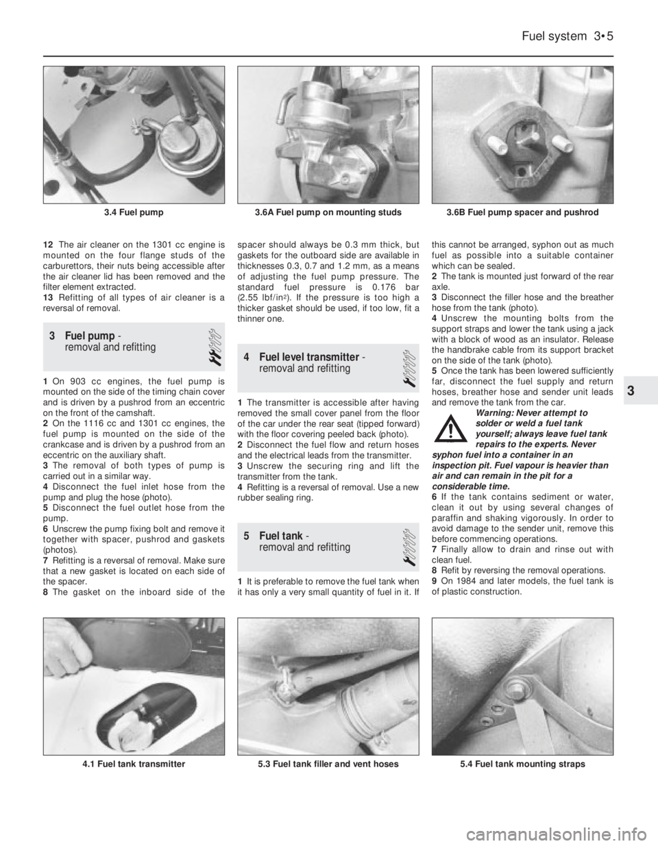
1On 903 cc engines, the fuel pump is
mounted on the side of the timing chain cover
and is driven by a pushrod from an eccentric
on the front of the camshaft.
2On the 1116 cc and 1301 cc engines, the
fuel pump is mounted on the side of the
crankcase and is driven by a pushrod from an
eccentric on the auxiliary shaft.
3The removal of both types of pump is
carried out in a similar way.
4Disconnect the fuel inlet hose from the
pump and plug the hose (photo).
5Disconnect the fuel outlet hose from the
pump.
6Unscrew the pump fixing bolt and remove it
together with spacer, pushrod and gaskets
(photos).
7Refitting is a reversal of removal. Make sure
that a new gasket is located on each side of
the spacer.
8The gasket on the inboard side of thespacer should always be 0.3 mm thick, but
gaskets for the outboard side are available in
thicknesses 0.3, 0.7 and 1.2 mm, as a means
of adjusting the fuel pump pressure. The
standard fuel pressure is 0.176 bar
(2.55 lbf/in
2). If the pressure is too high a
thicker gasket should be used, if too low, fit a
thinner one.
4 Fuel level transmitter-
removal and refitting
1
1The transmitter is accessible after having
removed the small cover panel from the floor
of the car under the rear seat (tipped forward)
with the floor covering peeled back (photo).
2Disconnect the fuel flow and return hoses
and the electrical leads from the transmitter.
3Unscrew the securing ring and lift the
transmitter from the tank.
4Refitting is a reversal of removal. Use a new
rubber sealing ring.
5 Fuel tank-
removal and refitting
1
1It is preferable to remove the fuel tank when
it has only a very small quantity of fuel in it. Ifthis cannot be arranged, syphon out as much
fuel as possible into a suitable container
which can be sealed.
2The tank is mounted just forward of the rear
axle.
3Disconnect the filler hose and the breather
hose from the tank (photo).
4Unscrew the mounting bolts from the
support straps and lower the tank using a jack
with a block of wood as an insulator. Release
the handbrake cable from its support bracket
on the side of the tank (photo).
5Once the tank has been lowered sufficiently
far, disconnect the fuel supply and return
hoses, breather hose and sender unit leads
and remove the tank from the car.
Warning: Never attempt to
solder or weld a fuel tank
yourself; always leave fuel tank
repairs to the experts. Never
syphon fuel into a container in an
inspection pit. Fuel vapour is heavier than
air and can remain in the pit for a
considerable time.
6If the tank contains sediment or water,
clean it out by using several changes of
paraffin and shaking vigorously. In order to
avoid damage to the sender unit, remove this
before commencing operations.
7Finally allow to drain and rinse out with
clean fuel.
8Refit by reversing the removal operations.
9On 1984 and later models, the fuel tank is
of plastic construction.
Fuel system 3•5
3.6B Fuel pump spacer and pushrod3.6A Fuel pump on mounting studs3.4 Fuel pump
5.4 Fuel tank mounting straps5.3 Fuel tank filler and vent hoses4.1 Fuel tank transmitter
3
Page 64 of 303
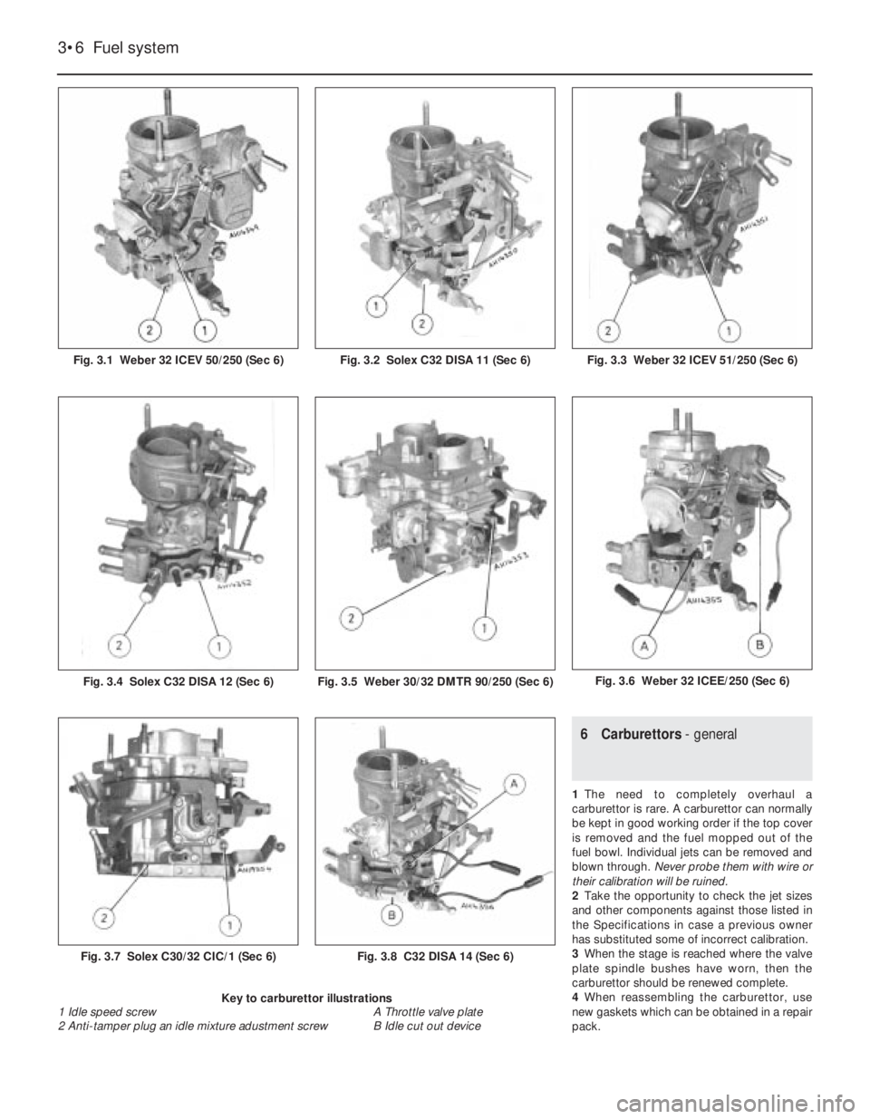
6 Carburettors- general
1The need to completely overhaul a
carburettor is rare. A carburettor can normally
be kept in good working order if the top cover
is removed and the fuel mopped out of the
fuel bowl. Individual jets can be removed and
blown through. Never probe them with wire or
their calibration will be ruined.
2Take the opportunity to check the jet sizes
and other components against those listed in
the Specifications in case a previous owner
has substituted some of incorrect calibration.
3When the stage is reached where the valve
plate spindle bushes have worn, then the
carburettor should be renewed complete.
4When reassembling the carburettor, use
new gaskets which can be obtained in a repair
pack.
3•6 Fuel system
Fig. 3.8 C32 DISA 14 (Sec 6)
Fig. 3.6 Weber 32 ICEE/250 (Sec 6)Fig. 3.5 Weber 30/32 DMTR 90/250 (Sec 6)Fig. 3.4 Solex C32 DISA 12 (Sec 6)
Fig. 3.7 Solex C30/32 CIC/1 (Sec 6)
Fig. 3.3 Weber 32 ICEV 51/250 (Sec 6)Fig. 3.2 Solex C32 DISA 11 (Sec 6)Fig. 3.1 Weber 32 ICEV 50/250 (Sec 6)
Key to carburettor illustrations
1 Idle speed screw A Throttle valve plate
2 Anti-tamper plug an idle mixture adustment screw B Idle cut out device
Page 65 of 303
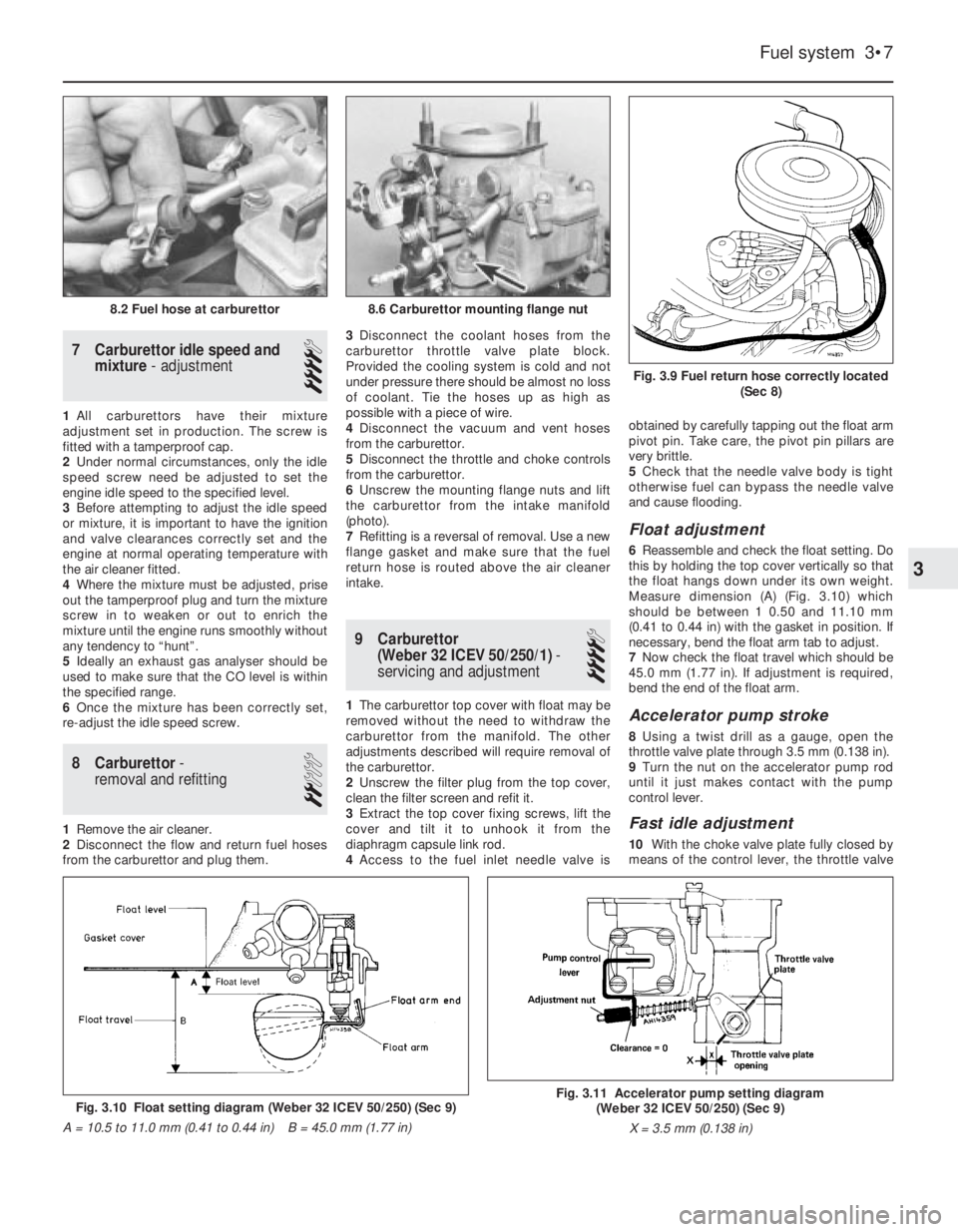
7 Carburettor idle speed and
mixture- adjustment
4
1All carburettors have their mixture
adjustment set in production. The screw is
fitted with a tamperproof cap.
2Under normal circumstances, only the idle
speed screw need be adjusted to set the
engine idle speed to the specified level.
3Before attempting to adjust the idle speed
or mixture, it is important to have the ignition
and valve clearances correctly set and the
engine at normal operating temperature with
the air cleaner fitted.
4Where the mixture must be adjusted, prise
out the tamperproof plug and turn the mixture
screw in to weaken or out to enrich the
mixture until the engine runs smoothly without
any tendency to “hunt”.
5Ideally an exhaust gas analyser should be
used to make sure that the CO level is within
the specified range.
6Once the mixture has been correctly set,
re-adjust the idle speed screw.
8 Carburettor-
removal and refitting
2
1Remove the air cleaner.
2Disconnect the flow and return fuel hoses
from the carburettor and plug them.3Disconnect the coolant hoses from the
carburettor throttle valve plate block.
Provided the cooling system is cold and not
under pressure there should be almost no loss
of coolant. Tie the hoses up as high as
possible with a piece of wire.
4Disconnect the vacuum and vent hoses
from the carburettor.
5Disconnect the throttle and choke controls
from the carburettor.
6Unscrew the mounting flange nuts and lift
the carburettor from the intake manifold
(photo).
7Refitting is a reversal of removal. Use a new
flange gasket and make sure that the fuel
return hose is routed above the air cleaner
intake.
9 Carburettor
(Weber 32 ICEV 50/250/1)-
servicing and adjustment
4
1The carburettor top cover with float may be
removed without the need to withdraw the
carburettor from the manifold. The other
adjustments described will require removal of
the carburettor.
2Unscrew the filter plug from the top cover,
clean the filter screen and refit it.
3Extract the top cover fixing screws, lift the
cover and tilt it to unhook it from the
diaphragm capsule link rod.
4Access to the fuel inlet needle valve isobtained by carefully tapping out the float arm
pivot pin. Take care, the pivot pin pillars are
very brittle.
5Check that the needle valve body is tight
otherwise fuel can bypass the needle valve
and cause flooding.
Float adjustment
6Reassemble and check the float setting. Do
this by holding the top cover vertically so that
the float hangs down under its own weight.
Measure dimension (A) (Fig. 3.10) which
should be between 1 0.50 and 11.10 mm
(0.41 to 0.44 in) with the gasket in position. If
necessary, bend the float arm tab to adjust.
7Now check the float travel which should be
45.0 mm (1.77 in). If adjustment is required,
bend the end of the float arm.
Accelerator pump stroke
8Using a twist drill as a gauge, open the
throttle valve plate through 3.5 mm (0.138 in).
9Turn the nut on the accelerator pump rod
until it just makes contact with the pump
control lever.
Fast idle adjustment
10With the choke valve plate fully closed by
means of the control lever, the throttle valve
Fuel system 3•7
Fig. 3.9 Fuel return hose correctly located
(Sec 8)
8.6 Carburettor mounting flange nut8.2 Fuel hose at carburettor
Fig. 3.10 Float setting diagram (Weber 32 ICEV 50/250) (Sec 9)
A = 10.5 to 11.0 mm (0.41 to 0.44 in) B = 45.0 mm (1.77 in)Fig. 3.11 Accelerator pump setting diagram
(Weber 32 ICEV 50/250) (Sec 9)
X = 3.5 mm (0.138 in)
3
Page 66 of 303
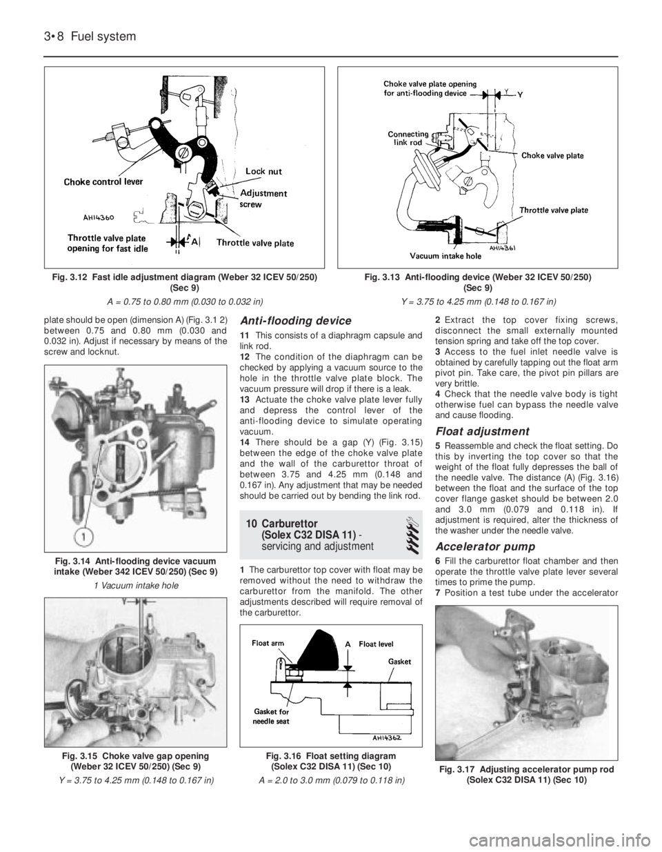
plate should be open (dimension A) (Fig. 3.1 2)
between 0.75 and 0.80 mm (0.030 and
0.032 in). Adjust if necessary by means of the
screw and locknut.Anti-flooding device
11This consists of a diaphragm capsule and
link rod.
12The condition of the diaphragm can be
checked by applying a vacuum source to the
hole in the throttle valve plate block. The
vacuum pressure will drop if there is a leak.
13Actuate the choke valve plate lever fully
and depress the control lever of the
anti-flooding device to simulate operating
vacuum.
14There should be a gap (Y) (Fig. 3.15)
between the edge of the choke valve plate
and the wall of the carburettor throat of
between 3.75 and 4.25 mm (0.148 and
0.167 in). Any adjustment that may be needed
should be carried out by bending the link rod.
10 Carburettor
(Solex C32 DISA 11)-
servicing and adjustment
4
1The carburettor top cover with float may be
removed without the need to withdraw the
carburettor from the manifold. The other
adjustments described will require removal of
the carburettor.2Extract the top cover fixing screws,
disconnect the small externally mounted
tension spring and take off the top cover.
3Access to the fuel inlet needle valve is
obtained by carefully tapping out the float arm
pivot pin. Take care, the pivot pin pillars are
very brittle.
4Check that the needle valve body is tight
otherwise fuel can bypass the needle valve
and cause flooding.
Float adjustment
5Reassemble and check the float setting. Do
this by inverting the top cover so that the
weight of the float fully depresses the ball of
the needle valve. The distance (A) (Fig. 3.16)
between the float and the surface of the top
cover flange gasket should be between 2.0
and 3.0 mm (0.079 and 0.118 in). If
adjustment is required, alter the thickness of
the washer under the needle valve.
Accelerator pump
6Fill the carburettor float chamber and then
operate the throttle valve plate lever several
times to prime the pump.
7Position a test tube under the accelerator
3•8 Fuel system
Fig. 3.16 Float setting diagram
(Solex C32 DISA 11) (Sec 10)
A = 2.0 to 3.0 mm (0.079 to 0.118 in)
Fig. 3.17 Adjusting accelerator pump rod
(Solex C32 DISA 11) (Sec 10)
Fig. 3.15 Choke valve gap opening
(Weber 32 ICEV 50/250) (Sec 9)
Y = 3.75 to 4.25 mm (0.148 to 0.167 in)
Fig. 3.14 Anti-flooding device vacuum
intake (Weber 342 ICEV 50/250) (Sec 9)
1 Vacuum intake hole
Fig. 3.12 Fast idle adjustment diagram (Weber 32 ICEV 50/250)
(Sec 9)
A = 0.75 to 0.80 mm (0.030 to 0.032 in)Fig. 3.13 Anti-flooding device (Weber 32 ICEV 50/250)
(Sec 9)
Y = 3.75 to 4.25 mm (0.148 to 0.167 in)
Page 67 of 303
pump jet and give ten full strokes of the
throttle lever, pausing between each stroke to
allow fuel to finish dripping.
8The total volume of fuel collected should be
between 2.5 and 4.5 cc. Adjust the nut on the
pump control and if necessary to increase or
decrease the volume of fuel ejected.
Fast idle adjustment
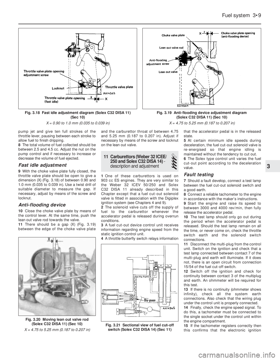
9With the choke valve plate fully closed, the
throttle valve plate should be open to give a
dimension (X) (Fig. 3.18) of between 0.90 and
1.0 mm (0.035 to 0.039 in). Use a twist drill of
suitable diameter to measure the gap. If
necessary, adjust by means of the screw and
locknut.
Anti-flooding device
10Close the choke valve plate by means of
the control lever. At the same time, push the
lean out valve rod towards the valve.
11There should be a gap (X) (Fig. 3.19)
between the edge of the choke valve plateand the carburettor throat of between 4.75
and 5.25 mm (0.187 to 0.207 in). Adjust if
necessary by means of the screw and locknut
on the lean out valve.
11 Carburettors (Weber 32 ICEE/
250 and Solex C32 DISA 14)-
description and adjustment
4
1One of these carburettors is used on
903 cc ES engines. They are very similar to
the Weber 32 ICEV 50/250 and Solex
C32 DISA 11 already described in this
Chapter except that a fuel cut-out solenoid
valve is fitted in association with the Digiplex
ignition system (see Chapters 4 and 9).
2The solenoid valve cuts off the supply of
fuel to the carburettor whenever the
accelerator pedal is released during overrun
conditions.
3A fuel cut-out device control unit receives
information regarding engine speed from the
static ignition control unit.
4A throttle butterfly switch relays informationthat the accelerator pedal is in the released
state.
5At certain minimum idle speeds during
deceleration, the fuel cut-out solenoid valve is
re-energised so that engine idling is
maintained without the tendency to cut out.
6The Solex type control unit varies the fuel
cut-out point according to the deceleration
value.Fault testing
7Should a fault develop, connect a test lamp
between the fuel cut-out solenoid switch and
a good earth.
8Connect a reliable tachometer to the engine
in accordance with the maker’s instructions.
9Start the engine and raise its speed to
between 3000 and 4000 rev/min, then fully
release the accelerator pedal.
10The test lamp should only go out during
the period when the accelerator pedal is
released. Should the test lamp remain on all
the time, or never come on, check the throttle
switch earth and the solenoid switch
connections.
11Disconnect the multi-plug from the control
unit. Switch on the ignition and check that a
test lamp connected between contact 7 of the
multi-plug and earth will illuminate. If it does
not, there is an open circuit from connection
15/54 of the fuel cut-off switch.
12Switch off the ignition and check for
continuity between contact 3 of the multiplug
and earth. An ohmmeter will be required for
this test.
13If there is no continuity (ohmmeter shows
infinity), check all the system earth
connections. Also check that the wiring plug
under the control unit is properly connected.
14Finally, check the engine speed signal. To
do this, a tachometer must be connected to
the single socket under the control unit within
the engine compartment.
15If the tachometer registers correctly then
this confirms that the electronic ignition
Fuel system 3•9
Fig. 3.18 Fast idle adjustment diagram (Solex C32 DISA 11)
(Sec 10)
X = 0.90 to 1.0 mm (0.035 to 0.039 in)Fig. 3.19 Anti-flooding device adjustment diagram
(Solex C32 DISA 11) (Sec 10)
X = 4.75 to 5.25 mm (0.187 to 0.207 in)
Fig. 3.21 Sectional view of fuel cut-off
switch (Solex C32 DISA 14) (Sec 11)
Fig. 3.20 Moving lean out valve rod
(Solex C32 DISA 11) (Sec 10)
X = 4.75 to 5.25 mm (0.187 to 0.207 in)
3
Page 68 of 303
control unit is functioning, if the tachometer
does not register, renew the ignition control
unit.
16If a replacement carburettor is to be fitted,
only fit the Solex assembly including the
control module, even if a Weber was originally
fitted.
12 Carburettor
(Weber 32 ICEV 51/250)-
servicing and adjustment
4
1This carburettor, fitted to 1116 cc engines,
is very similar to the unit described in Sec-
tion 9.
2The fast idle adjustment procedure is
identical, but note that dimension (A) (Fig.
3.12) should be between 0.85 and 0.90 mm
(0.033 and 0.035 in).
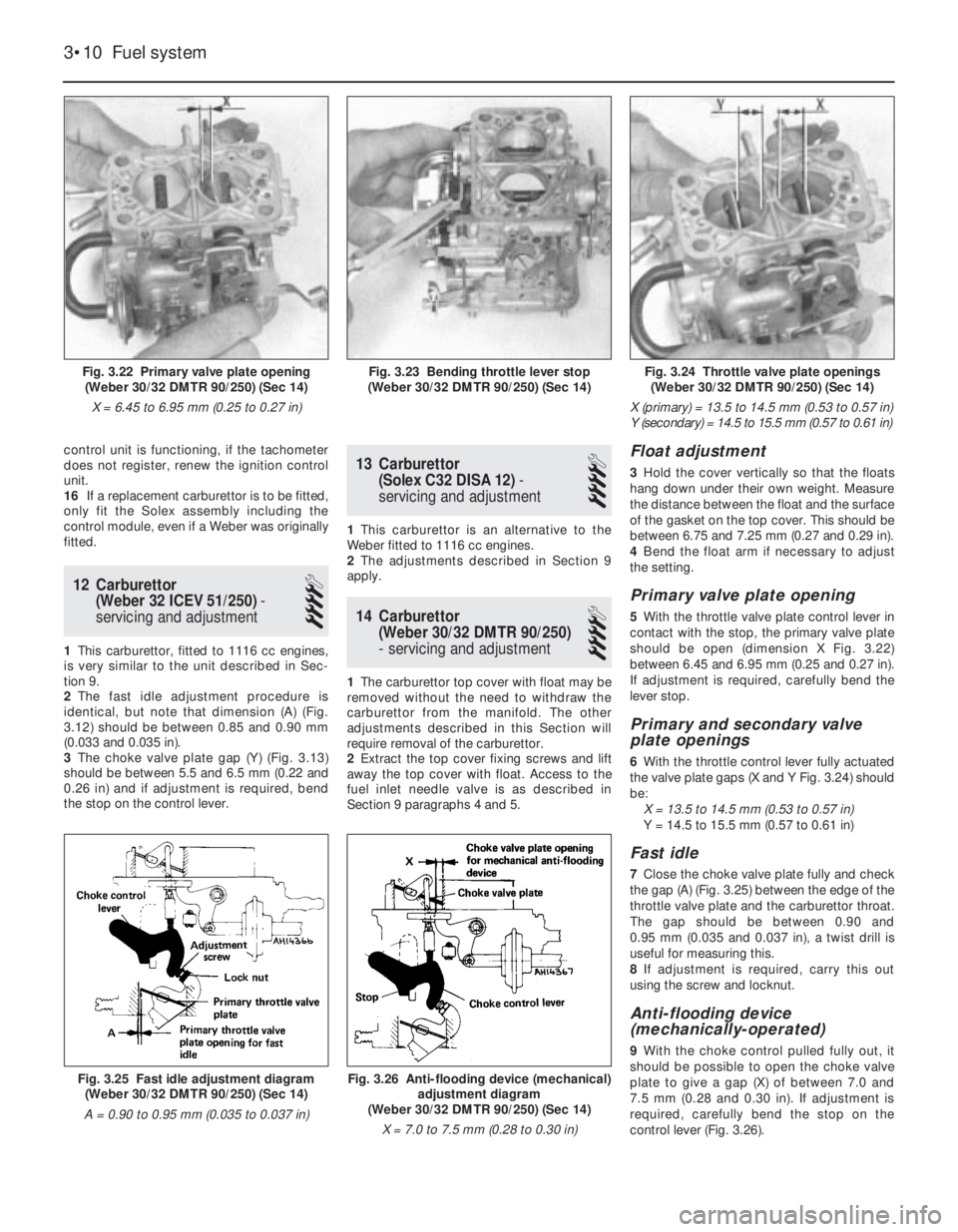
3The choke valve plate gap (Y) (Fig. 3.13)
should be between 5.5 and 6.5 mm (0.22 and
0.26 in) and if adjustment is required, bend
the stop on the control lever.
13 Carburettor
(Solex C32 DISA 12)-
servicing and adjustment
4
1This carburettor is an alternative to the
Weber fitted to 1116 cc engines.
2The adjustments described in Section 9
apply.
14 Carburettor
(Weber 30/32 DMTR 90/250)
- servicing and adjustment
4
1The carburettor top cover with float may be
removed without the need to withdraw the
carburettor from the manifold. The other
adjustments described in this Section will
require removal of the carburettor.
2Extract the top cover fixing screws and lift
away the top cover with float. Access to the
fuel inlet needle valve is as described in
Section 9 paragraphs 4 and 5.
Float adjustment
3Hold the cover vertically so that the floats
hang down under their own weight. Measure
the distance between the float and the surface
of the gasket on the top cover. This should be
between 6.75 and 7.25 mm (0.27 and 0.29 in).
4Bend the float arm if necessary to adjust
the setting.
Primary valve plate opening
5With the throttle valve plate control lever in
contact with the stop, the primary valve plate
should be open (dimension X Fig. 3.22)
between 6.45 and 6.95 mm (0.25 and 0.27 in).
If adjustment is required, carefully bend the
lever stop.
Primary and secondary valve
plate openings
6With the throttle control lever fully actuated
the valve plate gaps (X and Y Fig. 3.24) should
be:
X = 13.5 to 14.5 mm (0.53 to 0.57 in)
Y = 14.5 to 15.5 mm (0.57 to 0.61 in)
Fast idle
7Close the choke valve plate fully and check
the gap (A) (Fig. 3.25) between the edge of the
throttle valve plate and the carburettor throat.
The gap should be between 0.90 and
0.95 mm (0.035 and 0.037 in), a twist drill is
useful for measuring this.
8If adjustment is required, carry this out
using the screw and locknut.
Anti-flooding device
(mechanically-operated)
9With the choke control pulled fully out, it
should be possible to open the choke valve
plate to give a gap (X) of between 7.0 and
7.5 mm (0.28 and 0.30 in). If adjustment is
required, carefully bend the stop on the
control lever (Fig. 3.26).
3•10 Fuel system
Fig. 3.26 Anti-flooding device (mechanical)
adjustment diagram
(Weber 30/32 DMTR 90/250) (Sec 14)
X = 7.0 to 7.5 mm (0.28 to 0.30 in)Fig. 3.25 Fast idle adjustment diagram
(Weber 30/32 DMTR 90/250) (Sec 14)
A = 0.90 to 0.95 mm (0.035 to 0.037 in)
Fig. 3.24 Throttle valve plate openings
(Weber 30/32 DMTR 90/250) (Sec 14)
X (primary) = 13.5 to 14.5 mm (0.53 to 0.57 in)
Y (secondary) = 14.5 to 15.5 mm (0.57 to 0.61 in)Fig. 3.23 Bending throttle lever stop
(Weber 30/32 DMTR 90/250) (Sec 14)Fig. 3.22 Primary valve plate opening
(Weber 30/32 DMTR 90/250) (Sec 14)
X = 6.45 to 6.95 mm (0.25 to 0.27 in)
Page 69 of 303
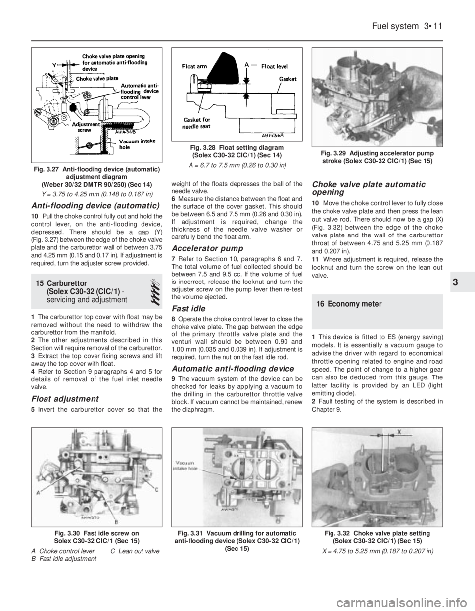
Anti-flooding device (automatic)
10Pull the choke control fully out and hold the
control lever, on the anti-flooding device,
depressed. There should be a gap (Y)
(Fig. 3.27) between the edge of the choke valve
plate and the carburettor wall of between 3.75
and 4.25 mm (0.15 and 0.17 in). If adjustment is
required, turn the adjuster screw provided.
15 Carburettor
(Solex C30-32 (CIC/1)-
servicing and adjustment
4
1The carburettor top cover with float may be
removed without the need to withdraw the
carburettor from the manifold.
2The other adjustments described in this
Section will require removal of the carburettor.
3Extract the top cover fixing screws and lift
away the top cover with float.
4Refer to Section 9 paragraphs 4 and 5 for
details of removal of the fuel inlet needle
valve.
Float adjustment
5Invert the carburettor cover so that theweight of the floats depresses the ball of the
needle valve.
6Measure the distance between the float and
the surface of the cover gasket. This should
be between 6.5 and 7.5 mm (0.26 and 0.30 in).
If adjustment is required, change the
thickness of the needle valve washer or
carefully bend the float arm.
Accelerator pump
7Refer to Section 10, paragraphs 6 and 7.
The total volume of fuel collected should be
between 7.5 and 9.5 cc. If the volume of fuel
is incorrect, release the locknut and turn the
adjuster screw on the pump lever then re-test
the volume ejected.
Fast idle
8Operate the choke control lever to close the
choke valve plate. The gap between the edge
of the primary throttle valve plate and the
venturi wall should be between 0.90 and
1.00 mm (0.035 and 0.039 in). If adjustment is
required, turn the nut on the fast idle rod.
Automatic anti-flooding device
9The vacuum system of the device can be
checked for leaks by applying a vacuum to
the drilling in the carburettor throttle valve
block. If vacuum cannot be maintained, renew
the diaphragm.
Choke valve plate automatic
opening
10Move the choke control lever to fully close
the choke valve plate and then press the lean
out valve rod. There should now be a gap (X)
(Fig. 3.32) between the edge of the choke
valve plate and the wall of the carburettor
throat of between 4.75 and 5.25 mm (0.187
and 0.207 in).
11Where adjustment is required, release the
locknut and turn the screw on the lean out
valve.
16 Economy meter
1This device is fitted to ES (energy saving)
models. It is essentially a vacuum gauge to
advise the driver with regard to economical
throttle opening related to engine and road
speed. The point of change to a higher gear
can also be deduced from this gauge. The
latter facility is provided by an LED (light
emitting diode).
2Fault testing of the system is described in
Chapter 9.
Fuel system 3•11
Fig. 3.29 Adjusting accelerator pump
stroke (Solex C30-32 CIC/1) (Sec 15)Fig. 3.28 Float setting diagram
(Solex C30-32 CIC/1) (Sec 14)
A = 6.7 to 7.5 mm (0.26 to 0.30 in)
Fig. 3.32 Choke valve plate setting
(Solex C30-32 CIC/1) (Sec 15)
X = 4.75 to 5.25 mm (0.187 to 0.207 in)Fig. 3.30 Fast idle screw on
Solex C30-32 CIC/1 (Sec 15)
A Choke control lever C Lean out valve
B Fast idle adjustmentFig. 3.31 Vacuum drilling for automatic
anti-flooding device (Solex C30-32 CIC/1)
(Sec 15)
3
Fig. 3.27 Anti-flooding device (automatic)
adjustment diagram
(Weber 30/32 DMTR 90/250) (Sec 14)
Y = 3.75 to 4.25 mm (0.148 to 0.167 in)
Page 70 of 303
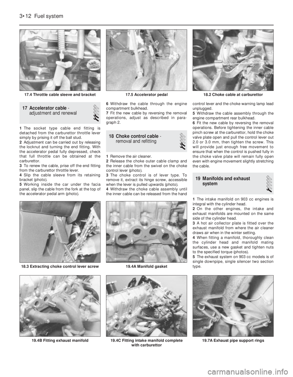
19.7A Exhaust pipe support rings
17 Accelerator cable-
adjustment and renewal
2
1The socket type cable end fitting is
detached from the carburettor throttle lever
simply by prising it off the ball stud.
2Adjustment can be carried out by releasing
the locknut and turning the end fitting. With
the accelerator pedal fully depressed, check
that full throttle can be obtained at the
carburettor.
3To renew the cable, prise off the end fitting
from the carburettor throttle lever.
4Slip the cable sleeve from its retaining
bracket (photo).
5Working inside the car under the facia
panel, slip the cable from the fork at the top of
the accelerator pedal arm (photo). 6Withdraw the cable through the engine
compartment bulkhead.
7Fit the new cable by reversing the removal
operations, adjust as described in para-
graph 2.
18 Choke control cable-
removal and refitting
2
1Remove the air cleaner.
2Release the choke outer cable clamp and
the inner cable from the swivel on the choke
control lever (photo).
3The choke control is of lever type. To
remove it, extract its hinge screw, accessible
when the lever is pulled upwards (photo).
4Withdraw the choke cable assembly until
the inner cable can be released from the handcontrol lever and the choke warning lamp lead
unplugged.
5Withdraw the cable assembly through the
engine compartment rear bulkhead.
6Fit the new cable by reversing the removal
operations. Before tightening the inner cable
pinch screw at the carburettor, hold the choke
valve plate open and pull the control lever out
2.0 or 3.0 mm, then tighten the screw. This
will provide just enough free movement to
ensure that when the control is pushed fully in
the choke valve plate will remain fully open
even with engine movement slightly stretching
the cable.
19 Manifolds and exhaust
system
1
1The intake manifold on 903 cc engines is
integral with the cylinder head.
2On the other engines, the intake and
exhaust manifolds are mounted on the same
side of the cylinder head.
3A hot air collector plate is fitted over the
exhaust manifold from where the air cleaner
draws air when in the winter setting.
4When fitting a manifold, thoroughly clean
the cylinder head and manifold mating
surfaces, use a new gasket and tighten nuts
to the specified torque (photos).
5The exhaust system on 903 cc models is of
single downpipe, single silencer two section
type.
3•12 Fuel system
19.4C Fitting intake manifold complete
with carburettor19.4B Fitting exhaust manifold
19.4A Manifold gasket18.3 Extracting choke control lever screw
18.2 Choke cable at carburettor17.5 Accelerator pedal17.4 Throttle cable sleeve and bracket