FORD FESTIVA 1991 Service Manual
Manufacturer: FORD, Model Year: 1991, Model line: FESTIVA, Model: FORD FESTIVA 1991Pages: 454, PDF Size: 9.53 MB
Page 251 of 454
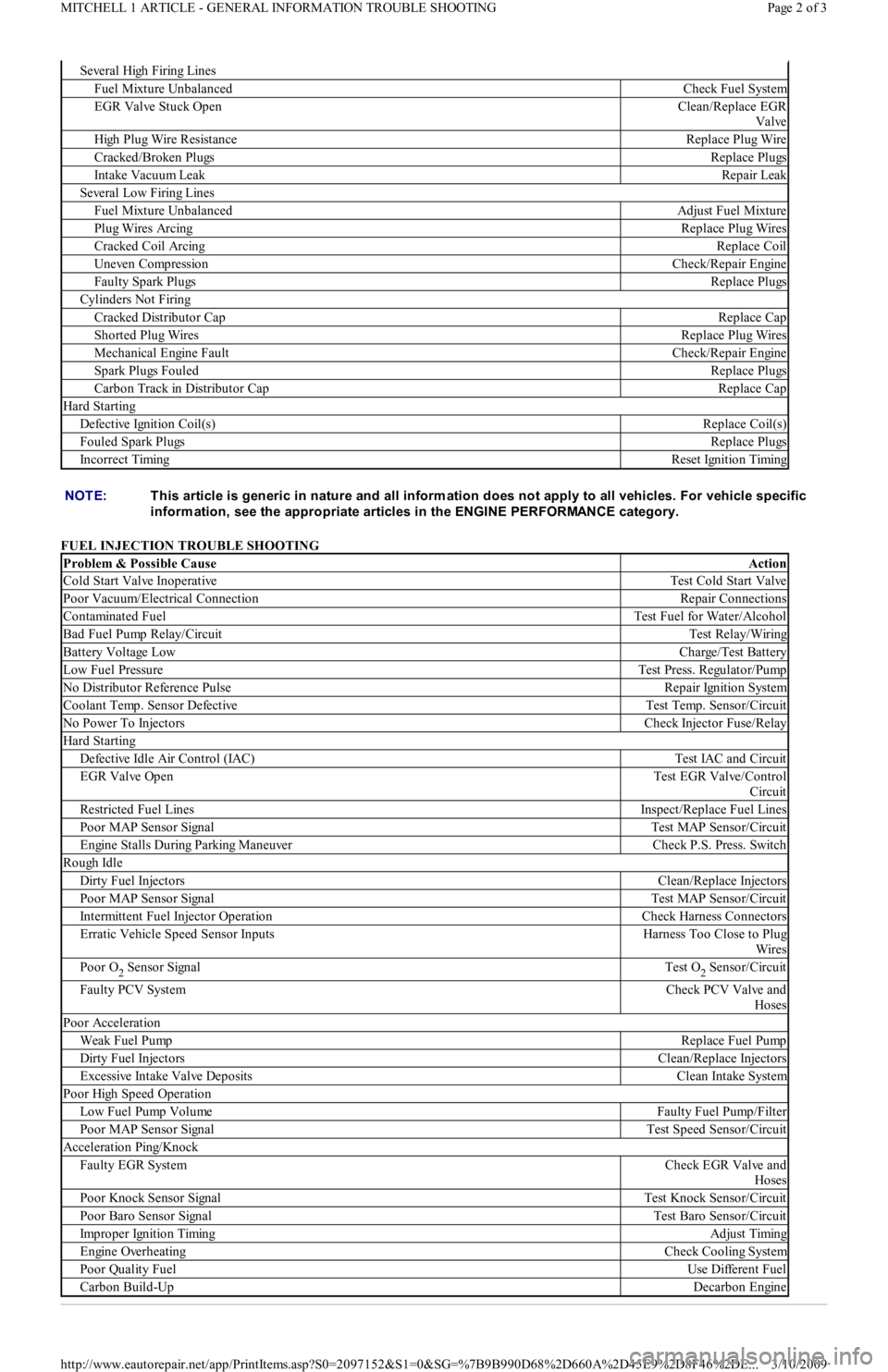
FUEL INJECTION TROUBLE SHOOTING
Se ve r a l High F ir in g Lin e s
Fuel Mixture UnbalancedCheck Fuel System
EGR Valve Stuck OpenClean/Replace EGR
Valve
High Plug Wire ResistanceReplace Plug Wire
Cracked/Broken PlugsReplace Plugs
Intake Vacuum LeakRepair Leak
Several Low Firing Lines
Fuel Mixture UnbalancedAdjust Fuel Mixture
Plug Wires ArcingReplace Plug Wires
Cracked Coil ArcingReplace Coil
Uneven CompressionCheck/Repair Engine
Faulty Spark PlugsReplace Plugs
Cylinders Not Firing
Cracked Distributor CapReplace Cap
Shorted Plug WiresReplace Plug Wires
Mechanical Engine FaultCheck/Repair Engine
Spark Plugs FouledReplace Plugs
Carbon Track in Distributor CapReplace Cap
Hard Starting
Defective Ignition Coil(s)Replace Coil(s)
Fouled Spark PlugsReplace Plugs
Incorrect TimingReset Ignition Timing
NOTE:T his article is generic in nature and all inform ation does not apply to all vehicles. For vehicle specific
inform ation, see the appropriate articles in the ENGINE PERFORMANCE category.
Problem & Possible CauseAction
Cold Start Valve InoperativeTest Cold Start Valve
Poor Vacuum/Electrical ConnectionRepair Connections
Contaminated FuelTest Fuel for Water/Alcohol
Bad Fuel Pump Relay/CircuitTest Relay/Wiring
Battery Voltage LowCharge/Test Battery
Low Fuel PressureTest Press. Regulator/Pump
No Distributor Reference PulseRepair Ignition System
Coolant Temp. Sensor DefectiveTest Temp. Sensor/Circuit
No Power To InjectorsCheck Injector Fuse/Relay
Hard Starting
Defective Idle Air Control (IAC)Test IAC and Circuit
EGR Valve OpenTest EGR Valve/Control
Circuit
Restricted Fuel LinesInspect/Replace Fuel Lines
Poor MAP Sensor SignalTest MAP Sensor/Circuit
Engine Stalls During Parking ManeuverCheck P.S. Press. Switch
Rough Idle
Dirty Fuel InjectorsClean/Replace Injectors
Poor MAP Sensor SignalTest MAP Sensor/Circuit
Intermittent Fuel Injector OperationCheck Harness Connectors
Erratic Vehicle Speed Sensor InputsHarness Too Close to Plug
Wires
Poor O2 Sensor SignalTest O2 Sensor/Circuit
Faulty PCV SystemCheck PCV Valve and
Hoses
Poor Acceleration
Weak Fuel PumpReplace Fuel Pump
Dirty Fuel InjectorsClean/Replace Injectors
Excessive Intake Valve DepositsClean Intake System
Poor High Speed Operation
Low Fuel Pump VolumeFaulty Fuel Pump/Filter
Poor MAP Sensor SignalTest Speed Sensor/Circuit
Acceleration Ping/Knock
Faulty EGR SystemCheck EGR Valve and
Hoses
Poor Knock Sensor SignalTest Knock Sensor/Circuit
Poor Baro Sensor SignalTest Baro Sensor/Circuit
Improper Ignition TimingAdjust Timing
Engine OverheatingCheck Cooling System
Poor Quality FuelUse Different Fuel
Carbon Build-UpDecarbon Engine
Page 2 of 3 MITCHELL 1 ARTICLE - GENERAL INFORMATION TROUBLE SHOOTING
3/10/2009 http://www.eautorepair.net/app/PrintItems.asp?S0=2097152&S1=0&SG=%7B9B990D68%2D660A%2D45E9%2D8F46%2DE
...
Page 252 of 454
Back To Article
GENERAL INFORMATION
Com puter Relearn Procedures
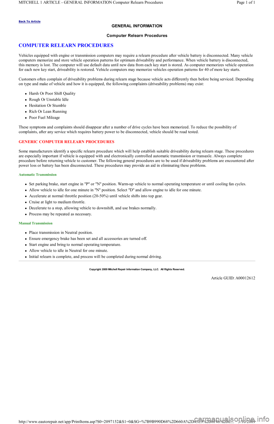
COMPUTER RELEARN PROCEDURES
Vehicles equipped with engine or transmission computers may require a relearn procedure after vehicle battery is disconnected. Many vehicle
computers memorize and store vehicle operation patterns for optimum driveability and performance. When vehicle battery is disconnected,
this memory is lost. The computer will use default data until new data from each key start is stored. As computer memorizes vehicle operation
for each new key start, driveability is restored. Vehicle computers may memorize vehicles operation patterns for 40 of more key starts.
Customers often complain of driveability problems during relearn stage because vehicle acts differently then before being serviced. Depending
on type and make of vehicle and how it is equipped, the following complaints (driveability problems) may exist:
Harsh Or Poor Shift Quality
Rough Or Unstable Idle
Hesitation Or Stumble
Rich Or Lean Running
Poor Fuel Mileage
These symptoms and complaints should disappear after a number of drive cycles have been memorized. To reduce the possibility of
complaints, after any service which requires battery power to be disconnected, vehicle should be road tested.
GENERIC COMPUTER RELEARN PROCEDURES
Some manufacturers identify a specific relearn procedure which will help establish suitable driveability during relearn stage. These procedures
are especially important if vehicle is equipped with and electronically controlled automatic transmission or transaxle. Always complete
procedure before returning vehicle to customer. The following general procedures are to be used if driveability problems are encountered after
power loss or battery has been disconnected. These procedures may provide an aid in eliminating these problems.
Automatic Transmission
Set parking brake, start engine in "P" or "N" position. Warm-up vehicle to normal operating temperature or until cooling fan cycles.
Allow vehicle to idle for one minute in "N" position. Select "D" and allow engine to idle for one minute.
Accelerate at normal throttle position (20-50%) until vehicle shifts into top gear.
Cruise at light to medium throttle.
Decelerate to a stop, allowing vehicle to downshift, and use brakes normally.
Process may be repeated as necessary.
Manual Transmission
Place transmission in Neutral position.
Ensure emergency brake has been set and all accessories are turned off.
Start engine and bring to normal operating temperature.
Allow vehicle to idle in Neutral for one minute.
Initial relearn is complete, and process will be completed during normal driving.
Copyr ight 2009 Mitchell Repair Information Company, LLC. All Rights Reserved.
Article GUID: A00012612
Page 1 of 1 MITCHELL 1 ARTICLE - GENERAL INFORMATION Computer Relearn Procedures
3/10/2009 http://www.eautorepair.net/app/PrintItems.asp?S0=2097152&S1=0&SG=%7B9B990D68%2D660A%2D45E9%2D8F46%2DE
...
Page 253 of 454
Back To Article
GENERAL INFORMATION
Drive Axle Noise Diagnosis
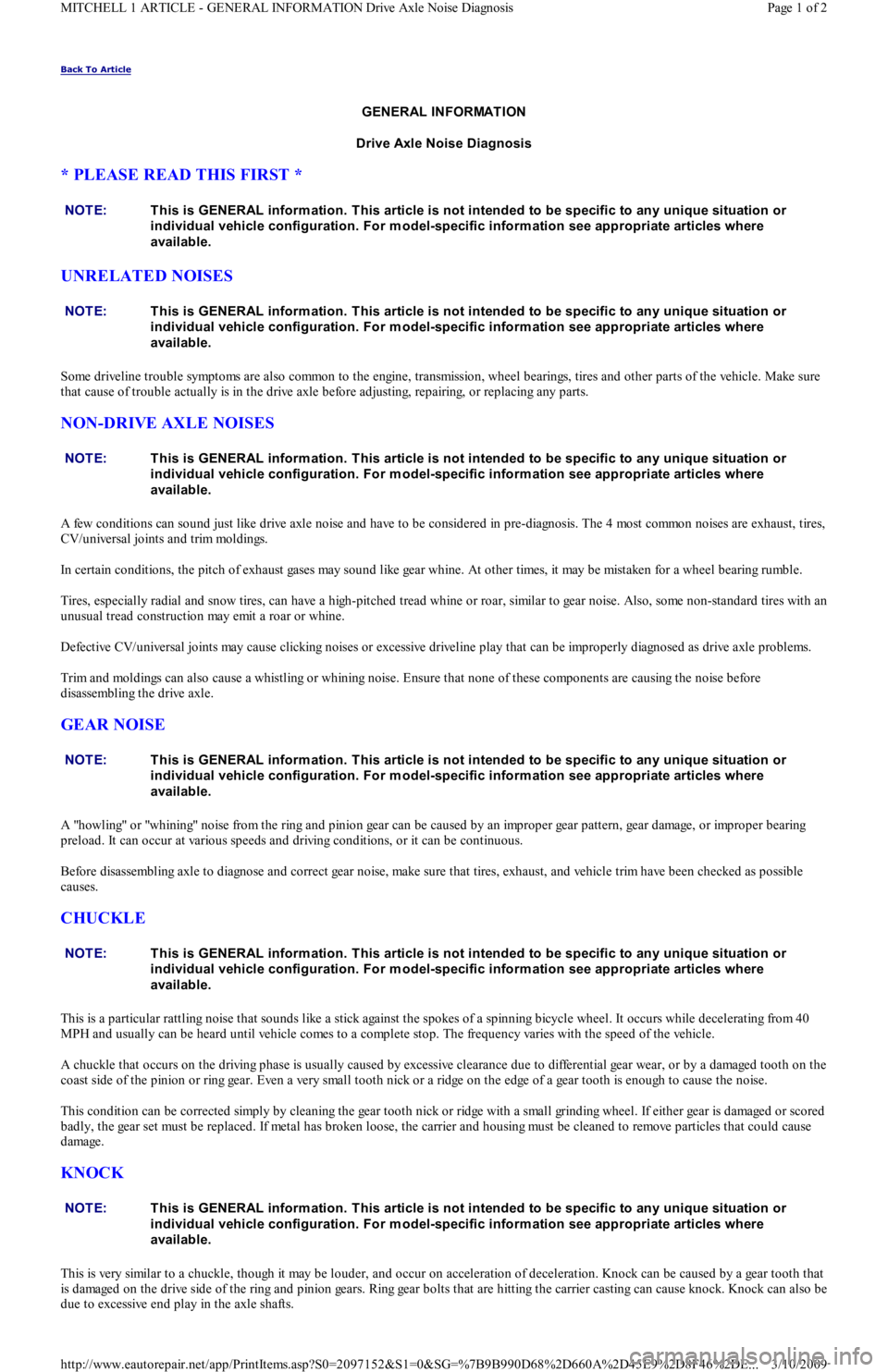
* PLEASE READ THIS FIRST *
UNRELATED NOISES
Some driveline trouble symptoms are also common to the engine, transmission, wheel bearings, tires and other parts of the vehicle. Make sure
that cause of trouble actually is in the drive axle before adjusting, repairing, or replacing any parts.
NON-DRIVE AXLE NOISES
A few conditions can sound just like drive axle noise and have to be considered in pre-diagnosis. The 4 most common noises are exhaust, tires,
CV/universal joints and trim moldings.
In certain conditions, the pitch of exhaust gases may sound like gear whine. At other times, it may be mistaken for a wheel bearing rumble.
Tires, especially radial and snow tires, can have a high-pitched tread whine or roar, similar to gear noise. Also, some non-standard tires with an
unusual tread construction may emit a roar or whine.
Defective CV/universal joints may cause clicking noises or excessive driveline play that can be improperly diagnosed as drive axle problems.
Trim and moldings can also cause a whistling or whining noise. Ensure that none of these components are causing the noise before
disassembling the drive axle.
GEAR NOISE
A "howling" or "whining" noise from the ring and pinion gear can be caused by an improper gear pattern, gear damage, or improper bearing
preload. It can occur at various speeds and driving conditions, or it can be continuous.
Before disassembling axle to diagnose and correct gear noise, make sure that tires, exhaust, and vehicle trim have been checked as possible
causes.
CHUCKLE
This is a particular rattling noise that sounds like a stick against the spokes of a spinning bicycle wheel. It occurs while decelerating from 40
MPH and usually can be heard until vehicle comes to a complete stop. The frequency varies with the speed of the vehicle.
A chuckle that occurs on the driving phase is usually caused by excessive clearance due to differential gear wear, or by a damaged tooth on the
coast side of the pinion or ring gear. Even a very small tooth nick or a ridge on the edge of a gear tooth is enough to cause the noise.
This condition can be corrected simply by cleaning the gear tooth nick or ridge with a small grinding wheel. If either gear is damaged or scored
badly, the gear set must be replaced. If metal has broken loose, the carrier and housing must be cleaned to remove particles that could cause
damage.
KNOCK
This is very similar to a chuckle, though it may be louder, and occur on acceleration of deceleration. Knock can be caused by a gear tooth that
is damaged on the drive side of the ring and pinion gears. Ring gear bolts that are hitting the carrier casting can cause knock. Knock can also be
due to excessive end play in the axle shafts. NOTE:This is GENERAL inform ation. This article is not intended to be specific to any unique situation or
individual vehicle configuration. For m odel-specific inform ation see appropriate articles where
available.
NOTE:This is GENERAL inform ation. This article is not intended to be specific to any unique situation or
individual vehicle configuration. For m odel-specific inform ation see appropriate articles where
available.
NOTE:This is GENERAL inform ation. This article is not intended to be specific to any unique situation or
individual vehicle configuration. For m odel-specific inform ation see appropriate articles where
available.
NOTE:This is GENERAL inform ation. This article is not intended to be specific to any unique situation or
individual vehicle configuration. For m odel-specific inform ation see appropriate articles where
available.
NOTE:This is GENERAL inform ation. This article is not intended to be specific to any unique situation or
individual vehicle configuration. For m odel-specific inform ation see appropriate articles where
available.
NOTE:This is GENERAL inform ation. This article is not intended to be specific to any unique situation or
individual vehicle configuration. For m odel-specific inform ation see appropriate articles where
available.
Page 1 of 2 MITCHELL 1 ARTICLE - GENERAL INFORMATION Drive Axle Noise Diagnosis
3/10/2009 http://www.eautorepair.net/app/PrintItems.asp?S0=2097152&S1=0&SG=%7B9B990D68%2D660A%2D45E9%2D8F46%2DE
...
Page 254 of 454
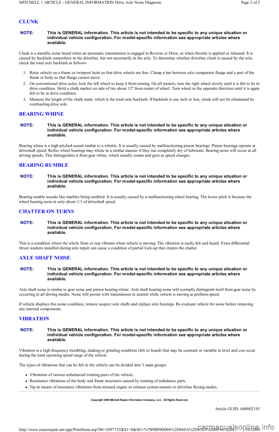
CLUNK
Clunk is a metallic noise heard when an automatic transmission is engaged in Reverse or Drive, or when throttle is applied or released. It is
caused by backlash somewhere in the driveline, but not necessarily in the axle. To determine whether driveline clunk is caused by the axle,
check the total axle backlash as follows:
1. Raise vehicle on a frame or twinpost hoist so that drive wheels are free. Clamp a bar between axle companion flange and a part of the
frame or body so that flange cannot move.
2. On conventional drive axles, lock the left wheel to keep it from turning. On all models, turn the right wheel slowly until it is felt to be in
drive condition. Hold a chalk marker on side of tire about 12" from center of wheel. Turn wheel in the opposite direction until it is again
felt to be in drive condition.
3. Measure the length of the chalk mark, which is the total axle backlash. If backlash is one inch or less, clunk will not be eliminated by
overhauling drive axle.
BEARING WHINE
Bearing whine is a high-pitched sound similar to a whistle. It is usually caused by malfunctioning pinion bearings. Pinion bearings operate at
driveshaft speed. Roller wheel bearings may whine in a similar manner if they run completely dry of lubricant. Bearing noise will occur at all
driving speeds. This distinguishes it from gear whine, which usually comes and goes as speed changes.
BEARING RUMBLE
Bearing rumble sounds like marbles being tumbled. It is usually caused by a malfunctioning wheel bearing. The lower pitch is because the
wheel bearing turns at only about 1/3 of driveshaft speed.
CHATTER ON TURNS
This is a condition where the whole front or rear vibrates when vehicle is moving. The vibration is easily felt and heard. Extra differential
thrust washers installed during axle repair can cause a condition of partial lock-up that creates the chatter.
AXLE SHAFT NOISE
Axle shaft noise is similar to gear noise and pinion bearing whine. Axle shaft bearing noise will normally distinguish itself from gear noise by
occurring in all driving modes. Noise will persist with transmission in neutral while vehicle is moving at problem speed.
If vehicle displays this noise condition, remove suspect axle shafts and replace axle bearings. Re-evaluate vehicle for noise before removing
any internal components.
VIB R AT ION
Vibration is a high-frequency trembling, shaking or grinding condition (felt or heard) that may be constant or variable in level and con occur
during the total operating speed range of the vehicle.
The types of vibrations that can be felt in the vehicle can be divided into 3 main groups:
Vibrations of various unbalanced rotating parts of the vehicle.
Resonance vibrations of the body and frame structures caused by rotating of unbalance parts.
Tip-in moans of resonance vibrations from stressed engine or exhaust system mounts or driveline flexing modes. NOTE:This is GENERAL inform ation. This article is not intended to be specific to any unique situation or
individual vehicle configuration. For m odel-specific inform ation see appropriate articles where
available.
NOTE:This is GENERAL inform ation. This article is not intended to be specific to any unique situation or
individual vehicle configuration. For m odel-specific inform ation see appropriate articles where
available.
NOTE:This is GENERAL inform ation. This article is not intended to be specific to any unique situation or
individual vehicle configuration. For m odel-specific inform ation see appropriate articles where
available.
NOTE:This is GENERAL inform ation. This article is not intended to be specific to any unique situation or
individual vehicle configuration. For m odel-specific inform ation see appropriate articles where
available.
NOTE:This is GENERAL inform ation. This article is not intended to be specific to any unique situation or
individual vehicle configuration. For m odel-specific inform ation see appropriate articles where
available.
NOTE:This is GENERAL inform ation. This article is not intended to be specific to any unique situation or
individual vehicle configuration. For m odel-specific inform ation see appropriate articles where
available.
Copyr ight 2009 Mitchell Repair Information Company, LLC. All Rights Reserved.
Article GUID: A00002193
Page 2 of 2 MITCHELL 1 ARTICLE - GENERAL INFORMATION Drive Axle Noise Diagnosis
3/10/2009 http://www.eautorepair.net/app/PrintItems.asp?S0=2097152&S1=0&SG=%7B9B990D68%2D660A%2D45E9%2D8F46%2DE
...
Page 255 of 454
Back To Article
GENERAL INFORMATION
Gear T ooth Contact Patterns
* PLEASE READ THIS FIRST *
INSPECTION
Wipe lubricant from internal parts. Rotate gears and inspect for wear or damage. Mount dial indicator to housing and check backlash at several
points around ring gear. Backlash must be within specification at all points. If no defects are found, check gear tooth pattern contact.
GEAR TOOTH CONTACT PATTERN
1. Paint ring gear teeth with marking compound. Wrap cloth or rope around drive pinion flange to act as brake. Rotate gear until clear
contact pattern is obtained.
2. Contact pattern will indicate whether correct pinion bearing mounting shim has been installed and if drive gear backlash has been set
properly. Backlash between drive gear pinion must be maintained within specified limits until correct tooth pattern is obtained.
ADJUSTMENTS
GEAR BACKLASH & PINION SHIM CHANGES
1. With no change in backlash, moving pinion further from ring gear moves drive pattern toward heel and top of tooth, and moves coast
pattern toward toe and top of tooth.
2. With no change in backlash, moving pinion closer to ring gear moves drive pattern toward toe and bottom of tooth, and moves coast
pattern toward heel and bottom of tooth.
3. With no change in pinion shim thickness, an increase in backlash moves ring gear further from pinion. Both drive and coast patterns
move toward heel and top of tooth.
4. With no change in pinion shim thickness, a decrease in backlash moves ring gear closer to pinion gear. Both drive and coast patterns
move toward toe and bottom of tooth. NOTE:This is GENERAL inform ation. This article is not intended to be specific to any unique situation or
individual vehicle configuration. For m odel-specific inform ation see appropriate articles where
available.
NOTE:This is GENERAL inform ation. This article is not intended to be specific to any unique situation or
individual vehicle configuration. For m odel-specific inform ation see appropriate articles where
available.
NOTE:Drive pattern should be well centered on ring gear teeth. Coast pattern should be centered, but m ay be
slightly toward toe of ring gear teeth.
NOTE:This is GENERAL inform ation. This article is not intended to be specific to any unique situation or
individual vehicle configuration. For m odel-specific inform ation see appropriate articles where
available.
NOTE:This is GENERAL inform ation. This article is not intended to be specific to any unique situation or
individual vehicle configuration. For m odel-specific inform ation see appropriate articles where
available.
NOTE:This is GENERAL inform ation. This article is not intended to be specific to any unique situation or
individual vehicle configuration. For m odel-specific inform ation see appropriate articles where
available.
Page 1 of 2 MITCHELL 1 ARTICLE - GENERAL INFORMATION Gear Tooth Contact Patterns
3/10/2009 http://www.eautorepair.net/app/PrintItems.asp?S0=2097152&S1=0&SG=%7B9B990D68%2D660A%2D45E9%2D8F46%2DE
...
Page 256 of 454
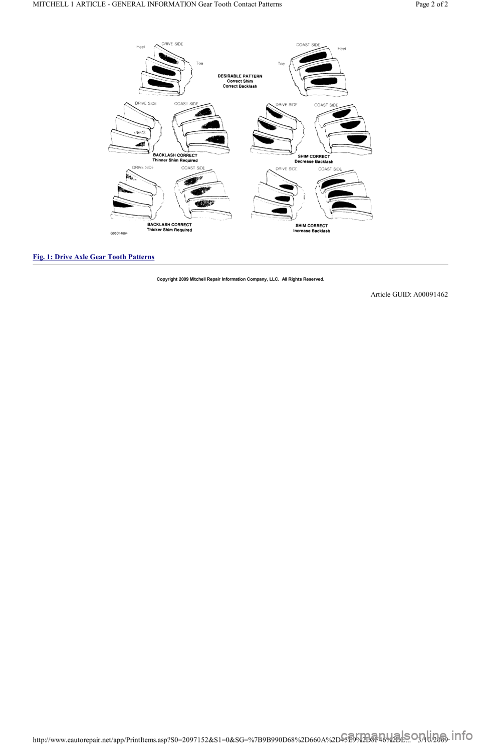
Fig. 1: Drive Axle Gear Tooth Patterns
Copyr ight 2009 Mitchell Repair Information Company, LLC. All Rights Reserved.
Article GUID: A00091462
Page 2 of 2 MITCHELL 1 ARTICLE - GENERAL INFORMATION Gear Tooth Contact Patterns
3/10/2009 http://www.eautorepair.net/app/PrintItems.asp?S0=2097152&S1=0&SG=%7B9B990D68%2D660A%2D45E9%2D8F46%2DE
...
Page 257 of 454
Back To Article
GENERAL INFORMATION
Clutch Trouble Shooting
* PLEASE READ THIS FIRST *
ALL MODELS
CLUTCH TROUBLE SHOOTING NOTE:This is GENERAL inform ation. This article is not intended to be specific to any unique situation or
individual vehicle configuration. For m odel-specific inform ation see appropriate articles where
available.
NOTE:This is GENERAL inform ation. This article is not intended to be specific to any unique situation or
individual vehicle configuration. For m odel-specific inform ation see appropriate articles where
available.
Problem & Possible CauseAction
Clutch Chatters/Grabs
Incorrect Pedal AdjustmentAdjust Free Play
Worn Input Shaft SplineReplace Input Shaft
Binding Pressure PlateReplace Pressure Plate
Binding Throw-Out LeverCheck Throw-Out Lever,
Check Throw-Out
Bearing, Check Bearing
Retainer
Uneven Pressure Plate Contact With FlywheelAlign/Replace Worn Parts
Transmission MisalignedAlign Transmission
Worn Pressure PlateReplace Clutch Assembly
Oil-Saturated DiscReplace Clutch Assembly,
Repair Oil Leak
Loose Engine MountsReplace Engine Mounts
Clutch Pedal Sticks Down
Clutch Cable BindingReplace Clutch Cable
Weak Pressure Plate SpringsReplace Clutch Assembly
Binding Clutch LinkageLubricate Linkage
Broken Clutch Pedal Return SpringReplace Return Spring
Clutch Will Not Release
Oil-Saturated DiscReplace Clutch Assembly,
Repair Oil Leak
Defective Disc FaceReplace Clutch Assembly
Disc Sticking on Input Shaft SplinesReplace Disc/Input Shaft
Binding Pilot BearingReplace Pilot Bearing
Faulty Clutch Master CylinderReplace Master Cylinder
Faulty Clutch Slave CylinderReplace Slave Cylinder
Blown Clutch HoseReplace Hose
Sticky Throw-Out Bearing SleeveClean/Lube Sleeve
Clutch Cable BindingReplace Clutch Cable
Broken/Loose BellhousingCheck Bellhousing
Rattling/Squeaking
Broken Throw-Out Lever Return SpringReplace Return Spring
Faulty Throw-Out BearingReplace Throw-Out
Bearing
Faulty Clutch DiscReplace Clutch Disc
Faulty Pilot BearingReplace Pilot Bearing
Worn Throw-Out BearingReplace Throw-Out
Bearing
Dry Bearing Retainer Slide For Throw-Out Bearing SleeveLubricate Slide
Slipping
Faulty Pressure PlateReplace Clutch Assembly
Worn Clutch DiscReplace Clutch Assembly
Incorrect AlignmentRealign Clutch Assembly
Faulty Clutch Slave CylinderReplace Slave Cylinder
No Pedal Pressure
Leaky Hydraulic SystemCheck Clutch Master
Cylinder, Check Clutch
Slave Cylinder
Check Clutch Hose
Broken Clutch CableReplace Clutch Cable
Faulty Throw-Out LeverReplace Throw-Out Lever
Broken Clutch LinkageRepair Clutch Linkage
Page 1 of 2 MITCHELL 1 ARTICLE - GENERAL INFORMATION Clutch Trouble Shooting
3/10/2009 http://www.eautorepair.net/app/PrintItems.asp?S0=2097152&S1=0&SG=%7B9B990D68%2D660A%2D45E9%2D8F46%2DE
...
Page 258 of 454
Noisy Clutch Pedal
Faulty Safety SwitchCheck/Replace Switch
Noisy Self-Adj. RatchetReplace Ratchet
Dry Throw-Out BearingReplace Throw-Out
Bearing
Dry Pilot BearingReplace Pilot Bearing
Worn Input ShaftReplace Input Shaft
Copyr ight 2009 Mitchell Repair Information Company, LLC. All Rights Reserved.
Article GUID: A00091461
Page 2 of 2 MITCHELL 1 ARTICLE - GENERAL INFORMATION Clutch Trouble Shooting
3/10/2009 http://www.eautorepair.net/app/PrintItems.asp?S0=2097152&S1=0&SG=%7B9B990D68%2D660A%2D45E9%2D8F46%2DE
...
Page 259 of 454
Back To Article
GENERAL INFORMATION
Electrostatic Discharge (ESD) Warning - Basic Inform ation
* PLEASE READ THIS FIRST *
INTRODUCTION
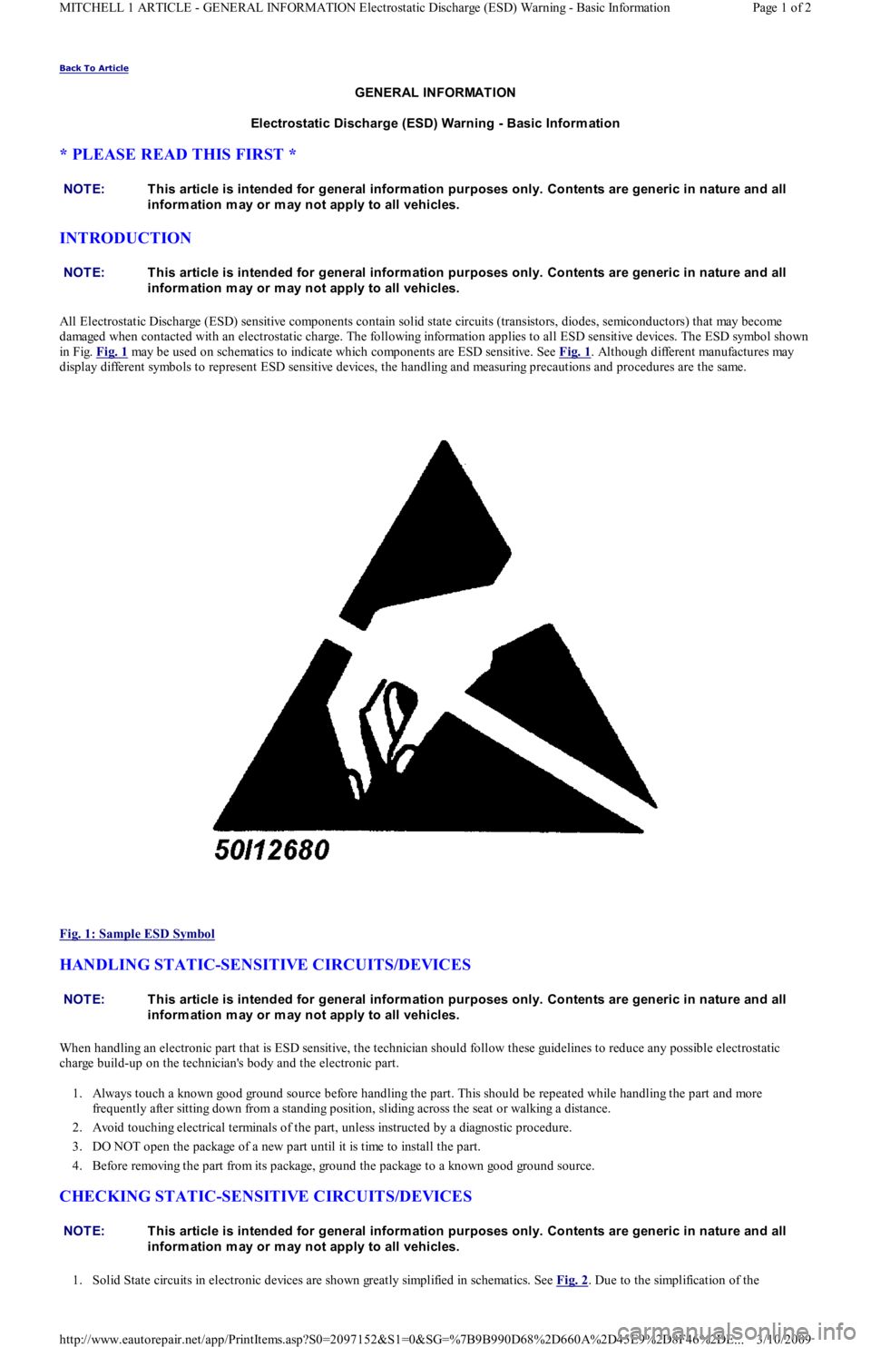
All Electrostatic Discharge (ESD) sensitive components contain solid state circuits (transistors, diodes, semiconductors) that may become
damaged when contacted with an electrostatic charge. The following information applies to all ESD sensitive devices. The ESD symbol shown
in Fig. Fig. 1
may be used on schematics to indicate which components are ESD sensitive. See Fig. 1. Although different manufactures may
display different symbols to represent ESD sensitive devices, the handling and measuring precautions and procedures are the same.
Fig. 1: Sample ESD Symbol
HANDLING STATIC-SENSITIVE CIRCUITS/DEVICES
When handling an electronic part that is ESD sensitive, the technician should follow these guidelines to reduce any possible electrostatic
charge build-up on the technician's body and the electronic part.
1. Always touch a known good ground source before handling the part. This should be repeated while handling the part and more
frequently after sitting down from a standing position, sliding across the seat or walking a distance.
2. Avoid touching electrical terminals of the part, unless instructed by a diagnostic procedure.
3. DO NOT open the package of a new part until it is time to install the part.
4. Before removing the part from its package, ground the package to a known good ground source.
CHECKING STATIC-SENSITIVE CIRCUITS/DEVICES
1. Solid State circuits in electronic devices are shown greatly simplified in schematics. See Fig. 2. Due to the simplification of the NOTE:T his article is intended for general inform ation purposes only. Contents are generic in nature and all
inform ation m ay or m ay not apply to all vehicles.
NOTE:T his article is intended for general inform ation purposes only. Contents are generic in nature and all
inform ation m ay or m ay not apply to all vehicles.
NOTE:T his article is intended for general inform ation purposes only. Contents are generic in nature and all
inform ation m ay or m ay not apply to all vehicles.
NOTE:T his article is intended for general inform ation purposes only. Contents are generic in nature and all
inform ation m ay or m ay not apply to all vehicles.
Page 1 of 2 MITCHELL 1 ARTICLE - GENERAL INFORMATION Electrostatic Discharge (ESD) Warning - Basic Information
3/10/2009 http://www.eautorepair.net/app/PrintItems.asp?S0=2097152&S1=0&SG=%7B9B990D68%2D660A%2D45E9%2D8F46%2DE
...
Page 260 of 454
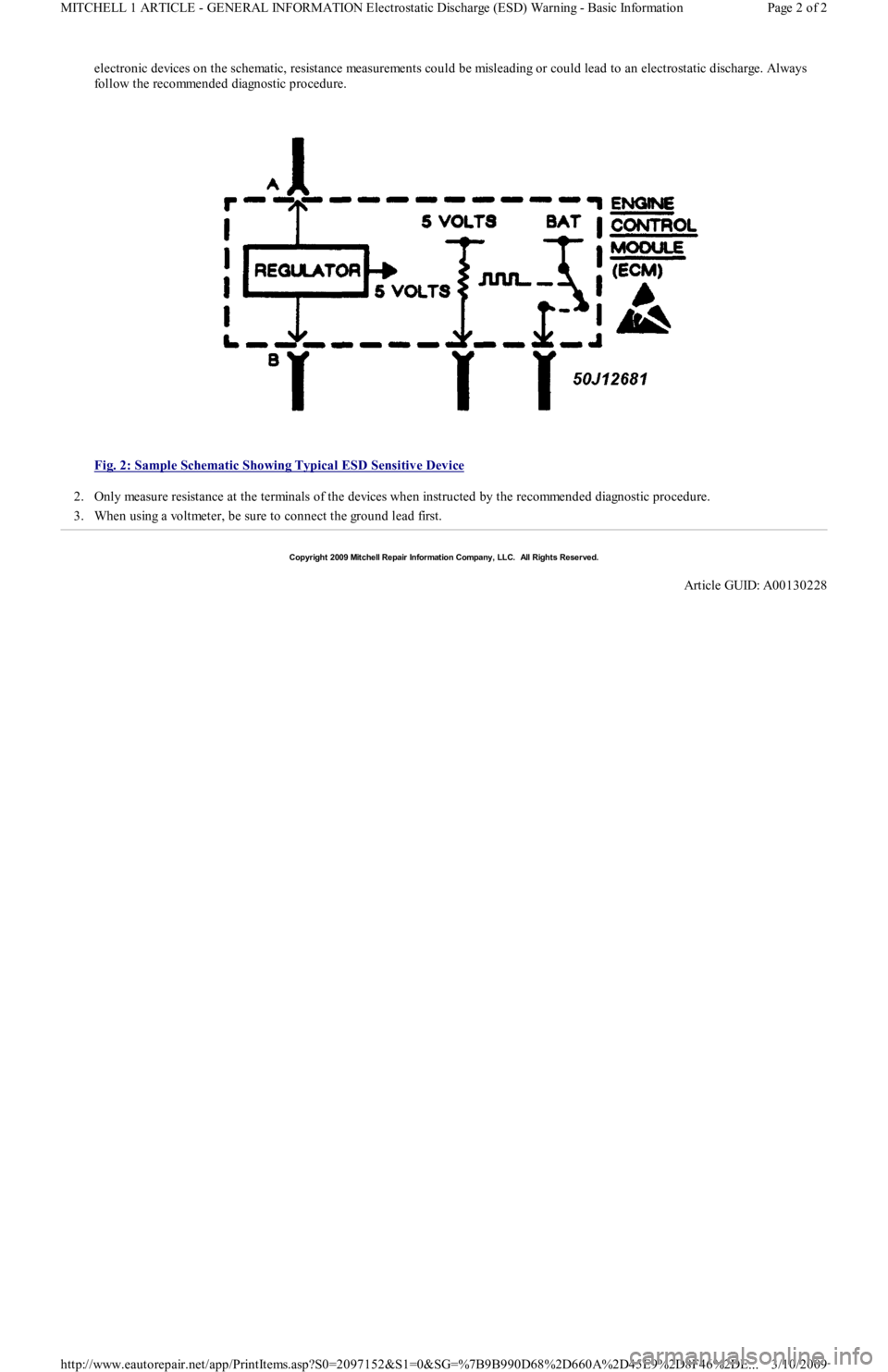
electronic devices on the schematic, resistance measurements could be misleading or could lead to an electrostatic discharge. Always
follow the recommended diagnostic procedure.
Fig. 2: Sample Schematic Showing Typical ESD Sensitive Device
2. Only measure resistance at the terminals of the devices when instructed by the recommended diagnostic procedure.
3. When using a voltmeter, be sure to connect the ground lead first.
Copyr ight 2009 Mitchell Repair Information Company, LLC. All Rights Reserved.
Article GUID: A00130228
Page 2 of 2 MITCHELL 1 ARTICLE - GENERAL INFORMATION Electrostatic Discharge (ESD) Warning - Basic Information
3/10/2009 http://www.eautorepair.net/app/PrintItems.asp?S0=2097152&S1=0&SG=%7B9B990D68%2D660A%2D45E9%2D8F46%2DE
...