FORD FESTIVA 1991 Service Manual
Manufacturer: FORD, Model Year: 1991, Model line: FESTIVA, Model: FORD FESTIVA 1991Pages: 454, PDF Size: 9.53 MB
Page 441 of 454
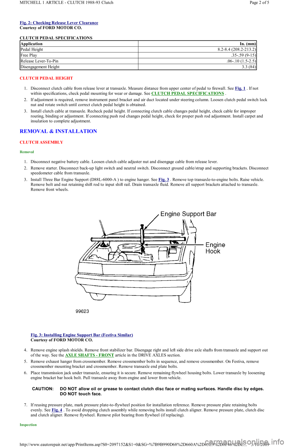
Fig. 2: Checking Release Lever Clearance
Courtesy of FORD MOTOR CO.
CLUTCH PEDAL SPECIFICATIONS
CLUTCH PEDAL HEIGHT
1. Disconnect clutch cable from release lever at transaxle. Measure distance from upper center of pedal to firewall. See Fig. 1
. If not
within specifications, check pedal mounting for wear or damage. See CLUTCH PEDAL SPECIFICATIONS
.
2. If adjustment is required, remove instrument panel bracket and air duct located under steering column. Loosen clutch pedal switch lock
nut and rotate switch until correct clutch pedal height is obtained.
3. Install clutch cable at transaxle. Recheck pedal height. If connecting clutch cable changes pedal height, check cable for improper
routing, binding or adjustment. If connecting push rod changes pedal height, check for proper push rod adjustment. Install carpet and
insulation to complete adjustment.
REMOVAL & INSTALLATION
CLUTCH ASSEMBLY
Removal
1. Disconnect negative battery cable. Loosen clutch cable adjuster nut and disengage cable from release lever.
2. Remove starter. Disconnect back-up light switch and neutral switch. Disconnect ground cable/strap and supporting brackets. Disconnect
speedometer cable from transaxle.
3. Install Three Bar Engine Support (D88L-6000-A ) to engine hanger. See Fig. 3
. Remove top transaxle-to-engine bolts. Raise vehicle.
Remove bolt and nut retaining shift rod to input shift rail. Drain transaxle fluid. Remove all support brackets attached to transaxle.
Remove front wheels.
Fig. 3: Installing Engine Support Bar (Festiva Similar)
Courtesy of FORD MOTOR CO.
4. Remove engine splash shields. Remove front stabilizer bar. Disengage right and left side drive axle shafts from transaxle and support out
of the way. See the AXLE SHAFTS
- FRONT article in the DRIVE AXLES section.
5. Remove exhaust hanger from crossmember. Remove crossmember bolts in sequence, and remove crossmember. On Festiva, remove
crossmember mounting bracket and crossmember. Remove transaxle end plate bolts.
6. Place transmission jack under transaxle, ensuring it is secure. Remove remaining flywheel housing bolts. Lower transaxle by loosening
engine bracket bar hook bolt. Pull transaxle away from engine and lower from vehicle.
7. If reusing pressure plate, mark pressure plate-to-flywheel position for installation reference. Remove pressure plate retaining bolts
evenly. See Fig. 4
. To avoid dropping clutch assembly while removing bolts install clutch aligner. Remove pressure plate, clutch disc
and clutch aligner. Remove flywheel. Remove pilot bearing from flywheel (if replacing).
Inspection
ApplicationIn. (mm)
Pedal Height8.2-8.4 (208.2-213.2)
Free Play.35-.59 (9-15)
Release Lever-To-Pin.06-.10 (1.5-2.5)
Disengagement Height3.3 (84)
CAUT ION: DO NOT allow oil or grease to contact clutch disc face or m ating surfaces. Handle disc by edges.
DO NOT touch face.
Page 2 of 5 MITCHELL 1 ARTICLE - CLUTCH 1988-93 Clutch
3/10/2009 http://www.eautorepair.net/app/PrintItems.asp?S0=2097152&S1=0&SG=%7B9B990D68%2D660A%2D45E9%2D8F46%2DE
...
Page 442 of 454
1. Check pressure plate surfaces for scoring, cracks or discoloration. Remove minor scratches or discoloration with fine emery cloth. Check
pressure plate diaphragm spring fingers for discoloration, scoring, broken or bent segments. Ensure all spring ends are the same height.
2. Check clutch disc lining surface for hardening or presence of oil. Check for worn clutch disc lining. Check for loose lining rivets.
Measure depth of rivet heads. Minimum allowable rivet depth is .012" (0.3 mm). Check for wear or rust on splines. Rust may be
removed with emery cloth.
3. Check flywheel surface for marks, scoring or discoloration. Minor surface repairs may be removed with fine emery cloth. Flywheel must
be machined if scoring, runout, or discoloration is excessive. Maximum flywheel runout is .008" (0.2 mm). Check for damaged or worn
ring gear teeth.
4. Check pilot bearing for wear. Check clutch release/throw out bearing for damage or wear at contact points. Rotate bearing in both
directions and check for binding or abnormal noise.
Installation
1. Replace release bearing and/or pilot bearing as necessary. Clean sealant from flywheel attaching bolt threads. Replace bolts if sealant
cannot be removed. Coat bolt threads with Stud/Bearing Mount Sealer (EOAZ-19554-B ), and install flywheel. Tighten bolts in a
diagonal sequence to specification. See TORQUE SPECIFICATIONS
at the end of this article.
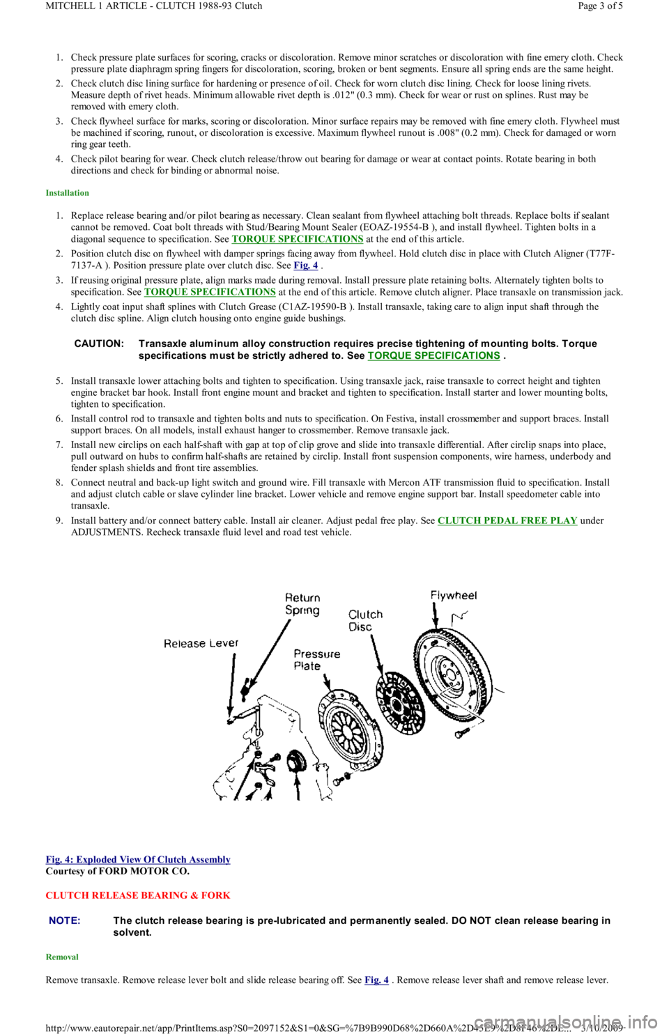
2. Position clutch disc on flywheel with damper springs facing away from flywheel. Hold clutch disc in place with Clutch Aligner (T77F-
7137-A ). Position pressure plate over clutch disc. See Fig. 4
.
3. If reusing original pressure plate, align marks made during removal. Install pressure plate retaining bolts. Alternately tighten bolts to
specification. See TORQUE SPECIFICATIONS
at the end of this article. Remove clutch aligner. Place transaxle on transmission jack.
4. Lightly coat input shaft splines with Clutch Grease (C1AZ-19590-B ). Install transaxle, taking care to align input shaft through the
clutch disc spline. Align clutch housing onto engine guide bushings.
5. Install transaxle lower attaching bolts and tighten to specification. Using transaxle jack, raise transaxle to correct height and tighten
engine bracket bar hook. Install front engine mount and bracket and tighten to specification. Install starter and lower mounting b o l t s,
tighten to specification.
6. Install control rod to transaxle and tighten bolts and nuts to specification. On Festiva, install crossmember and support braces. Install
support braces. On all models, install exhaust hanger to crossmember. Remove transaxle jack.
7. Install new circlips on each half-shaft with gap at top of clip grove and slide into transaxle differential. After circlip snaps into place,
pull outward on hubs to confirm half-shafts are retained by circlip. Install front suspension components, wire harness, underbody and
fender splash shields and front tire assemblies.
8. Connect neutral and back-up light switch and ground wire. Fill transaxle with Mercon ATF transmission fluid to specification. In st al l
and adjust clutch cable or slave cylinder line bracket. Lower vehicle and remove engine support bar. Install speedometer cable into
transaxle.
9. Install battery and/or connect battery cable. Install air cleaner. Adjust pedal free play. See CLUTCH PEDAL FREE PLAY
under
ADJUSTMENTS. Recheck transaxle fluid level and road test vehicle.
Fig. 4: Exploded View Of Clutch Assembly
Courtesy of FORD MOTOR CO.
CLUTCH RELEASE BEARING & FORK
Removal
Remove transaxle. Remove release lever bolt and slide release bearing off. See Fig. 4 . Remove release lever shaft and remove release lever. CAUT ION: T ransaxle alum inum alloy construction requires precise tightening of m ounting bolts. T orque
specifications m ust be strictly adhered to. See T ORQUE SPECIFICAT IONS
.
NOTE:T he clutch release bearing is pre-lubricated and perm anently sealed. DO NOT clean release bearing in
solvent.
Page 3 of 5 MITCHELL 1 ARTICLE - CLUTCH 1988-93 Clutch
3/10/2009 http://www.eautorepair.net/app/PrintItems.asp?S0=2097152&S1=0&SG=%7B9B990D68%2D660A%2D45E9%2D8F46%2DE
...
Page 443 of 454
Inspection
Check release bearing rotation operation for roughness, sticking and noise. Check release lever and transaxle front bearing retainer for wear or
damage. Ensure bearing slides smoothly on transaxle input shaft. Check release lever shaft for bent, worn or damaged condition. Check all
mating surfaces for wear or damage. Replace worn or defective components.
Installation
Apply light film of grease to transmission front bearing retainer lever-to-bearing surfaces and release lever contact surface. Align bolt hole in
release lever and shaft. Apply Stud/Bearing Sealant (E0AZ-19554-B ) to release lever bolt. Fill grease groove in release bearing hub and
remove any excess grease. Install release lever return spring. To complete installation, reverse removal procedure.
PILOT BEARING
Removal & Installation
Remove transaxle, pressure plate, clutch disc and flywheel. Drive pilot bearing out of flywheel using a driver that makes full contact with
bearing outer race. Reverse procedure for installation.
CLUTCH CABLE
Removal & Installation
1. Disconnect clutch cable from release lever. Remove nuts retaining clutch cable at firewall. Unhook clutch cable at clutch pedal.
2. Remove clutch cable from engine compartment side. To install, apply lithium grease to pedal cable hook and joint between release lever
and pin. Reverse removal procedure to complete installation. See Fig. 2
.
OVERHAUL
TORQUE SPECIFICATIONS
TORQUE SPECIFICATIONS
TRANSAXLE FLUID LEVELS
TRANSAXLE FLUID LEVELS NOTE:DO NOT rem ove pilot bearing unless necessary.
NOTE:Manufacturer does not provide overhaul inform ation for clutch m aster cylinder and clutch release
cylinder.
ApplicationFt. Lbs. (Nm)
Clutch Cable Bracket Nuts12-17 (16-23)
Clutch Pedal Push Rod Lock Nut9-13 (12-17)
Clutch Pedal Through Bolt Nut15-26 (20-35)
Crossmember
"A" Bo l t s47-66 (64-89)
"B" Bo l t21-34 (28-46)
Crossmember Brace (Front)23-34 (31-46)
Crossmember Brace69-86 (93-117)
Engine Mount Bolt (No. 2)33-48 (45-65)
Engine-To-Transaxle46-66 (63-89)
Flywheel Housing-To-Engine Bolt46-66 (63-89)
Flywheel-To-Crankshaft Bolt71-76 (96-103)
Front Wheel Lug Nut66-89 (90-120)
Lower Ball Joint Pinch Bolt32-40 (43-54)
Master Cylinder Retaining Nuts14-19 (19-26)
Pressure Plate-To-Flywheel Bolt13-20 (18-27)
Rear Engine Cover-To-Housing Bolt28-38 (38-51)
Rear Mount-To-Transmission Bolt50-70 (68-95)
Rear Transmission Mount-To-Body Bolt25-35 (34-48)
Release Fork Attaching Bolt26-30 (35-41)
Slave Cylinder Retaining Bolts12-17 (16-23)
Stabilizer Bracket-To-Body Bolt33-41 (45-56)
Starter Motor-To-Mount Bolt23-34 (31-46)
Transaxle Drain Plug29-40 (39-54)
INCH Lbs. (N.m)
Release Lever Bolt71-97 (8-11)
Speedometer Drive Gear Bolt69-106 (7.8-12)
ApplicationSpecification
Festiva2.6 Qts. (2.5L)
Copyr ight 2009 Mitchell Repair Information Company, LLC. All Rights Reserved.
Page 4 of 5 MITCHELL 1 ARTICLE - CLUTCH 1988-93 Clutch
3/10/2009 http://www.eautorepair.net/app/PrintItems.asp?S0=2097152&S1=0&SG=%7B9B990D68%2D660A%2D45E9%2D8F46%2DE
...
Page 444 of 454
Article GUID: A00043399
Page 5 of 5 MITCHELL 1 ARTICLE - CLUTCH 1988-93 Clutch
3/10/2009 http://www.eautorepair.net/app/PrintItems.asp?S0=2097152&S1=0&SG=%7B9B990D68%2D660A%2D45E9%2D8F46%2DE
...
Page 445 of 454
Back To Article
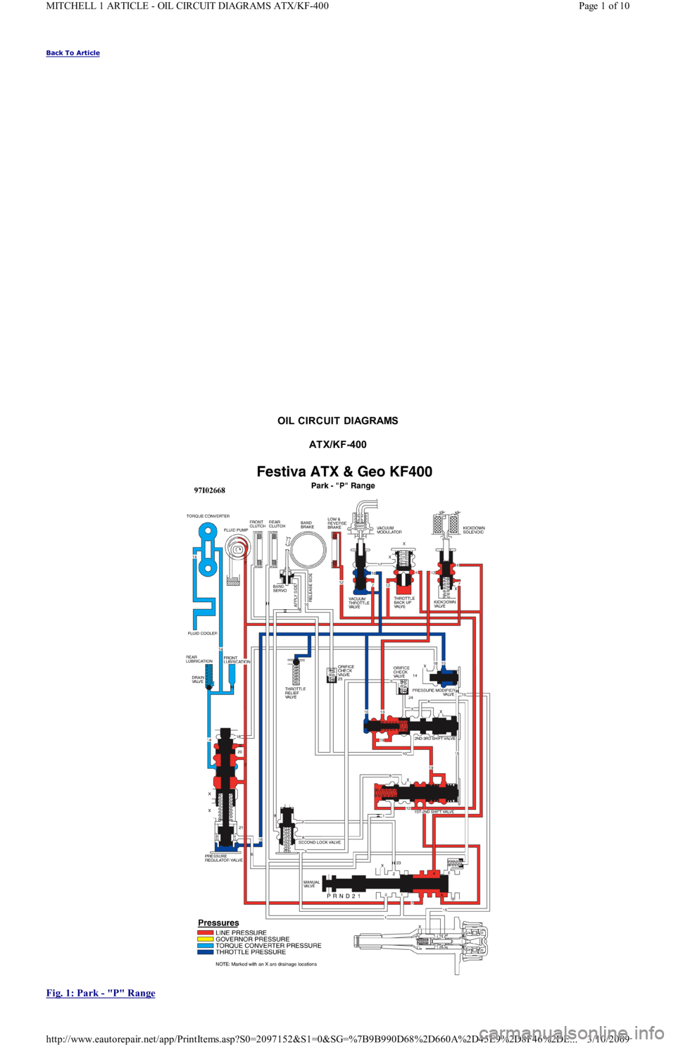
OIL CIRCUIT DIAGRAMS
AT X/KF-400
Fig. 1: Park
- "P" Range
Page 1 of 10 MITCHELL 1 ARTICLE - OIL CIRCUIT DIAGRAMS ATX/KF-400
3/10/2009 http://www.eautorepair.net/app/PrintItems.asp?S0=2097152&S1=0&SG=%7B9B990D68%2D660A%2D45E9%2D8F46%2DE
...
Page 446 of 454
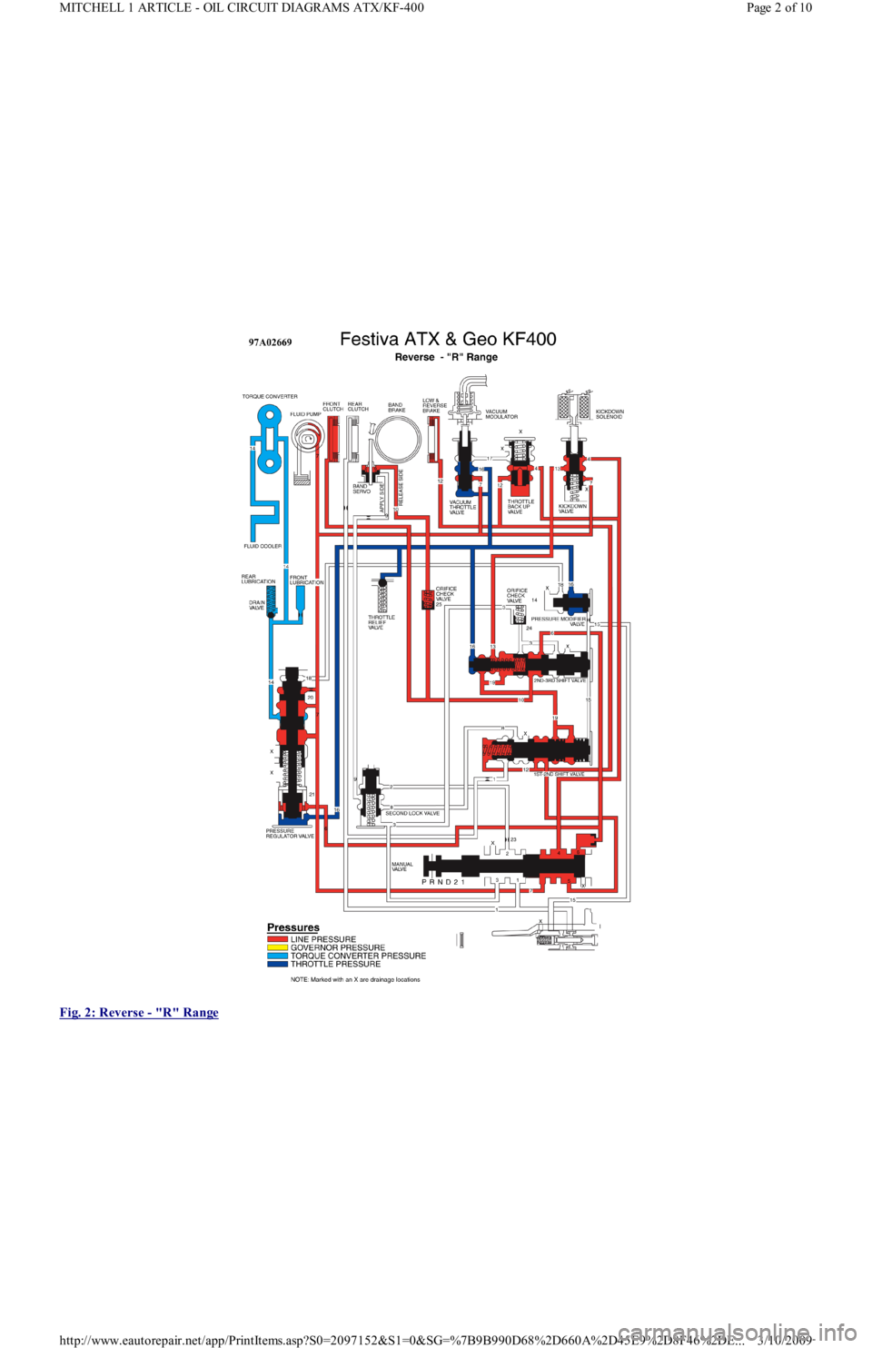
Fig. 2: Reverse
- "R" Range
Page 2 of 10 MITCHELL 1 ARTICLE - OIL CIRCUIT DIAGRAMS ATX/KF-400
3/10/2009 http://www.eautorepair.net/app/PrintItems.asp?S0=2097152&S1=0&SG=%7B9B990D68%2D660A%2D45E9%2D8F46%2DE
...
Page 447 of 454
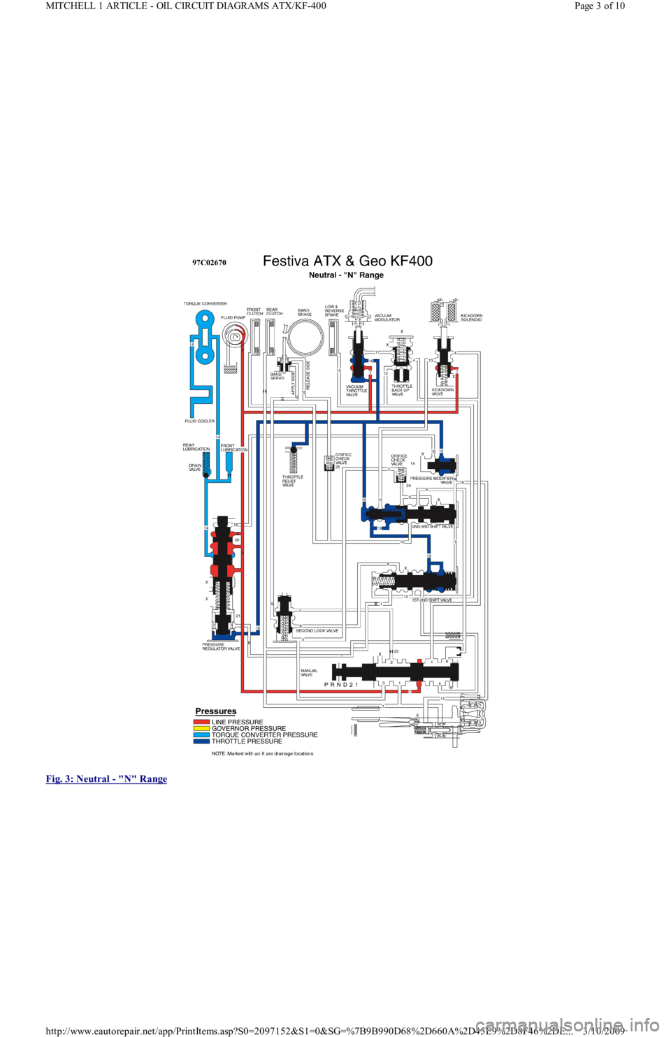
Fig. 3: Neutral
- "N" Range
Page 3 of 10 MITCHELL 1 ARTICLE - OIL CIRCUIT DIAGRAMS ATX/KF-400
3/10/2009 http://www.eautorepair.net/app/PrintItems.asp?S0=2097152&S1=0&SG=%7B9B990D68%2D660A%2D45E9%2D8F46%2DE
...
Page 448 of 454
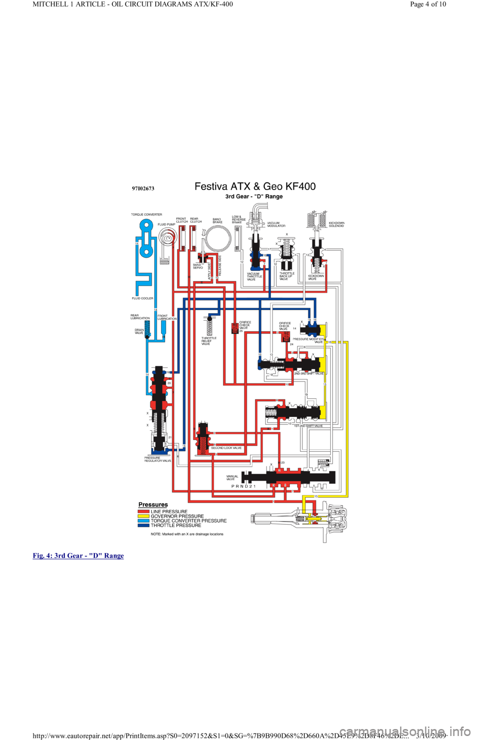
Fig. 4: 3rd Gear
- "D" Range
Page 4 of 10 MITCHELL 1 ARTICLE - OIL CIRCUIT DIAGRAMS ATX/KF-400
3/10/2009 http://www.eautorepair.net/app/PrintItems.asp?S0=2097152&S1=0&SG=%7B9B990D68%2D660A%2D45E9%2D8F46%2DE
...
Page 449 of 454
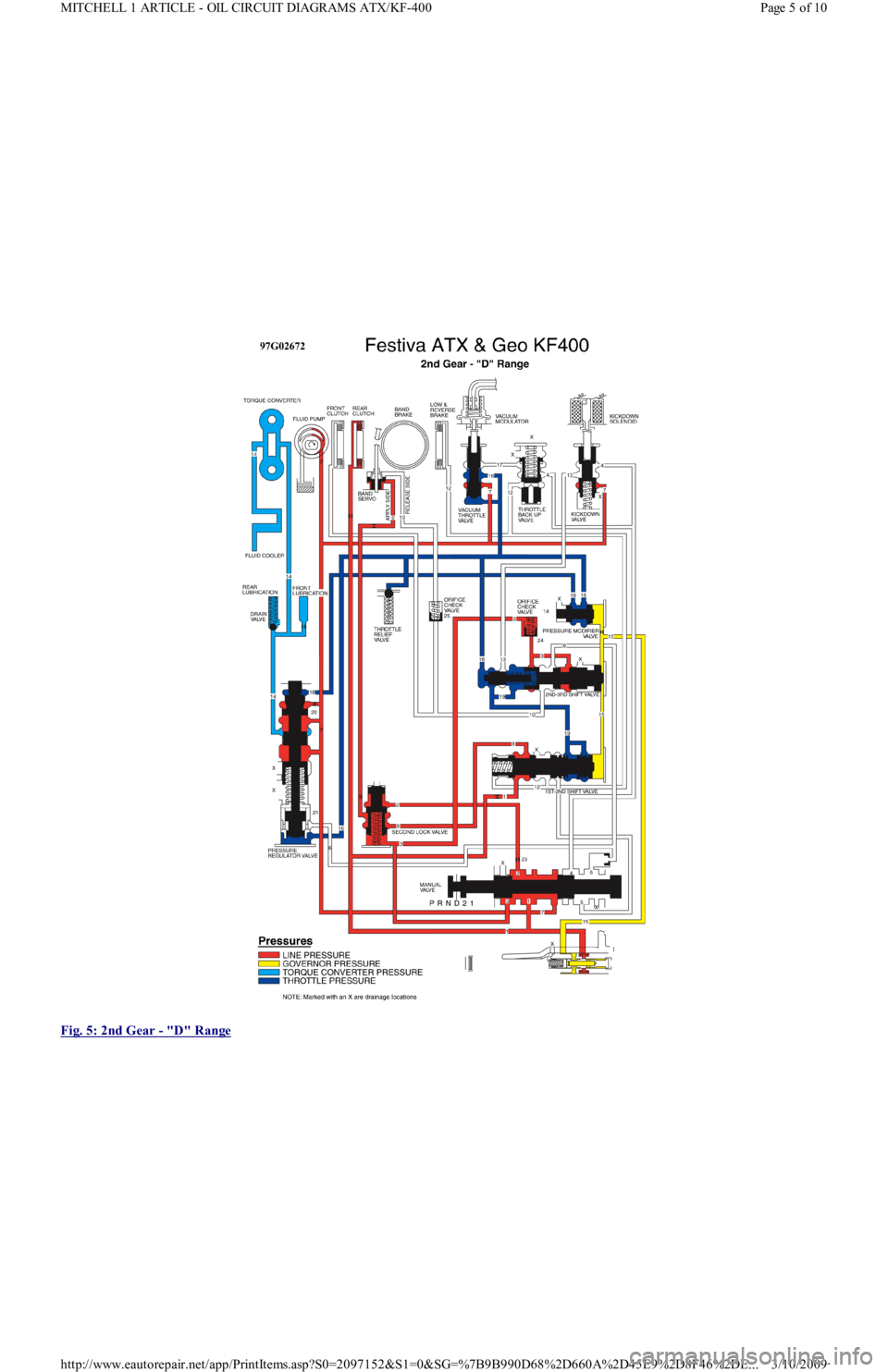
Fig. 5: 2nd Gear
- "D" Range
Page 5 of 10 MITCHELL 1 ARTICLE - OIL CIRCUIT DIAGRAMS ATX/KF-400
3/10/2009 http://www.eautorepair.net/app/PrintItems.asp?S0=2097152&S1=0&SG=%7B9B990D68%2D660A%2D45E9%2D8F46%2DE
...
Page 450 of 454
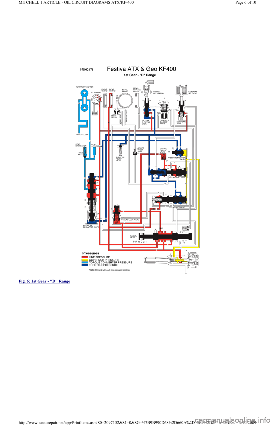
Fig. 6: 1st Gear
- "D" Range
Page 6 of 10 MITCHELL 1 ARTICLE - OIL CIRCUIT DIAGRAMS ATX/KF-400
3/10/2009 http://www.eautorepair.net/app/PrintItems.asp?S0=2097152&S1=0&SG=%7B9B990D68%2D660A%2D45E9%2D8F46%2DE
...