FORD FESTIVA 1991 Service Manual
Manufacturer: FORD, Model Year: 1991, Model line: FESTIVA, Model: FORD FESTIVA 1991Pages: 454, PDF Size: 9.53 MB
Page 431 of 454
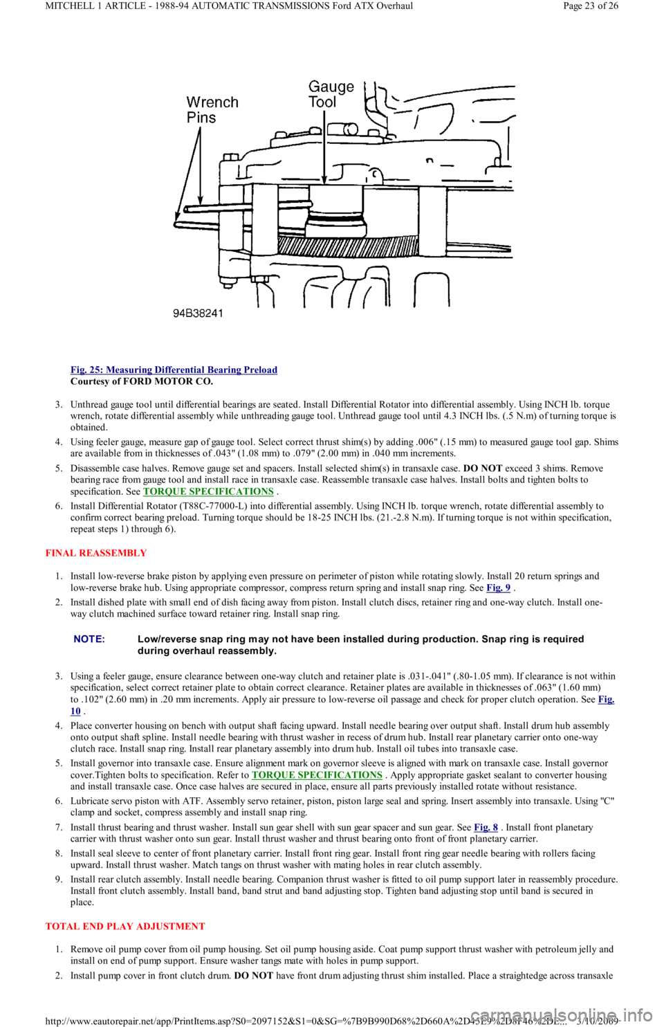
Fig. 25: Measuring Differential Bearing Preload
Courtesy of FORD MOTOR CO.
3. Unthread gauge tool until differential bearings are seated. Install Differential Rotator into differential assembly. Using INCH lb. torque
wrench, rotate differential assembly while unthreading gauge tool. Unthread gauge tool until 4.3 INCH lbs. (.5 N.m) of turning torque is
obtained.
4. Using feeler gauge, measure gap of gauge tool. Select correct thrust shim(s) by adding .006" (.15 mm) to measured gauge tool ga p . S h ims
are available from in thicknesses of .043" (1.08 mm) to .079" (2.00 mm) in .040 mm increments.
5. Disassemble case halves. Remove gauge set and spacers. Install selected shim(s) in transaxle case. DO NOT exceed 3 shims. Remove
bearing race from gauge tool and install race in transaxle case. Reassemble transaxle case halves. Install bolts and tighten bolts to
specification. See TORQUE SPECIFICATIONS
.
6. Install Differential Rotator (T88C-77000-L) into differential assembly. Using INCH lb. torque wrench, rotate differential assembly to
confirm correct bearing preload. Turning torque should be 18-25 INCH lbs. (21.-2.8 N.m). If turning torque is not within specification,
repeat steps 1) through 6).
FINAL REASSEMBLY
1. Install low-reverse brake piston by applying even pressure on perimeter of piston while rotating slowly. Install 20 return springs and
low-reverse brake hub. Using appropriate compressor, compress return spring and install snap ring. See Fig. 9
.
2. Install dished plate with small end of dish facing away from piston. Install clutch discs, retainer ring and one-way clutch. Install one-
way clutch machined surface toward retainer ring. Install snap ring.
3. Using a feeler gauge, ensure clearance between one-way clutch and retainer plate is .031-.041" (.80-1.05 mm). If clearance is not within
specification, select correct retainer plate to obtain correct clearance. Retainer plates are available in thicknesses of .063" (1.60 mm)
to .102" (2.60 mm) in .20 mm increments. Apply air pressure to low-reverse oil passage and check for proper clutch operation. See Fig.
10 .
4. Place converter housing on bench with output shaft facing upward. Install needle bearing over output shaft. Install drum hub assembly
onto output shaft spline. Install needle bearing with thrust washer in recess of drum hub. Install rear planetary carrier onto one-way
clutch race. Install snap ring. Install rear planetary assembly into drum hub. Install oil tubes into transaxle case.
5. Install governor into transaxle case. Ensure alignment mark on governor sleeve is aligned with mark on transaxle case. Install go ve r n o r
cover.Tighten bolts to specification. Refer to TORQUE SPECIFICATIONS
. Apply appropriate gasket sealant to converter housing
and install transaxle case. Once case halves are secured in place, ensure all parts previously installed rotate without resistance.
6. Lubricate servo piston with ATF. Assembly servo retainer, piston, piston large seal and spring. Insert assembly into transaxle. Usin g "C"
clamp and socket, compress assembly and install snap ring.
7. Install thrust bearing and thrust washer. Install sun gear shell with sun gear spacer and sun gear. See Fig. 8
. Install front planetary
carrier with thrust washer onto sun gear. Install thrust washer and thrust bearing onto front of front planetary carrier.
8. Install seal sleeve to center of front planetary carrier. Install front ring gear. Install front ring gear needle bearing with rollers facing
upward. Install thrust washer. Match tangs on thrust washer with mating holes in rear clutch assembly.
9. Install rear clutch assembly. Install needle bearing. Companion thrust washer is fitted to oil pump support later in reassembly procedure.
Install front clutch assembly. Install band, band strut and band adjusting stop. Tighten band adjusting stop until band is secured in
place.
TOTAL END PLAY ADJUSTMENT
1. Remove oil pump cover from oil pump housing. Set oil pump housing aside. Coat pump support thrust washer with petroleum jelly and
install on end of pump support. Ensure washer tangs mate with holes in pump support.
2. Install pump cover in front clutch drum. DO NOT have front drum adjusting thrust shim installed. Place a straightedge across transaxle
NOTE:Low/reverse snap ring m ay not have been installed during production. Snap ring is required
during overhaul reassem bly.
Page 23 of 26 MITCHELL 1 ARTICLE - 1988-94 AUTOMATIC TRANSMISSIONS Ford ATX Overhaul
3/10/2009 http://www.eautorepair.net/app/PrintItems.asp?S0=2097152&S1=0&SG=%7B9B990D68%2D660A%2D45E9%2D8F46%2DE
...
Page 432 of 454
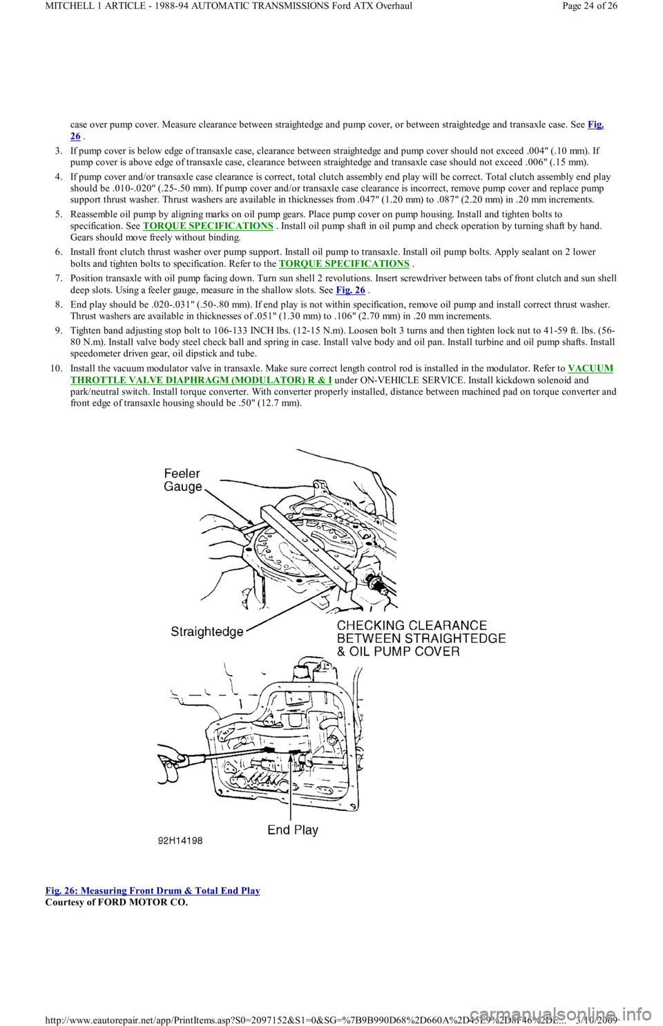
case over pump cover. Measure clearance between straightedge and pump cover, or between straightedge and transaxle case. See Fig.
26 .
3. If pump cover is below edge of transaxle case, clearance between straightedge and pump cover should not exceed .004" (.10 mm). If
pump cover is above edge of transaxle case, clearance between straightedge and transaxle case should not exceed .006" (.15 mm).
4. If pump cover and/or transaxle case clearance is correct, total clutch assembly end play will be correct. Total clutch assembly end play
should be .010-.020" (.25-.50 mm). If pump cover and/or transaxle case clearance is incorrect, remove pump cover and replace pump
support thrust washer. Thrust washers are available in thicknesses from .047" (1.20 mm) to .087" (2.20 mm) in .20 mm increments.
5. Reassemble oil pump by aligning marks on oil pump gears. Place pump cover on pump housing. Install and tighten bolts to
specification. See TORQUE SPECIFICATIONS
. Install oil pump shaft in oil pump and check operation by turning shaft by hand.
Gears should move freely without binding.
6. Install front clutch thrust washer over pump support. Install oil pump to transaxle. Install oil pump bolts. Apply sealant on 2 lower
bolts and tighten bolts to specification. Refer to the TORQUE SPECIFICATIONS
.
7. Position transaxle with oil pump facing down. Turn sun shell 2 revolutions. Insert screwdriver between tabs of front clutch and sun shell
deep slots. Using a feeler gauge, measure in the shallow slots. See Fig. 26
.
8. End play should be .020-.031" (.50-.80 mm). If end play is not within specification, remove oil pump and install correct thrust washer.
Thrust washers are available in thicknesses of .051" (1.30 mm) to .106" (2.70 mm) in .20 mm increments.
9. Tighten band adjusting stop bolt to 106-133 INCH lbs. (12-15 N.m). Loosen bolt 3 turns and then tighten lock nut to 41-59 ft. lbs. (56-
80 N.m). Install valve body steel check ball and spring in case. Install valve body and oil pan. Install turbine and oil pump sh aft s. In st al l
speedometer driven gear, oil dipstick and tube.
10. Install the vacuum modulator valve in transaxle. Make sure correct length control rod is installed in the modulator. Refer to VACUUM
THROTTLE VALVE DIAPHRAGM (MODULATOR) R & I under ON-VEHICLE SERVICE. Install kickdown solenoid and
park/neutral switch. Install torque converter. With converter properly installed, distance between machined pad on torque converter and
front edge of transaxle housing should be .50" (12.7 mm).
Fig. 26: Measuring Front Drum & Total End Play
Courtesy of FORD MOTOR CO.
Page 24 of 26 MITCHELL 1 ARTICLE - 1988-94 AUTOMATIC TRANSMISSIONS Ford ATX Overhaul
3/10/2009 http://www.eautorepair.net/app/PrintItems.asp?S0=2097152&S1=0&SG=%7B9B990D68%2D660A%2D45E9%2D8F46%2DE
...
Page 433 of 454
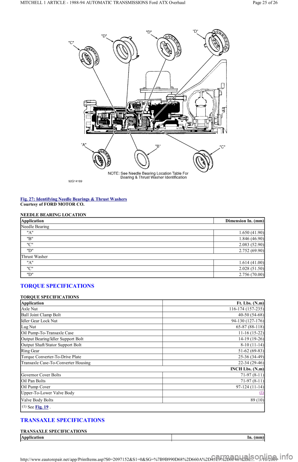
Fig. 27: Identifying Needle Bearings & Thrust Washers
Courtesy of FORD MOTOR CO.
NEEDLE BEARING LOCATION
TORQUE SPECIFICATIONS
TORQUE SPECIFICATIONS
TRANSAXLE SPECIFICATIONS
TRANSAXLE SPECIFICATIONS
ApplicationDimension In. (mm)
Needle Bearing
"A"1.650 (41.90)
"B"1.846 (46.90)
"C"2.083 (52.90)
"D"2.752 (69.90)
Thrust Washer
"A"1.614 (41.00)
"C"2.028 (51.50)
"D"2.756 (70.00)
ApplicationFt. Lbs. (N.m)
Axle Nut116-174 (157-235)
Ball Joint Clamp Bolt40-50 (54-68)
Idler Gear Lock Nut94-130 (127-176)
Lug Nut65-87 (88-118)
Oil Pump-To-Transaxle Case11-16 (15-22)
Output Bearing/Idler Support Bolt14-19 (19-26)
Output Shaft/Stator Support Bolt8-10 (11-14)
Ring Gear51-62 (69-83)
Torque Converter-To-Drive Plate25-36 (34-49)
Transaxle Case-To-Converter Housing22-34 (29-46)
INCH Lbs. (N.m)
Go ve r n o r C o ve r B o l t s71-97 (8-11)
Oil Pan Bolts71-97 (8-11)
Oil Pump Cover97-124 (11-14)
Upper-To-Lower Valve Body(1)
Valve Body Bolts89 (10)
(1)See Fig. 19 .
ApplicationIn. (mm)
Page 25 of 26 MITCHELL 1 ARTICLE - 1988-94 AUTOMATIC TRANSMISSIONS Ford ATX Overhaul
3/10/2009 http://www.eautorepair.net/app/PrintItems.asp?S0=2097152&S1=0&SG=%7B9B990D68%2D660A%2D45E9%2D8F46%2DE
...
Page 434 of 454
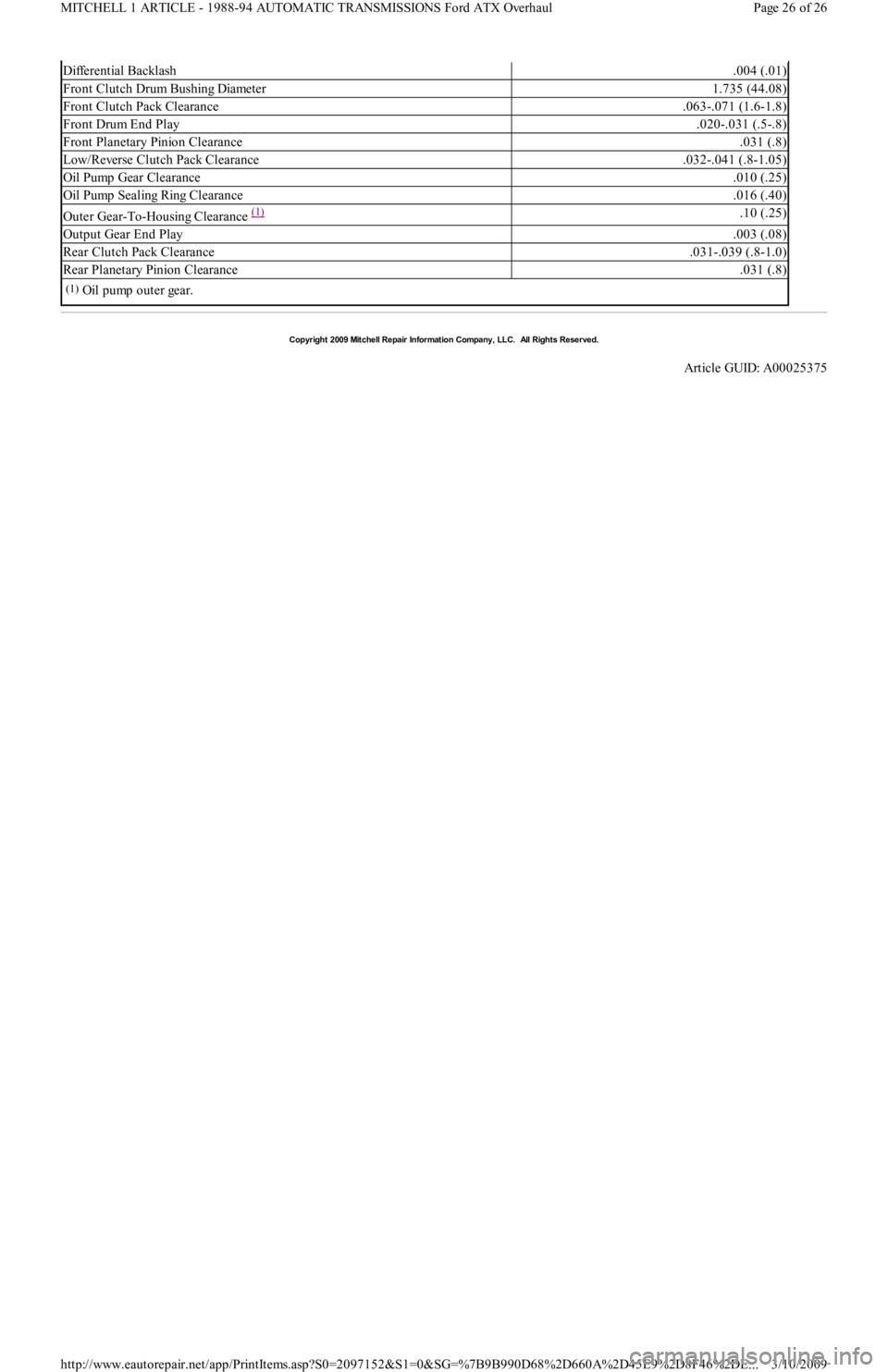
Differential Backlash.004 (.01)
Front Clutch Drum Bushing Diameter1.735 (44.08)
Front Clutch Pack Clearance.063-.071 (1.6-1.8)
Front Drum End Play.020-.031 (.5-.8)
Front Planetary Pinion Clearance.031 (.8)
Low/Reverse Clutch Pack Clearance.032-.041 (.8-1.05)
Oil Pump Gear Clearance.010 (.25)
Oil Pump Sealing Ring Clearance.016 (.40)
Outer Gear-To-Housing Clearance (1) .10 (.25)
Output Gear End Play.003 (.08)
Rear Clutch Pack Clearance.031-.039 (.8-1.0)
Rear Planetary Pinion Clearance.031 (.8)
(1)Oil pump outer gear.
Copyr ight 2009 Mitchell Repair Information Company, LLC. All Rights Reserved.
Article GUID: A00025375
Page 26 of 26 MITCHELL 1 ARTICLE - 1988-94 AUTOMATIC TRANSMISSIONS Ford ATX Overhaul
3/10/2009 http://www.eautorepair.net/app/PrintItems.asp?S0=2097152&S1=0&SG=%7B9B990D68%2D660A%2D45E9%2D8F46%2DE
...
Page 435 of 454
Back To Article
T RANSMISSION REMOVAL & INST ALLAT ION - A/T
1988-93 T RANSMISSION SERVICING Ford Motor Co. T ransm ission Rem oval & Installation
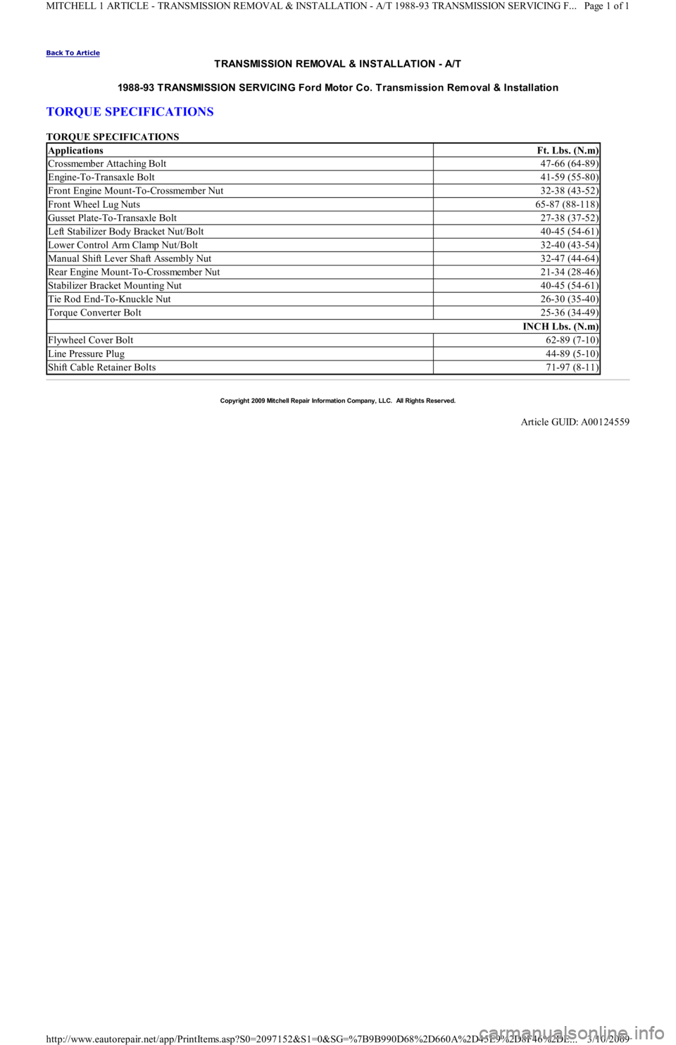
TORQUE SPECIFICATIONS
TORQUE SPECIFICATIONS
ApplicationsFt. Lbs. (N.m)
Crossmember Attaching Bolt47-66 (64-89)
Engine-To-Transaxle Bolt41-59 (55-80)
Front Engine Mount-To-Crossmember Nut32-38 (43-52)
Front Wheel Lug Nuts65-87 (88-118)
Gusset Plate-To-Transaxle Bolt27-38 (37-52)
Left Stabilizer Body Bracket Nut/Bolt40-45 (54-61)
Lower Control Arm Clamp Nut/Bolt32-40 (43-54)
Manual Shift Lever Shaft Assembly Nut32-47 (44-64)
Rear Engine Mount-To-Crossmember Nut21-34 (28-46)
Stabilizer Bracket Mounting Nut40-45 (54-61)
Tie Rod End-To-Knuckle Nut26-30 (35-40)
Torque Converter Bolt25-36 (34-49)
INCH Lbs. (N.m)
Flywheel Cover Bolt62-89 (7-10)
Line Pressure Plug44-89 (5-10)
Shift Cable Retainer Bolts71-97 (8-11)
Copyr ight 2009 Mitchell Repair Information Company, LLC. All Rights Reserved.
Article GUID: A00124559
Page 1 of 1 MITCHELL 1 ARTICLE - TRANSMISSION REMOVAL & INSTALLATION - A/T 1988-93 TRANSMISSION SERVICING F
...
3/10/2009 http://www.eautorepair.net/app/PrintItems.asp?S0=2097152&S1=0&SG=%7B9B990D68%2D660A%2D45E9%2D8F46%2DE
...
Page 436 of 454
Back To Article
T RANSMISSION SERVICING - A/T
1988-93 T RANSMISSION SERVICING Ford Motor Co. Autom atic T ransm ission
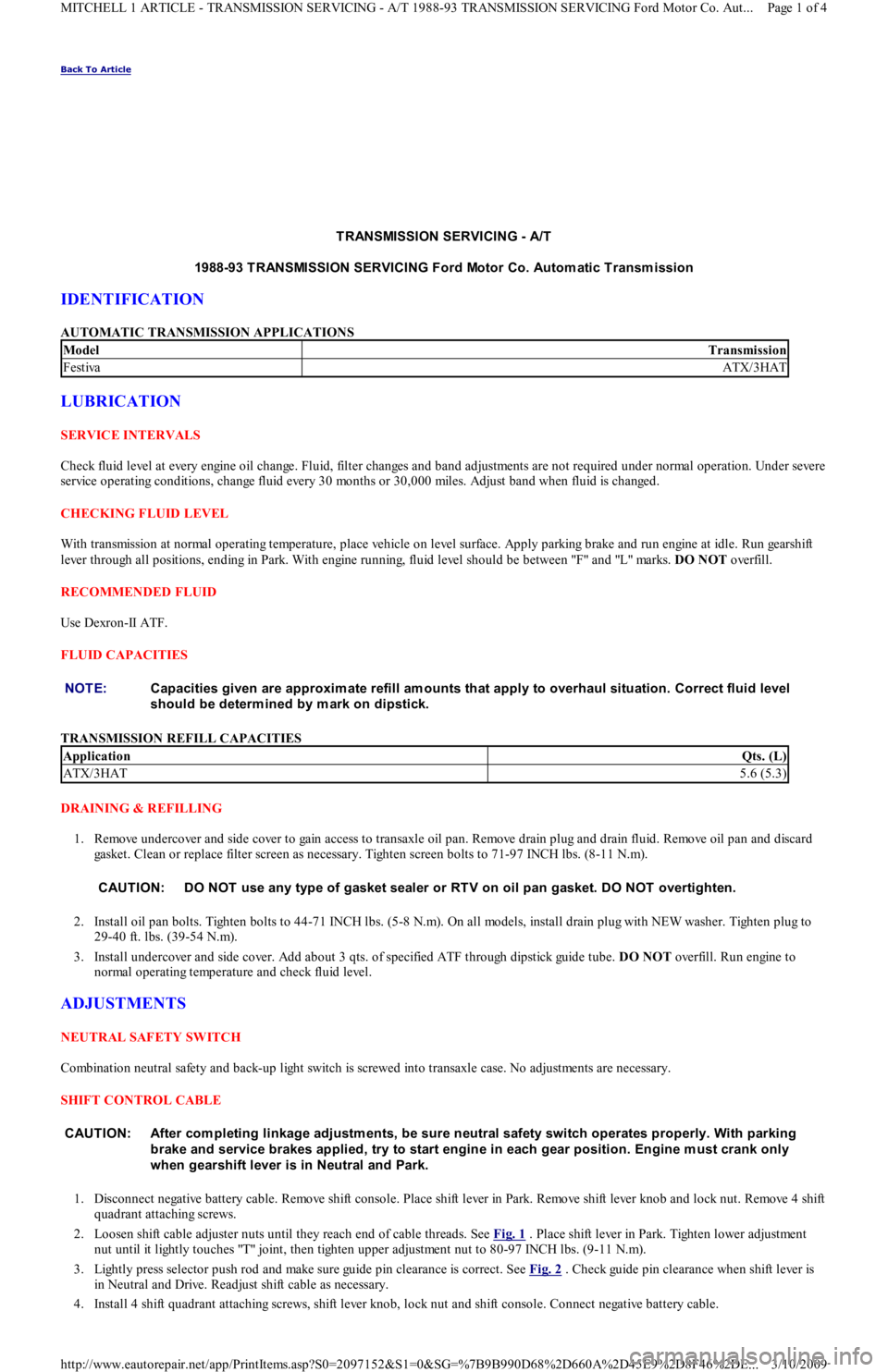
IDENTIFICATION
AUTOMATIC TRANSMISSION APPLICATIONS
LUBRICATION
SERVICE INTERVALS
Check fluid level at every engine oil change. Fluid, filter changes and band adjustments are not required under normal operation. Under severe
service operating conditions, change fluid every 30 months or 30,000 miles. Adjust band when fluid is changed.
CHECKING FLUID LEVEL
With transmission at normal operating temperature, place vehicle on level surface. Apply parking brake and run engine at idle. Run gearshift
lever through all positions, ending in Park. With engine running, fluid level should be between "F" and "L" marks. DO NOT overfill.
RECOMMENDED FLUID
Use Dexron-II ATF.
FLUID CAPACITIES
TRANSMISSION REFILL CAPACITIES
DRAINING & REFILLING
1. Remove undercover and side cover to gain access to transaxle oil pan. Remove drain plug and drain fluid. Remove oil pan and discard
gasket. Clean or replace filter screen as necessary. Tighten screen bolts to 71-97 INCH lbs. (8-11 N.m).
2. Install oil pan bolts. Tighten bolts to 44-71 INCH lbs. (5-8 N.m). On all models, install drain plug with NEW washer. Tighten plug to
29-40 ft. lbs. (39-54 N.m).
3. Install undercover and side cover. Add about 3 qts. of specified ATF through dipstick guide tube. DO NOT overfill. Run engine to
normal operating temperature and check fluid level.
ADJUSTMENTS
NEUTRAL SAFETY SWITCH
Combination neutral safety and back-up light switch is screwed into transaxle case. No adjustments are necessary.
SHIFT CONTROL CABLE
1. Disconnect negative battery cable. Remove shift console. Place shift lever in Park. Remove shift lever knob and lock nut. Remove 4 shift
quadrant attaching screws.
2. Loosen shift cable adjuster nuts until they reach end of cable threads. See Fig. 1
. Place shift lever in Park. Tighten lower adjustment
nut until it lightly touches "T" joint, then tighten upper adjustment nut to 80-97 INCH lbs. (9-11 N.m).
3. Lightly press selector push rod and make sure guide pin clearance is correct. See Fig. 2
. Check guide pin clearance when shift lever is
in Neutral and Drive. Readjust shift cable as necessary.
4. Install 4 shift quadrant attaching screws, shift lever knob, lock nut and shift console. Connect negative battery cable.
ModelTransmission
FestivaATX/3HAT
NOTE:Capacities given are approxim ate refill am ounts that apply to overhaul situation. Correct fluid level
should be determ ined by m ark on dipstick.
ApplicationQts. (L)
ATX/3HAT5.6 (5.3)
CAUT ION: DO NOT use any type of gasket sealer or RT V on oil pan gasket. DO NOT overtighten.
CAUT ION: After com pleting linkage adjustm ents, be sure neutral safety switch operates properly. With parking
brake and service brakes applied, try to start engine in each gear position. Engine m ust crank only
when gearshift lever is in Neutral and Park.
Page 1 of 4 MITCHELL 1 ARTICLE - TRANSMISSION SERVICING - A/T 1988-93 TRANSMISSION SERVICING Ford Motor Co. Aut
...
3/10/2009 http://www.eautorepair.net/app/PrintItems.asp?S0=2097152&S1=0&SG=%7B9B990D68%2D660A%2D45E9%2D8F46%2DE
...
Page 437 of 454
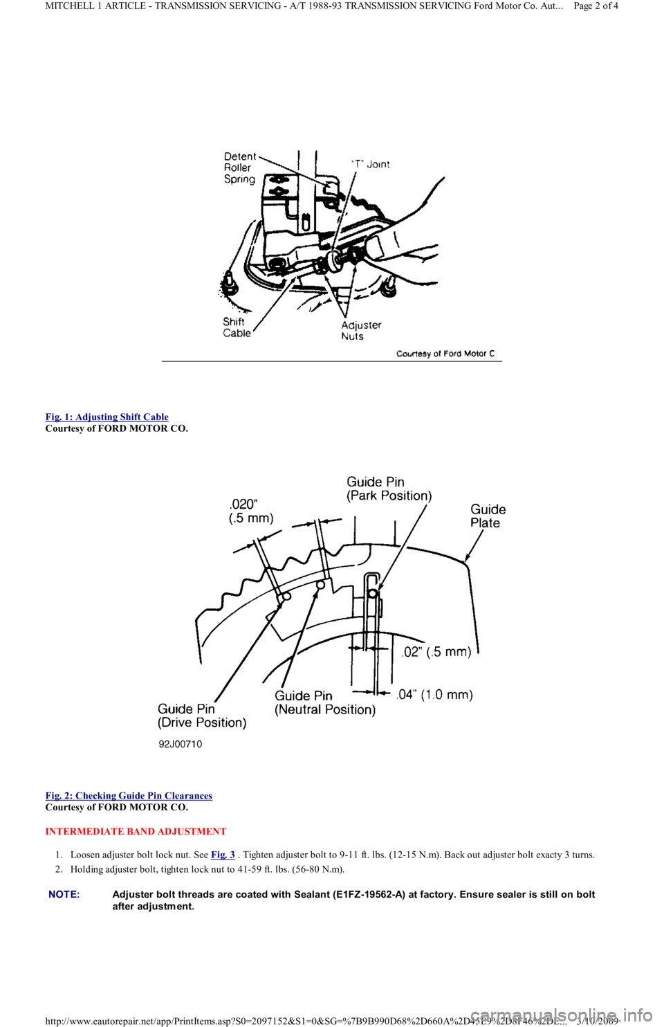
Fig. 1: Adjusting Shift Cable
Courtesy of FORD MOTOR CO.
Fig. 2: Checking Guide Pin Clearances
Courtesy of FORD MOTOR CO.
INTERMEDIATE BAND ADJUSTMENT
1. Loosen adjuster bolt lock nut. See Fig. 3
. Tighten adjuster bolt to 9-11 ft. lbs. (12-15 N.m). Back out adjuster bolt exacty 3 turns.
2. Holding adjuster bolt, tighten lock nut to 41-59 ft. lbs. (56-80 N.m).
NOTE:Adjuster bolt threads are coated with Sealant (E1FZ-19562-A) at factory. Ensure sealer is still on bolt
after adjustm ent.
Page 2 of 4 MITCHELL 1 ARTICLE - TRANSMISSION SERVICING - A/T 1988-93 TRANSMISSION SERVICING Ford Motor Co. Aut
...
3/10/2009 http://www.eautorepair.net/app/PrintItems.asp?S0=2097152&S1=0&SG=%7B9B990D68%2D660A%2D45E9%2D8F46%2DE
...
Page 438 of 454
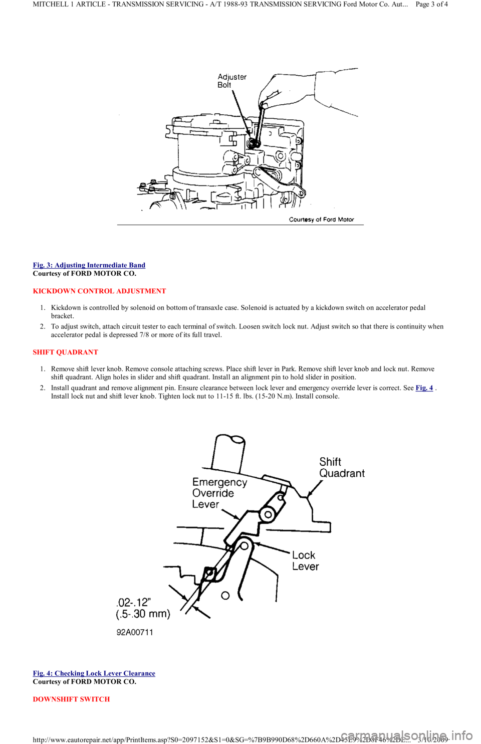
Fig. 3: Adjusting Intermediate Band
Courtesy of FORD MOTOR CO.
KICKDOWN CONTROL ADJUSTMENT
1. Kickdown is controlled by solenoid on bottom of transaxle case. Solenoid is actuated by a kickdown switch on accelerator pedal
bracket.
2. To adjust switch, attach circuit tester to each terminal of switch. Loosen switch lock nut. Adjust switch so that there is continuity when
accelerator pedal is depressed 7/8 or more of its full travel.
SHIFT QUADRANT
1. Remove shift lever knob. Remove console attaching screws. Place shift lever in Park. Remove shift lever knob and lock nut. Remo ve
shift quadrant. Align holes in slider and shift quadrant. Install an alignment pin to hold slider in position.
2. Install quadrant and remove alignment pin. Ensure clearance between lock lever and emergency override lever is correct. See Fig. 4
.
Install lock nut and shift lever knob. Tighten lock nut to 11-15 ft. lbs. (15-20 N.m). Install console.
Fig. 4: Checking Lock Lever Clearance
Courtesy of FORD MOTOR CO.
DOWNSHIFT SWITCH
Page 3 of 4 MITCHELL 1 ARTICLE - TRANSMISSION SERVICING - A/T 1988-93 TRANSMISSION SERVICING Ford Motor Co. Aut
...
3/10/2009 http://www.eautorepair.net/app/PrintItems.asp?S0=2097152&S1=0&SG=%7B9B990D68%2D660A%2D45E9%2D8F46%2DE
...
Page 439 of 454
1. Inspect wiring and components for shorts, corrosion, overheating, loose connections, or any other damage. Check 10-amp METER fu se.
Disconnect downshift solenoid.
2. With key off, voltage measured at Black/Blue wire should be zero volts. With key on and accelerator pedal fully depressed, voltage
should be greater than 10 volts. If Black/Blue wire is okay, remove downshift solenoid.
3. Apply battery voltage to downshift solenoid connector and ground case. Control rod should move freely when solenoid case is
grounded. If control rod does not move freely, replace downshift solenoid.
VACUUM DIAPHRAGM ROD
If transaxle shift points are incorrect, check for a defective vacuum diaphragm and replace if necessary. If diaphragm is operating correctly,
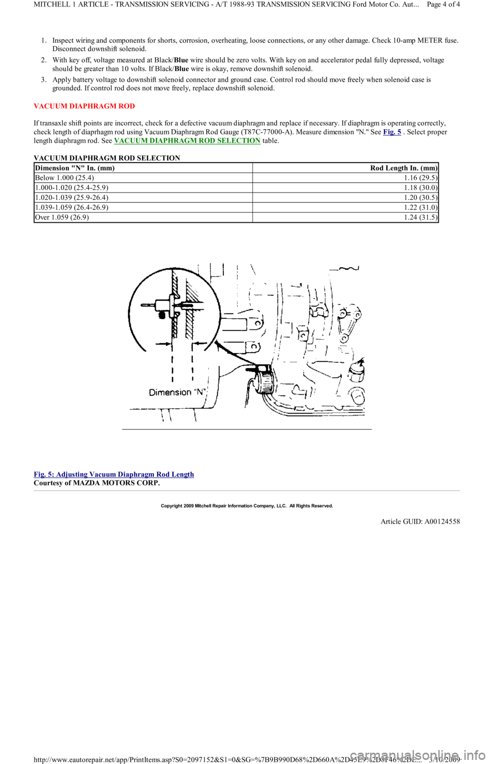
check length of diaprhagm rod using Vacuum Diaphragm Rod Gauge (T87C-77000-A). Measure dimension "N." See Fig. 5
. Select proper
length diaphragm rod. See VACUUM DIAPHRAGM ROD SELECTION
table.
VACUUM DIAPHRAGM ROD SELECTION
Fig. 5: Adjusting Vacuum Diaphragm Rod Length
Courtesy of MAZDA MOTORS CORP.
Dimension "N" In. (mm)Rod Length In. (mm)
Below 1.000 (25.4)1.16 (29.5)
1.000-1.020 (25.4-25.9)1.18 (30.0)
1.020-1.039 (25.9-26.4)1.20 (30.5)
1.039-1.059 (26.4-26.9)1.22 (31.0)
Over 1.059 (26.9)1.24 (31.5)
Copyr ight 2009 Mitchell Repair Information Company, LLC. All Rights Reserved.
Article GUID: A00124558
Page 4 of 4 MITCHELL 1 ARTICLE - TRANSMISSION SERVICING - A/T 1988-93 TRANSMISSION SERVICING Ford Motor Co. Aut
...
3/10/2009 http://www.eautorepair.net/app/PrintItems.asp?S0=2097152&S1=0&SG=%7B9B990D68%2D660A%2D45E9%2D8F46%2DE
...
Page 440 of 454
Back To Article
CLUTCH
1988-93 Clutch
DESCRIPTION
The clutch is single-disc type, using a diaphragm spring to engage pressure plate. Clutch operation is controlled by a mechanical release
system consisting of clutch pedal, cable, release lever and release bearing.
ADJUSTMENTS
CLUTCH PEDAL FREE PLAY
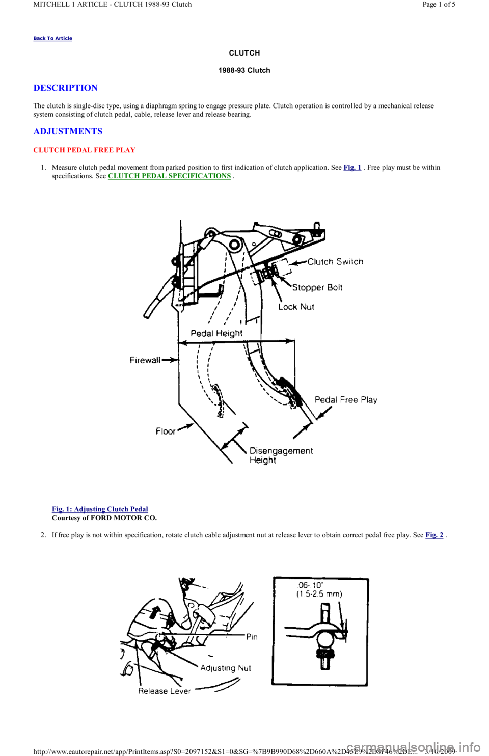
1. Measure clutch pedal movement from parked position to first indication of clutch application. See Fig. 1
. Free play must be within
specifications. See CLUTCH PEDAL SPECIFICATIONS
.
Fig. 1: Adjusting Clutch Pedal
Courtesy of FORD MOTOR CO.
2. If free play is not within specification, rotate clutch cable adjustment nut at release lever to obtain correct pedal free play. See Fig. 2
.
Page 1 of 5 MITCHELL 1 ARTICLE - CLUTCH 1988-93 Clutch
3/10/2009 http://www.eautorepair.net/app/PrintItems.asp?S0=2097152&S1=0&SG=%7B9B990D68%2D660A%2D45E9%2D8F46%2DE
...