FORD FESTIVA 1991 Service Manual
Manufacturer: FORD, Model Year: 1991, Model line: FESTIVA, Model: FORD FESTIVA 1991Pages: 454, PDF Size: 9.53 MB
Page 411 of 454
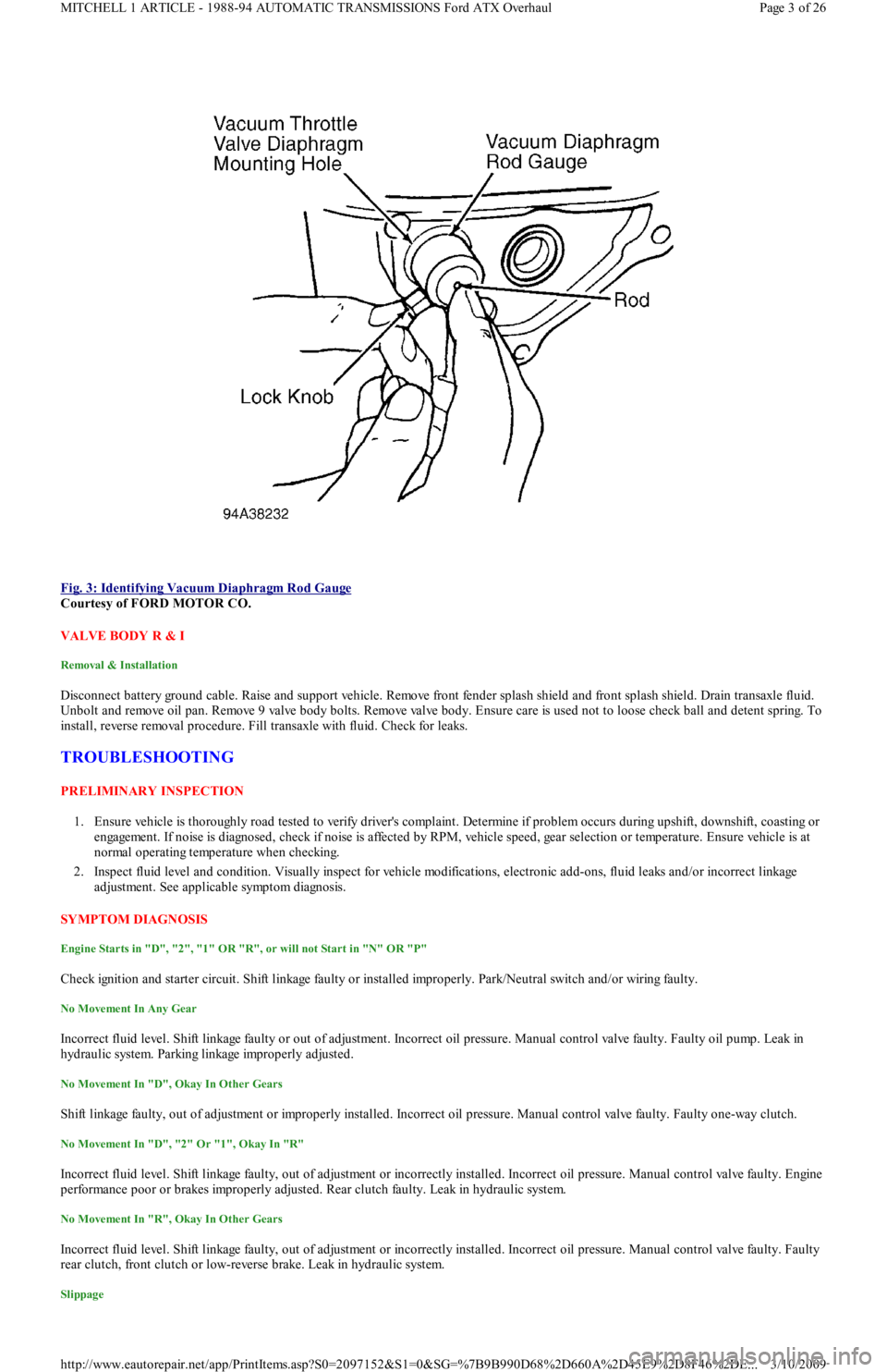
Fig. 3: Identifying Vacuum Diaphragm Rod Gauge
Courtesy of FORD MOTOR CO.
VALVE BODY R & I
Removal & Installation
Disconnect battery ground cable. Raise and support vehicle. Remove front fender splash shield and front splash shield. Drain transaxle fluid.
Unbolt and remove oil pan. Remove 9 valve body bolts. Remove valve body. Ensure care is used not to loose check ball and detent spring. To
install, reverse removal procedure. Fill transaxle with fluid. Check for leaks.
TROUBLESHOOTING
PRELIMINARY INSPECTION
1. Ensure vehicle is thoroughly road tested to verify driver's complaint. Determine if problem occurs during upshift, downshift, coasting or
engagement. If noise is diagnosed, check if noise is affected by RPM, vehicle speed, gear selection or temperature. Ensure vehicle is at
normal operating temperature when checking.
2. Inspect fluid level and condition. Visually inspect for vehicle modifications, electronic add-ons, fluid leaks and/or incorrect linkage
adjustment. See applicable symptom diagnosis.
SYMPTOM DIAGNOSIS
Engine Starts in "D", "2", "1" OR "R", or will not Start in "N" OR "P"
Check ignition and starter circuit. Shift linkage faulty or installed improperly. Park/Neutral switch and/or wiring faulty.
No Movement In Any Gear
Incorrect fluid level. Shift linkage faulty or out of adjustment. Incorrect oil pressure. Manual control valve faulty. Faulty oil pump. Leak in
hydraulic system. Parking linkage improperly adjusted.
No Movement In "D", Okay In Other Gears
Shift linkage faulty, out of adjustment or improperly installed. Incorrect oil pressure. Manual control valve faulty. Faulty one-way clutch.
No Movement In "D", "2" Or "1", Okay In "R"
Incorrect fluid level. Shift linkage faulty, out of adjustment or incorrectly installed. Incorrect oil pressure. Manual control valve faulty. Engine
performance poor or brakes improperly adjusted. Rear clutch faulty. Leak in hydraulic system.
No Movement In "R", Okay In Other Gears
Incorrect fluid level. Shift linkage faulty, out of adjustment or incorrectly installed. Incorrect oil pressure. Manual control valve faulty. Faulty
rear clutch, front clutch or low-reverse brake. Leak in hydraulic system.
Slippage
Page 3 of 26 MITCHELL 1 ARTICLE - 1988-94 AUTOMATIC TRANSMISSIONS Ford ATX Overhaul
3/10/2009 http://www.eautorepair.net/app/PrintItems.asp?S0=2097152&S1=0&SG=%7B9B990D68%2D660A%2D45E9%2D8F46%2DE
...
Page 412 of 454
ATF level incorrect or contaminated. Manual valve out of adjustment. Vacuum modulator faulty or leak in vacuum circuit. Fluid pressures
incorrect. Oil pump faulty. Leak in hydraulic circuit.
Vehicle Creeps In "N" Position
Shift linkage faulty, out of adjustment or incorrectly installed. Manual control valve faulty. Contaminated fluid. Faulty rear clutch.
Vehicle Creeps Excessively
Engine idle speed too high.
Vehicle Will Not Creep
Fluid level incorrect or fluid contaminated. Shift linkage faulty, out of adjustment or incorrectly installed. Engine idle too low. Manual
control valve faulty. Faulty oil pump. Leak in hydraulic system. Faulty front or rear clutch.
Low Maximum Speed & Poor Acceleration
Incorrect ATF level or contaminated fluid. Selector linkage out of adjustment. Engine stall speed incorrect. Poor engine performance. Brake
band faulty or out of adjustment. Faulty low-reverse brake, front clutch, rear clutch or hydraulic circuit.
Harsh "N" To "D" Engagement
Engine idle too high. Leak in vacuum circuit. Incorrect oil pressure. Manual control valve faulty. Faulty rear clutch. Low fluid level.
Harsh 1-2 Shift
Leak in vacuum circuit. Engine stall speed incorrect. Contaminated fluid. Manual control valve faulty. Band servo faulty. Brake band damaged
or out of adjustment.
Harsh 2-3 Shift
Leak in vacuum circuit. Incorrect oil pressure. Manual control valve faulty. Band servo or front clutch faulty. Brake band faulty.
Shift Shock Felt On Kickdown Downshift
Shift linkage damaged, out of adjustment or incorrectly installed. Leak in vacuum circuit. Kickdown solenoid, switch or wiring fau l t y.
Incorrect oil pressure. Manual control valve or governor valve faulty. Leak in hydraulic system.
2-1 Shift Shock With Lever In "1" Position
Leak in vacuum circuit. Engine stall speed incorrect. Manual control valve faulty. Contaminated fluid. Low-reverse brake faulty. Line pressure
high.
Shift Shock On Deceleration
Range selector out of adjustment. Vacuum diaphragm or piping faulty. Kickdown solenoid out of adjustment or faulty. Excessive line pressure.
M a n u a l va l ve fa u l t y. Go ve r n o r va l ve fa u l t y.
Vehicle Brakes In "R" Position
Band servo faulty. Contaminated fluid. Faulty rear clutch. Brake band damaged or out of adjustment. Parking linkage damaged or improperly
adjusted.
Vehicle Brakes On 1-2 Shift
Manual control valve faulty. Contaminated fluid. Front clutch or low-reverse brake faulty. One-way clutch faulty.
Vehicle Brakes On 2-3 Shift
Manual control valve faulty. Band servo faulty. Contaminated fluid. Brake band out of adjustment or damaged.
No Engine Braking In "1" Position
Shift linkage damaged, out of adjustment or installed incorrectly. Incorrect oil pressure. Manual control valve faulty. Contaminated fluid.
Low-reverse brake faulty. Leak in hydraulic system.
No Shift Shock; Slippage On 1-2 Shift
Incorrect fluid level. Shift linkage damaged, out of adjustment or incorrectly installed. Leak in vacuum circuit. Oil pressure incorrect. Manual
control valve faulty. Band servo faulty. Contaminated fluid. Brake band faulty. Leakage in hydraulic system.
No Shift Shock; Slippage When Manually Shifted From "1" To "2" Position
Incorrect fluid level. Shift linkage damaged, out of adjustment or installed incorrectly. Leak in vacuum circuit. Engine idle speed incorrect.
Engine stall speed incorrect. Manual control valve faulty. Contaminated fluid. Brake band out of adjustment or damaged. Oil pump faulty.
No Shift Shock; Slippage On 2-3 Shift
ATF contaminated or level incorrect. Shift linkage faulty. Vacuum modulator faulty or leak in vacuum circuit. Line pressure not correct. Band
servo faulty. Front clutch faulty. Leak in hydraulic system.
Slippage On 3-2 Kickdown
Page 4 of 26 MITCHELL 1 ARTICLE - 1988-94 AUTOMATIC TRANSMISSIONS Ford ATX Overhaul
3/10/2009 http://www.eautorepair.net/app/PrintItems.asp?S0=2097152&S1=0&SG=%7B9B990D68%2D660A%2D45E9%2D8F46%2DE
...
Page 413 of 454
Leak in vacuum circuit. Oil pressure incorrect. Manual valve faulty. Band servo faulty. Contaminated fluid. Front clutch faulty. Brake band
out of adjustment or damaged. Leak in hydraulic system.
Transaxle Slips In 1st Gear
Incorrect fluid level. Shift linkage faulty, out of adjustment or incorrectly installed. Incorrect oil pressure. Manual control valve faulty.
Contaminated fluid. Incorrect idle speed. Faulty kickdown solenoid, switch or wiring.
No 1-2 Shift
Shift linkage defective, out of adjustment or incorrectly installed. Leak in vacuum circuit. Faulty kickdown solenoid, switch or wiring.
Contaminated fluid. Manual control valve faulty. Governor valve faulty. Band servo faulty. Brake band out of adjustment. Leak in hydraulic
system. Rear clutch faulty.
No 2-3 Shift
Shift linkage defective, out of adjustment or incorrectly installed. Leak in vacuum circuit. Faulty kickdown solenoid, switch or wiring.
Contaminated fluid. Manual control valve, governor valve or band servo faulty. Leak in hydraulic system. Front clutch faulty.
No Lock-Up
Faulty torque converter, wiring or solenoid.
1-3 Shift; Skips 2nd
Contaminated fluid. Brake band out of adjustment or damaged. Leak in hydraulic system.
No 3-2 Downshift
Leak in vacuum circuit. Manual control valve, governor valve or band servo faulty. Contaminated fluid. Faulty front clutch. Brake band out of
adjustment of damaged. Leak in hydraulic system.
No 2-1 or 3-1 Downshift
Leak in vacuum circuit. Manual control valve, governor valve or band servo faulty. Contaminated fluid. Brake band out of adjustmen t o r
damaged. One-way clutch faulty.
Slippage When Accelerating In 3rd Gear Above Kickdown Speed
Shift linkage damaged, out of adjustment or installed incorrectly. Leak in vacuum circuit. Oil pressure incorrect. Manual control valve or
governor valve faulty. Contaminated fluid. Front clutch faulty. Leak in hydraulic system.
No Kickdown At Normal Speeds In 3rd Gear
Leak in vacuum circuit. Kickdown solenoid, switch or wiring faulty. Manual control valve or governor valve faulty. Contaminated fluid. Brake
band out of adjustment or damaged. Leak in hydraulic system.
1-2 & 2-3 Shift Points Too High
ATF contaminated or level incorrect. Vacuum modulator faulty or leak in vacuum circuit. Line pressures incorrect. Manual valve out of
adjustment. Governor valve faulty. Hydraulic circuit leaking.
3-2 & 2-1 Shift Points Too High
Shift linkage damaged, out of adjustment or incorrectly installed. Kickdown solenoid, switch or wiring faulty. Leak in vacuum circuit.
Incorrect oil pressure. Manual control valve or governor valve faulty. Leak in hydraulic system.
1-2 Or 2-3 Shifts With Shift Lever In "1" Position
Shift linkage damaged, out of adjustment or installed incorrectly. Manual control valve faulty. Leak in hydraulic system.
2-1 or 2-3 Shifts With Shift Lever In "2" Position
Shift linkage damaged, out of adjustment or installed incorrectly. Incorrect oil pressure. Manual control valve faulty.
Vehicle Moves In "P" Or Parking Gear Remains Engaged When
Shifted Out Of "P" Position
Shift linkage damaged, out of adjustment or incorrectly installed. Parking linkage out of adjustment or damaged.
Transaxle Noisy In "P" Or "N" Position
Incorrect fluid level. Incorrect oil pressure. Faulty rear clutch, oil pump, one-way clutch or planetary gear.
Transaxle Noisy In "D", "1", "2" or "R"
Oil pressure incorrect. Rear clutch, oil pump, one-way clutch or planetary gears faulty.
Transmission Overheats
ATF level incorrect. Engine stall speed and/or line pressure incorrect. Faulty band servo, front clutch, rear clutch, brake band, low-reverse
brake, oil pump, torque converter or planetary gear. Leak in hydraulic circuit.
Page 5 of 26 MITCHELL 1 ARTICLE - 1988-94 AUTOMATIC TRANSMISSIONS Ford ATX Overhaul
3/10/2009 http://www.eautorepair.net/app/PrintItems.asp?S0=2097152&S1=0&SG=%7B9B990D68%2D660A%2D45E9%2D8F46%2DE
...
Page 414 of 454
Differential Noise
ATF contaminated or level incorrect. Bearings worn or has excessive preload. Teeth on gears worn or damaged or has excessive backlash.
TESTING
PARK/NEUTRAL SWITCH TEST
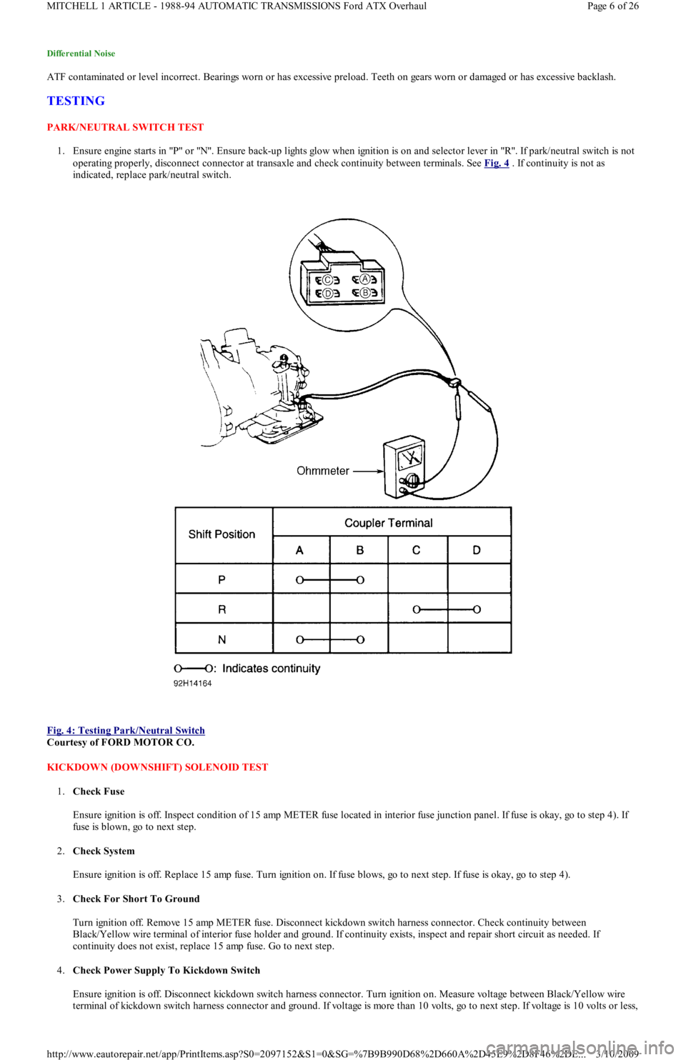
1. Ensure engine starts in "P" or "N". Ensure back-up lights glow when ignition is on and selector lever in "R". If park/neutral switch is not
operating properly, disconnect connector at transaxle and check continuity between terminals. See Fig. 4
. If continuity is not as
indicated, replace park/neutral switch.
Fig. 4: Testing Park/Neutral Switch
Courtesy of FORD MOTOR CO.
KICKDOWN (DOWNSHIFT) SOLENOID TEST
1.Check Fuse
Ensure ignition is off. Inspect condition of 15 amp METER fuse located in interior fuse junction panel. If fuse is okay, go to step 4). If
fuse is blown, go to next step.
2.Check System
Ensure ignition is off. Replace 15 amp fuse. Turn ignition on. If fuse blows, go to next step. If fuse is okay, go to step 4).
3.Check For Short To Ground
Turn ignition off. Remove 15 amp METER fuse. Disconnect kickdown switch harness connector. Check continuity between
Black/Yellow wire terminal of interior fuse holder and ground. If continuity exists, inspect and repair short circuit as needed. If
continuity does not exist, replace 15 amp fuse. Go to next step.
4.Check Power Supply To Kickdown Switch
Ensure ignition is off. Disconnect kickdown switch harness connector. Turn ignition on. Measure voltage between Black/Yellow wire
terminal of kickdown switch harness connector and ground. If voltage is more than 10 volts, go to next step. If voltage is 10 volts or less,
Page 6 of 26 MITCHELL 1 ARTICLE - 1988-94 AUTOMATIC TRANSMISSIONS Ford ATX Overhaul
3/10/2009 http://www.eautorepair.net/app/PrintItems.asp?S0=2097152&S1=0&SG=%7B9B990D68%2D660A%2D45E9%2D8F46%2DE
...
Page 415 of 454
inspect and repair circuit between switch harness connector and fuse panel.
5.Check Kickdown Switch
Turn ignition off. Check continuity between kickdown switch terminals. Continuity should only exist with accelerator fully depressed. I
f
switch is functioning correctly, go to next step. Replace switch if it failed testing. Road test vehicle to verify repair.
6.Check Circuit Between Kickdown Switch & Kickdown Solenoid
Ensure ignition is off. Disconnect kickdown switch harness connector. Disconnect kickdown solenoid harness connector. Check
continuity of White/Black wire between switch harness connector and solenoid harness connector. If continuity does not exist, inspect
and repair open circuit as needed. If continuity exists, check continuity between White/Black wire terminal at solenoid harness
connector and ground. If continuity exists, inspect and repair short circuit as needed. If continuity does not exist, replace kickdown
solenoid.
VACUUM THROTTLE VALVE DIAPHRAGM (MODULATOR) TEST
1.Check System Integrity
Inspect all vacuum hoses and connections for leaks or damage. Disconnect vacuum hose at diaphragm connection and inspect for
leaking ATF. Repair as needed. Go to next step.
2.Check Vacuum At Modulator
Ensure ignition is off. Disconnect vacuum hose at modulator valve and connect vacuum gauge to hose. Start and run engine at idle.
Vacuum should be 15-22 In. Hg. If vacuum is not within specification, inspect and repair vacuum hose. If vacuum is within specification,
go to next step.
3.Check Modulator Valve Function
Turn ignition off. Remove modulator valve from transaxle. Connect hand-held vacuum pump to valve. Apply 16-20 In. Hg of vacuum.
Ensure vacuum is held by valve. Release vacuum and verify that valve moves freely. If valve is functioning correctly, go to next step.
Replace valve if it fails testing.
4.Check Vacuum Diaphragm Rod
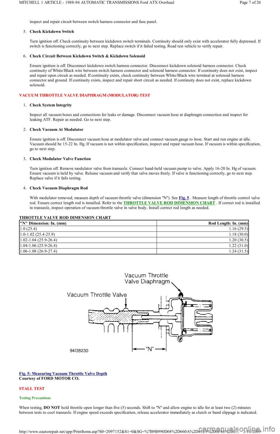
With modulator removed, measure depth of vacuum throttle valve (dimension "N"). See Fig. 5
. Measure length of throttle control valve
rod. Ensure correct length rod is installed. Refer to the THROTTLE VALVE ROD DIMENSION CHART
. If correct rod is installed
in transaxle, inspect operation of vacuum throttle valve in valve body. Install correct rod length as needed.
THROTTLE VALVE ROD DIMENSION CHART
Fig. 5: Measuring Vacuum Throttle Valve Depth
Courtesy of FORD MOTOR CO.
STALL TEST
Testing Precautions
When testing, DO NOT hold throttle open longer than five (5) seconds. Shift to "N" and allow engine to idle for at least two (2) minutes
between tests to cool transaxle. If engine speed exceeds specification, release accelerator immediately as clutch or band slippage is indicated.
"N" Dimension: In. (mm)Rod Length: In. (mm)
1.0 (25.4)1.16 (29.5)
1.0-1.02 (25.4-25.9)1.18 (30.0)
1.02-1.04 (25.9-26.4)1.20 (30.5)
1.04-1.06 (25.9-26.4)1.22 (31.0)
1.06-1.08 (26.9-27.4)1.24 (31.5)
Page 7 of 26 MITCHELL 1 ARTICLE - 1988-94 AUTOMATIC TRANSMISSIONS Ford ATX Overhaul
3/10/2009 http://www.eautorepair.net/app/PrintItems.asp?S0=2097152&S1=0&SG=%7B9B990D68%2D660A%2D45E9%2D8F46%2DE
...
Page 416 of 454
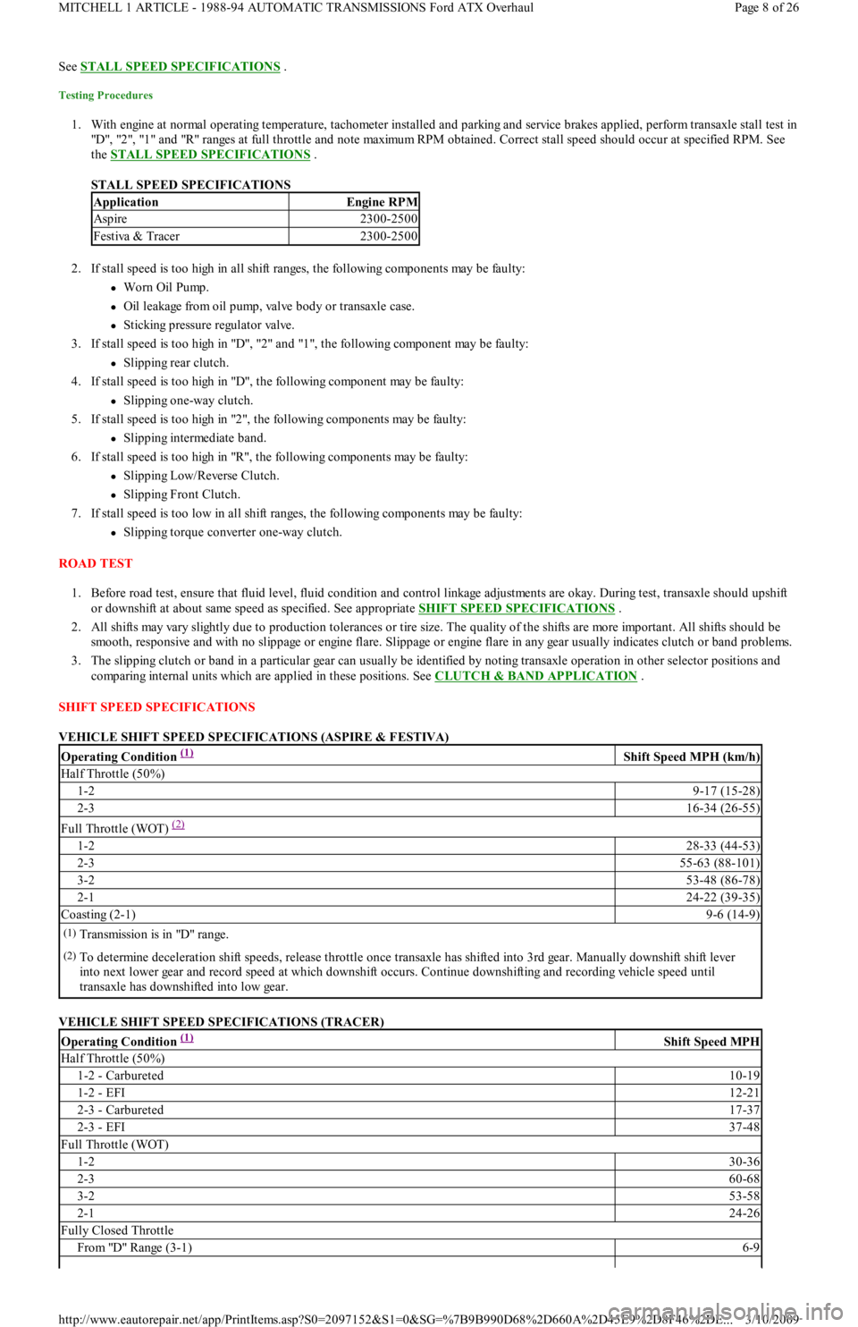
See STALL SPEED SPECIFICATIONS .
Testing Procedures
1. With engine at normal operating temperature, tachometer installed and parking and service brakes applied, perform transaxle stall test in
"D", "2", "1" and "R" ranges at full throttle and note maximum RPM obtained. Correct stall speed should occur at specified RPM. See
the STALL SPEED SPECIFICATIONS
.
STALL SPEED SPECIFICATIONS
2. If stall speed is too high in all shift ranges, the following components may be faulty:
Worn Oil Pump.
Oil leakage from oil pump, valve body or transaxle case.
Sticking pressure regulator valve.
3. If stall speed is too high in "D", "2" and "1", the following component may be faulty:
Slipping rear clutch.
4. If stall speed is too high in "D", the following component may be faulty:
Slipping one-way clutch.
5. If stall speed is too high in "2", the following components may be faulty:
Slipping intermediate band.
6. If stall speed is too high in "R", the following components may be faulty:
Slipping Low/Reverse Clutch.
Slipping Front Clutch.
7. If stall speed is too low in all shift ranges, the following components may be faulty:
Slipping torque converter one-way clutch.
ROAD TEST
1. Before road test, ensure that fluid level, fluid condition and control linkage adjustments are okay. During test, transaxle should upshift
or downshift at about same speed as specified. See appropriate SHIFT SPEED SPECIFICATIONS
.
2. All shifts may vary slightly due to production tolerances or tire size. The quality of the shifts are more important. All shifts should be
smooth, responsive and with no slippage or engine flare. Slippage or engine flare in any gear usually indicates clutch or band problems.
3. The slipping clutch or band in a particular gear can usually be identified by noting transaxle operation in other selector positions and
comparing internal units which are applied in these positions. See CLUTCH & BAND APPLICATION
.
SHIFT SPEED SPECIFICATIONS
VEHICLE SHIFT SPEED SPECIFICATIONS (ASPIRE & FESTIVA)
VEHICLE SHIFT SPEED SPECIFICATIONS (TRACER)
ApplicationEngine RPM
Aspire2300-2500
Festiva & Tracer2300-2500
Operating Condition (1) Shift Speed MPH (km/h)
Half Throttle (50%)
1-29-17 (15-28)
2-316-34 (26-55)
Full Throttle (WOT) (2)
1-228-33 (44-53)
2-355-63 (88-101)
3-253-48 (86-78)
2-124-22 (39-35)
Coasting (2-1)9-6 (14-9)
(1)Transmission is in "D" range.
(2)To determine deceleration shift speeds, release throttle once transaxle has shifted into 3rd gear. Manually downshift shift lever
into next lower gear and record speed at which downshift occurs. Continue downshifting and recording vehicle speed until
transaxle has downshifted into low gear.
Operating Condition (1) Shift Speed MPH
Half Throttle (50%)
1-2 - Carbureted10-19
1-2 - EFI12-21
2-3 - Carbureted17-37
2-3 - EFI37-48
Full Throttle (WOT)
1-230-36
2-360-68
3-253-58
2-124-26
Fully Closed Throttle
Fro m "D" Ran ge (3 -1 )6-9
Page 8 of 26 MITCHELL 1 ARTICLE - 1988-94 AUTOMATIC TRANSMISSIONS Ford ATX Overhaul
3/10/2009 http://www.eautorepair.net/app/PrintItems.asp?S0=2097152&S1=0&SG=%7B9B990D68%2D660A%2D45E9%2D8F46%2DE
...
Page 417 of 454
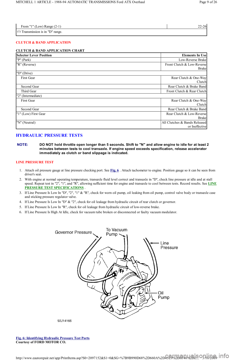
CLUTCH & BAND APPLICATION
CLUTCH & BAND APPLICATION CHART
HYDRAULIC PRESSURE TESTS
LINE PRESSURE TEST
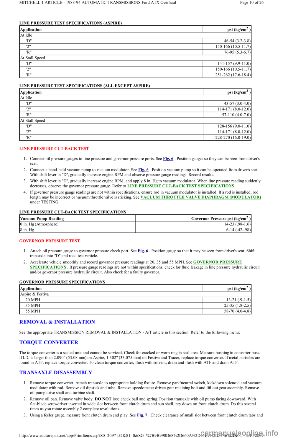
1. Attach oil pressure gauge at line pressure checking port. See Fig. 6
. Attach tachometer to engine. Position gauge so it can be seen from
driver's seat.
2. With engine at normal operating temperature, transaxle fluid level correct and transaxle in "D", check line pressure at idle and at stall
sp eed . Rep eat t est in "2 ", "1 ", an d "R", al l o win g su fficien t t ime for engine and transaxle to cool between tests. Record results. See LINE
PRESSURE TEST SPECIFICATIONS .
3 . If Lin e Pressu re Is Lo w In "D", "2 ", "1 " & "R", ch eck fo r worn oil pump, oil leaking from oil pump, control valve body or transaxle case
and sticking pressure regulator valve.
4. If Line Pressure Is Low In "D" & "2", check for oil leakage from hydraulic circuit of rear clutch or governor.
5. If Line Pressure Is Low In "R", check for oil leakage from hydraulic circuit of low-reverse brake.
6. If Line Pressure Is High At Idle, check for vacuum tube broken or disconnected or faulty vacuum modulator.
Fig. 6: Identifying Hydraulic Pressure Test Ports
Courtesy of FORD MOTOR CO.
From "1" (Low) Range (2-1)22-26
(1)Transmission is in "D" range.
Selector Lever PositionElements In Use
"P" (Park)Low-Reverse Brake
"R" (Reverse)Front Clutch & Low-Reverse
Brake
"D" (Drive)
First GearRear Clutch & One-Way
Clutch
Second GearRear Clutch & Brake Band
Third GearFront Clutch & Rear Clutch
"2" (Intermediate)
First GearRear Clutch & One-Way
Clutch
Second GearRear Clutch & Brake Band
"1" (Low) First GearRear Clutch & Low-Reverse
Brake
"N" (Neutral)All Clutches & Bands Released
o r In effect ive
NOTE:DO NOT hold throttle open longer than 5 seconds. Shift to "N" and allow engine to idle for at least 2
m inutes between tests to cool transaxle. If engine speed exceeds specification, release accelerator
im m ediately as clutch or band slippage is indicated.
Page 9 of 26 MITCHELL 1 ARTICLE - 1988-94 AUTOMATIC TRANSMISSIONS Ford ATX Overhaul
3/10/2009 http://www.eautorepair.net/app/PrintItems.asp?S0=2097152&S1=0&SG=%7B9B990D68%2D660A%2D45E9%2D8F46%2DE
...
Page 418 of 454
LINE PRESSURE TEST SPECIFICATIONS (ASPIRE)
LINE PRESSURE TEST SPECIFICATIONS (ALL EXCEPT ASPIRE)
LINE PRESSURE CUT-BACK TEST
1. Connect oil pressure gauges to line pressure and governor pressure ports. See Fig. 6
. Position gauges so they can be seen from driver's
seat.
2. Connect a hand-held vacuum pump to vacuum modulator. See Fig. 6
. Position vacuum pump so it can be operated from driver's seat.
With shift lever in "D", gradually increase engine RPM and observe pressure gauge readings. Record results.
3. With shift lever in "D", gradually increase engine RPM, and apply 8 in. Hg to vacuum modulator. When line pressure reading suddenly
decreases, observe the governor pressure gauge. Refer to LINE PRESSURE CUT
-BACK TEST SPECIFICATIONS .
4. If governor pressure gauge readings are not within specifications, ensure rod in vacuum modulator is installed. If a rod is installed, rod
length may be incorrect or vacuum throttle valve is sticking. See VACUUM THROTTLE VALVE DIAPHRAGM (MODULATOR)
under TESTING.
LINE PRESSURE CUT-BACK TEST SPECIFICATIONS
GOVERNOR PRESSURE TEST
1. Attach oil pressure gauge to governor pressure check port. See Fig. 6
. Position gauge so that it may be seen from driver's seat. Shift
transaxle into "D" and road test vehicle.
2. Accelerate vehicle smoothly and record governor pressure readings at 20, 35 and 55 MPH. See GOVERNOR PRESSURE
SPECIFICATIONS . If pressure gauge readings are not within specifications, check for fluid leakage in line pressure hydraulic circuit
and/or governor pressure hydraulic circuit. Also check for a faulty governor.
GOVERNOR PRESSURE SPECIFICATIONS
REMOVAL & INSTALLATION
See the appropriate TRANSMISSION REMOVAL & INSTALLATION - A/T article in this section. Refer to the following menu:
TORQUE CONVERTER
The torque converter is a sealed unit and cannot be serviced. Check for cracked or worn ring in seal area. Measure bushing in converter boss.
If I.D. is larger than 2.090" (53.08 mm) on Aspire, 1.302" (33.075 mm) on Festiva and Tracer, replace torque converter. If metal particles are
found in ATF, replace torque converter. To clean torque converter, flush with solvent, drain and flush with ATF and drain ATF.
TRANSAXLE DISASSEMBLY
1. Remove torque converter. Attach transaxle to appropriate holding fixture. Remove park/neutral switch, kickdown solenoid and vacuum
modulator with rod. Remove oil dipstick and tube. Remove speedometer driven gear retaining bolt and lift out gear assembly. Remove
oil pump drive shaft and turbine shaft.
2. Remove oil pan. Remove valve body. DO NOT lose check ball and spring. Position transaxle with oil pump facing downward. With
flat-blade screwdriver inserted in wide slot between front clutch drum and sun shell, pry down on front clutch drum. Do this seve r a l
times as you rotate assembly 2 complete revolutions.
3. Using a feeler gauge, measure front clutch drum end play. See Fig. 7
. Check clearance of small slot between front clutch drum tabs and
Applicationpsi (kg/cm2 )
At Idle
"D"46-54 (3.2-3.8)
"2 "150-166 (10.5-11.7)
"R"76-95 (5.3-6.7)
At Stall Speed
"D"141-157 (9.9-11.0)
"2 "150-166 (10.5-11.7)
"R"251-262 (17.6-18.4)
Applicationpsi (kg/cm2 )
At Idle
"D"43-57 (3.0-4.0)
"2 "114-171 (8.0-12.0)
"R"57-110 (4.0-7.0)
At Stall Speed
"D"128-156 (9.0-11.0)
"2 "114-171 (8.0-12.0)
"R"228-270 (16.0-19.0)
Vacuum Pump ReadingGovernor Pressure psi (kg/cm2 )
0 in. Hg (Atmosphere)14-23 (.98-1.6)
8 in. Hg6-14 (.42-.98)
Applicationpsi (kg/cm2 )
Aspire & Festiva
20 MPH13-21 (.9-1.5)
35 MPH25-35 (1.8-2.5)
55 MPH58-70 (4.0-4.8)
Page 10 of 26 MITCHELL 1 ARTICLE - 1988-94 AUTOMATIC TRANSMISSIONS Ford ATX Overhaul
3/10/2009 http://www.eautorepair.net/app/PrintItems.asp?S0=2097152&S1=0&SG=%7B9B990D68%2D660A%2D45E9%2D8F46%2DE
...
Page 419 of 454
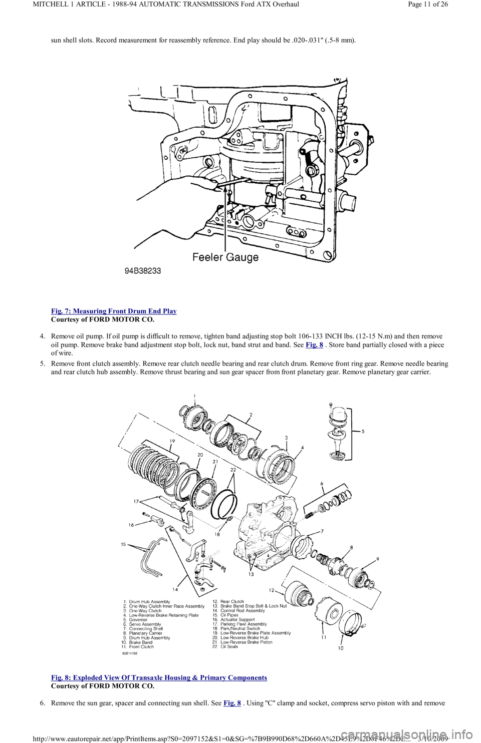
sun shell slots. Record measurement for reassembly reference. End play should be .020-.031" (.5-8 mm).
Fig. 7: Measuring Front Drum End Play
Courtesy of FORD MOTOR CO.
4. Remove oil pump. If oil pump is difficult to remove, tighten band adjusting stop bolt 106-133 INCH lbs. (12-15 N.m) and then remove
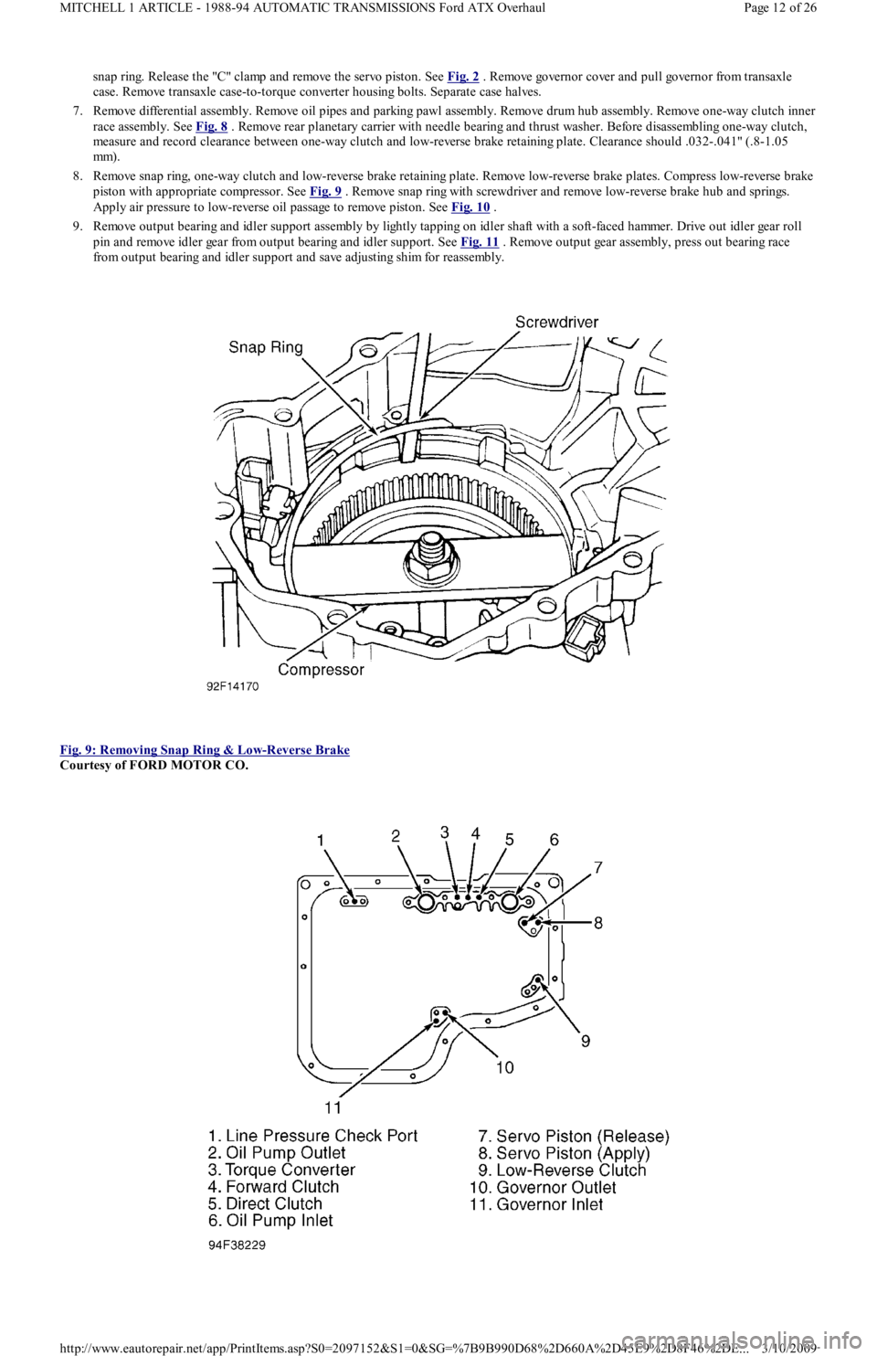
oil pump. Remove brake band adjustment stop bolt, lock nut, band strut and band. See Fig. 8
. Store band partially closed with a piece
of wire.
5. Remove front clutch assembly. Remove rear clutch needle bearing and rear clutch drum. Remove front ring gear. Remove needle bearing
and rear clutch hub assembly. Remove thrust bearing and sun gear spacer from front planetary gear. Remove planetary gear carrier.
Fig. 8: Exploded View Of Transaxle Housing & Primary Components
Courtesy of FORD MOTOR CO.
6. Remove the sun gear, spacer and connecting sun shell. See Fig. 8
. Using "C" clamp and socket, compress servo piston with and remove
Page 11 of 26 MITCHELL 1 ARTICLE - 1988-94 AUTOMATIC TRANSMISSIONS Ford ATX Overhaul
3/10/2009 http://www.eautorepair.net/app/PrintItems.asp?S0=2097152&S1=0&SG=%7B9B990D68%2D660A%2D45E9%2D8F46%2DE
...
Page 420 of 454
snap ring. Release the "C" clamp and remove the servo piston. See Fig. 2 . R e mo ve go ve r n o r c o ve r a n d p u l l go ve r n o r fr o m t r a n sa xl e
case. Remove transaxle case-to-torque converter housing bolts. Separate case halves.
7. Remove differential assembly. Remove oil pipes and parking pawl assembly. Remove drum hub assembly. Remove one-way clutch inner
race assembly. See Fig. 8
. Remove rear planetary carrier with needle bearing and thrust washer. Before disassembling one-way clutch,
measure and record clearance between one-way clutch and low-reverse brake retaining plate. Clearance should .032-.041" (.8-1.05
mm).
8. Remove snap ring, one-way clutch and low-reverse brake retaining plate. Remove low-reverse brake plates. Compress low-reverse brake
piston with appropriate compressor. See Fig. 9
. Remove snap ring with screwdriver and remove low-reverse brake hub and springs.
Apply air pressure to low-reverse oil passage to remove piston. See Fig. 10
.
9. Remove output bearing and idler support assembly by lightly tapping on idler shaft with a soft-faced hammer. Drive out idler gear roll
pin and remove idler gear from output bearing and idler support. See Fig. 11
. Remove output gear assembly, press out bearing race
from output bearing and idler support and save adjusting shim for reassembly.
Fig. 9: Removing Snap Ring & Low
-Reverse Brake
Courtesy of FORD MOTOR CO.
Page 12 of 26 MITCHELL 1 ARTICLE - 1988-94 AUTOMATIC TRANSMISSIONS Ford ATX Overhaul
3/10/2009 http://www.eautorepair.net/app/PrintItems.asp?S0=2097152&S1=0&SG=%7B9B990D68%2D660A%2D45E9%2D8F46%2DE
...