FORD FIESTA 1989 Service Repair Manual
Manufacturer: FORD, Model Year: 1989, Model line: FIESTA, Model: FORD FIESTA 1989Pages: 296, PDF Size: 10.65 MB
Page 111 of 296
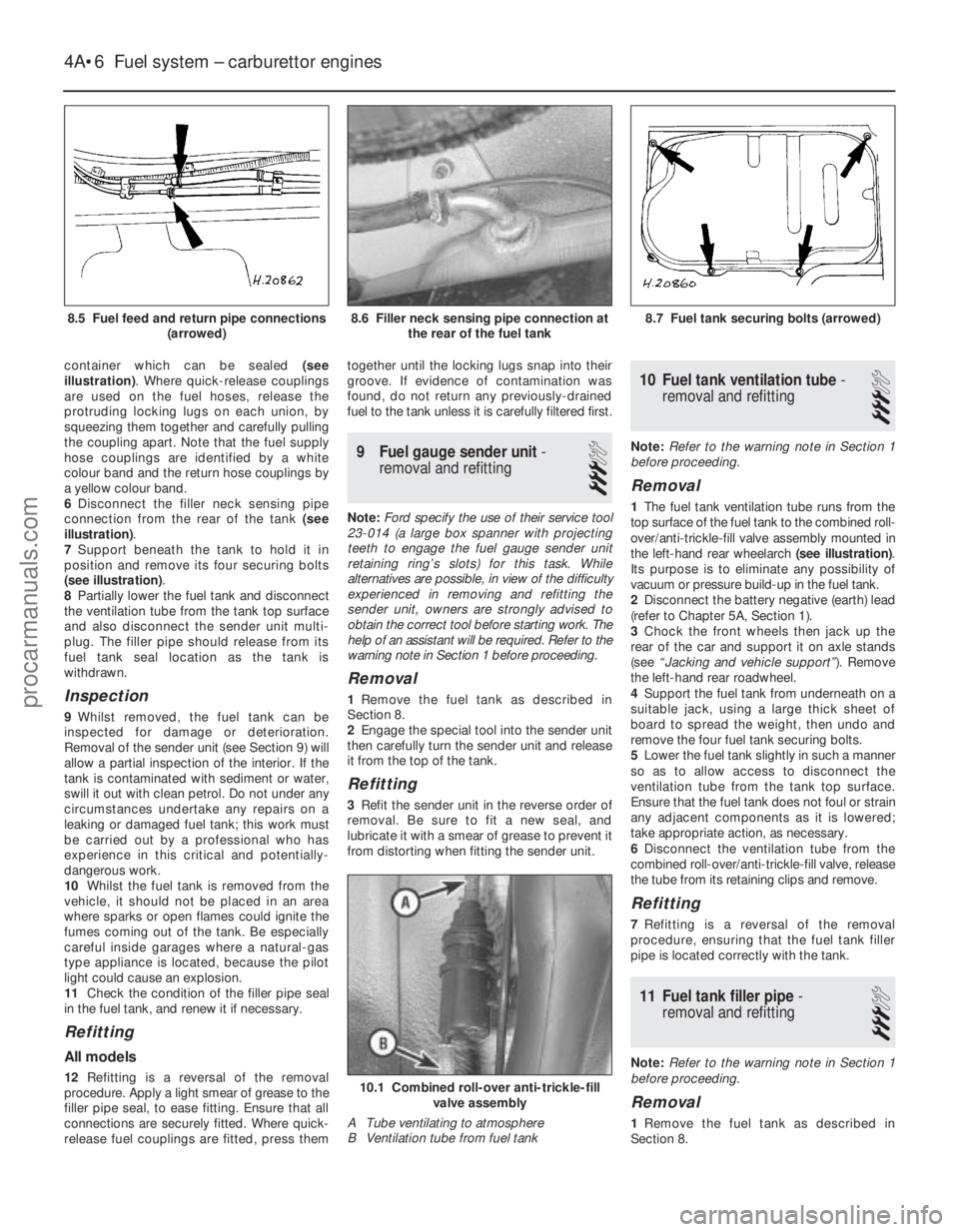
container which can be sealed (see
illustration) . Where quick-release couplings
are used on the fuel hoses, release the
protruding locking lugs on each union, by
squeezing them together and carefully pulling
the coupling apart. Note that the fuel supply
hose couplings are identified by a white
colour band and the return hose couplings by
a yellow colour band.
6 Disconnect the filler neck sensing pipe
connection from the rear of the tank (see
illustration) .
7 Support beneath the tank to hold it in
position and remove its four securing bolts
(see illustration) .
8 Partially lower the fuel tank and disconnect
the ventilation tube from the tank top surface
and also disconnect the sender unit multi-
plug. The filler pipe should release from its
fuel tank seal location as the tank is
withdrawn.
Inspection
9 Whilst removed, the fuel tank can be
inspected for damage or deterioration.
Removal of the sender unit (see Section 9) will
allow a partial inspection of the interior. If the
tank is contaminated with sediment or water,
swill it out with clean petrol. Do not under any
circumstances undertake any repairs on a
leaking or damaged fuel tank; this work must
be carried out by a professional who has
experience in this critical and potentially-
dangerous work.
10 Whilst the fuel tank is removed from the
vehicle, it should not be placed in an area
where sparks or open flames could ignite the
fumes coming out of the tank. Be especially
careful inside garages where a natural-gas
type appliance is located, because the pilot
light could cause an explosion.
11 Check the condition of the filler pipe seal
in the fuel tank, and renew it if necessary.
Refitting
All models
12 Refitting is a reversal of the removal
procedure. Apply a light smear of grease to the
filler pipe seal, to ease fitting. Ensure that all
connections are securely fitted. Where quick-
release fuel couplings are fitted, press them together until the locking lugs snap into their
groove. If evidence of contamination was
found, do not return any previously-drained
fuel to the tank unless it is carefully filtered first.
9
Fuel gauge sender unit -
removal and refitting
3
Note: Ford specify the use of their service tool
23-014 (a large box spanner with projecting
teeth to engage the fuel gauge sender unit
retaining ring’s slots) for this task. While
alternatives are possible, in view of the difficulty
experienced in removing and refitting the
sender unit, owners are strongly advised to
obtain the correct tool before starting work. The
help of an assistant will be required. Refer to the
warning note in Section 1 before proceeding.
Removal
1 Remove the fuel tank as described in
Section 8.
2 Engage the special tool into the sender unit
then carefully turn the sender unit and release
it from the top of the tank.
Refitting
3 Refit the sender unit in the reverse order of
removal. Be sure to fit a new seal, and
lubricate it with a smear of grease to prevent it
from distorting when fitting the sender unit.
10 Fuel tank ventilation tube -
removal and refitting
3
Note: Refer to the warning note in Section 1
before proceeding.
Removal
1 The fuel tank ventilation tube runs from the
top surface of the fuel tank to the combined roll-
over/anti-trickle-fill valve assembly mounted in
the left-hand rear wheelarch (see illustration).
Its purpose is to eliminate any possibility of
vacuum or pressure build-up in the fuel tank.
2 Disconnect the battery negative (earth) lead
(refer to Chapter 5A, Section 1).
3 Chock the front wheels then jack up the
rear of the car and support it on axle stands
(see “Jacking and vehicle support” ). Remove
the left-hand rear roadwheel.
4 Support the fuel tank from underneath on a
suitable jack, using a large thick sheet of
board to spread the weight, then undo and
remove the four fuel tank securing bolts.
5 Lower the fuel tank slightly in such a manner
so as to allow access to disconnect the
ventilation tube from the tank top surface.
Ensure that the fuel tank does not foul or strain
any adjacent components as it is lowered;
take appropriate action, as necessary.
6 Disconnect the ventilation tube from the
combined roll-over/anti-trickle-fill valve, release
the tube from its retaining clips and remove.
Refitting
7 Refitting is a reversal of the removal
procedure, ensuring that the fuel tank filler
pipe is located correctly with the tank.
11 Fuel tank filler pipe -
removal and refitting
3
Note: Refer to the warning note in Section 1
before proceeding.
Removal
1 Remove the fuel tank as described in
Section 8.
4A•6 Fuel system – carburettor engines
10.1 Combined roll-over anti-trickle-fill valve assembly
A Tube ventilating to atmosphere
B Ventilation tube from fuel tank
8.7 Fuel tank securing bolts (arrowed)8.6 Filler neck sensing pipe connection at the rear of the fuel tank
1595Ford Fiesta Remake
8.5 Fuel feed and return pipe connections
(arrowed)procarmanuals.com
http://vnx.su
Page 112 of 296
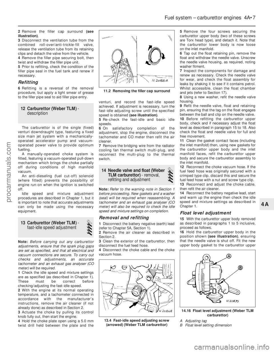
2Remove the filler cap surround (see
illustration) .
3 Disconnect the ventilation tube from the
combined roll-over/anti-trickle-fill valve,
release the ventilation tube from its retaining
clips and detach the valve from the vehicle.
4 Remove the filler pipe securing bolt, then
twist and withdraw the filler pipe unit.
5 Prior to refitting, check the condition of the
filler pipe seal in the fuel tank and renew if
necessary.
Refitting
6 Refitting is a reversal of the removal
procedure, but apply a light smear of grease
to the filler pipe seal to aid filler pipe entry.
12 Carburettor (Weber TLM) -
description
The carburettor is of the single (fixed)
venturi downdraught type, featuring a fixed
size main jet system with a mechanically-
operated accelerator pump and vacuum-
operated power valve to provide optimum
fuelling. A manually-operated choke system is
fitted, featuring a vacuum-operated pull-down
mechanism which brings the choke partially
off during conditions of high manifold
vacuum. An anti-dieseling (fuel cut-off) solenoid
(where fitted) prevents the possibility of
engine run-on when the ignition is switched
off. Idle speed and mixture adjustment
procedures are described in Chapter 1, but it
is important to note that accurate adjustments
can only be made using the necessary
equipment.
13 Carburettor (Weber TLM) -
fast-idle speed adjustment
4
Note: Before carrying out any carburettor
adjustments, ensure that the spark plug gaps
are set as specified, and that all electrical and
vacuum connections are secure. To carry out
checks and adjustments, an accurate
tachometer and an exhaust gas analyser (CO
meter) will be required.
1 Check the idle speed and mixture settings
are as specified (as described in Chapter 1).
These must be correct before
checking/adjusting the fast-idle speed.
2 With the engine at its normal operating
temperature, and a tachometer connected in
accordance with the manufacturer’s
instructions, remove the air cleaner (if not
already done) as described in Section 2.
3 Actuate the choke by pulling its control
knob fully out, then start the engine.
4 Hold the choke plate open using a 5.0 mm
twist drill held between the plate and the venturi, and record the fast-idle speed
achieved. If adjustment is necessary, turn the
fast-idle adjusting screw until the specified
speed is obtained
(see illustration).
5 Re-check the fast-idle and basic idle
speeds.
6 On satisfactory completion of the
adjustment, stop the engine, disconnect the
tachometer and CO meter then refit the air
cleaner.
7 Remove the bridging wire from the radiator
cooling fan thermal switch multi-plug, and
reconnect the multi-plug to the thermal
switch.
14 Needle valve and float (Weber
TLM carburettor) - removal,
refitting and adjustment
4
Note: Refer to the warning note in Section 1
before proceeding. New gaskets and a washer
(seal) will be required when reassembling. A
tachometer and an exhaust gas analyser (CO
meter) will also be required to check the idle
speed and mixture settings on completion.
Removal and refitting
1 Disconnect the battery negative (earth) lead
(refer to Chapter 5A, Section 1).
2 Remove the air cleaner as described in
Section 2.
3 Clean the exterior of the carburettor, then
disconnect the fuel feed hose.
4 Disconnect the choke cable and the choke
vacuum hose. 5
Remove the four screws securing the
carburettor upper body (two of these screws
are Torx head type), and detach it. Note that
the carburettor lower body is now loose
on the inlet manifold.
6 Tap out the float retaining pin, remove the
float and withdraw the needle valve. Unscrew
the needle valve housing, as required, noting
washer fitment.
7 Inspect the components for damage and
renew as necessary. Check the needle valve
for wear, and check the float assembly for
leaks by shaking it to see if it contains petrol.
Whilst accessible, clean the float chamber
and jets (refer to Section 17).
8 Using a new washer, refit the needle valve
housing.
9 Refit the needle valve, float and retaining
pin, ensuring that the tag on the float engages
between the ball and clip on the needle valve.
10 Before refitting the carburettor upper
body, check and if necessary adjust the float
level as described in paragraph 15 to 18. Also
check the float and needle valve for full and
free movement.
11 Clean the gasket contact faces (including
the inlet manifold) then, using new gaskets for
the carburettor upper body and the inlet
manifold faces, refit the carburettor upper
body and secure the carburettor assembly to
the inlet manifold.
12 Reconnect the choke vacuum hose. If the
fuel feed hose was originally secured with a
crimped type clip, discard this and secure the
fuel feed hose with a nut and screw type clip.
13 Reconnect and adjust the choke cable,
then refit the air cleaner.
14 Reconnect the battery negative lead, start
and warm up the engine then check the idle
speed and mixture settings as described in
Chapter 1.
Float level adjustment
15 With the carburettor upper body removed
as described in paragraphs 1 to 5 inclusive,
proceed as follows.
16 Hold the carburettor upper body in the
position shown (see illustration) , ensuring
that the needle valve is shut off. Fit the new
upper body gasket to the carburettor upper
Fuel system – carburettor engines 4A•7
13.4 Fast-idle speed adjusting screw (arrowed) (Weber TLM carburettor)
11.2 Removing the filler cap surround
14.16 Float level adjustment (Weber TLM carburettor)
A Adjusting tag
B Float level setting dimension
4A
1595Ford Fiesta Remakeprocarmanuals.com
http://vnx.su
Page 113 of 296
body, then measure the distance between the
gasket and the step on the float.
17If the measurement is not as specified,
adjust by bending the tag on the float, then re-
check.
18 Refitting should be carried out in
accordance with paragraphs 11 to 14
inclusive.
15 Carburettor (Weber TLM) -
removal and refitting
4
Note: Refer to the warning note in Section 1
before proceeding. New gaskets will be
required when reassembling. A tachometer
and an exhaust gas analyser (CO meter) will
also be required to check the idle speed and
mixture settings on completion.
Removal
1 Disconnect the battery negative (earth) lead
(refer to Chapter 5A, Section 1).
2 Remove the air cleaner as described in
Section 2.
3 Disconnect the accelerator inner and outer
cable from the carburettor (Section 3).
4 Disconnect the choke inner and outer cable
from the carburettor (Section 6).
5 Disconnect the fuel feed hose from the
carburettor, and plug its end to avoid spillage
and prevent dirt ingress. If a crimped type
hose clip is fitted, cut this free taking care to
avoid damage to the hose.
6 Where applicable, disconnect the electrical
lead from the anti-dieseling (fuel cut-off)
solenoid, and all relevant carburettor vacuum
pipes (having labelled them for correct
subsequent refitting).
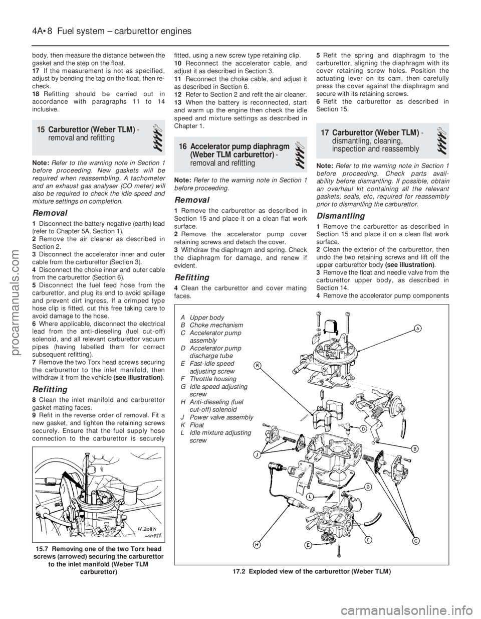
7 Remove the two Torx head screws securing
the carburettor to the inlet manifold, then
withdraw it from the vehicle (see illustration).
Refitting
8Clean the inlet manifold and carburettor
gasket mating faces.
9 Refit in the reverse order of removal. Fit a
new gasket, and tighten the retaining screws
securely. Ensure that the fuel supply hose
connection to the carburettor is securely fitted, using a new screw type retaining clip.
10
Reconnect the accelerator cable, and
adjust it as described in Section 3.
11 Reconnect the choke cable, and adjust it
as described in Section 6.
12 Refer to Section 2 and refit the air cleaner.
13 When the battery is reconnected, start
and warm up the engine then check the idle
speed and mixture settings as described in
Chapter 1.
16 Accelerator pump diaphragm (Weber TLM carburettor) -
removal and refitting
4
Note: Refer to the warning note in Section 1
before proceeding.
Removal
1 Remove the carburettor as described in
Section 15 and place it on a clean flat work
surface.
2 Remove the accelerator pump cover
retaining screws and detach the cover.
3 Withdraw the diaphragm and spring. Check
the diaphragm for damage, and renew if
evident.
Refitting
4 Clean the carburettor and cover mating
faces. 5
Refit the spring and diaphragm to the
carburettor, aligning the diaphragm with its
cover retaining screw holes. Position the
actuating lever on its cam, then carefully
press the cover against the diaphragm and
secure with its retaining screws.
6 Refit the carburettor as described in
Section 15.
17 Carburettor (Weber TLM) -
dismantling, cleaning,
inspection and reassembly
4
Note: Refer to the warning note in Section 1
before proceeding. Check parts avail-
ability before dismantling. If possible, obtain
an overhaul kit containing all the relevant
gaskets, seals, etc, required for reassembly
prior to dismantling the carburettor.
Dismantling
1 Remove the carburettor as described in
Section 15 and place it on a clean flat work
surface.
2 Clean the exterior of the carburettor, then
undo the two retaining screws and lift off the
upper carburettor body (see illustration).
3 Remove the float and needle valve from the
carburettor upper body, as described in
Section 14.
4 Remove the accelerator pump components
4A•8 Fuel system – carburettor engines
17.2 Exploded view of the carburettor (Weber TLM)
15.7 Removing one of the two Torx head
screws (arrowed) securing the carburettor to the inlet manifold (Weber TLM
carburettor)
1595Ford Fiesta Remake
A Upper body
B Choke mechanism
C Accelerator pump
assembly
D Accelerator pump discharge tube
E Fast-idle speed adjusting screw
F Throttle housing
G Idle speed adjusting screw
H Anti-dieseling (fuel cut-off) solenoid
J Power valve assembly
K Float
L Idle mixture adjusting screwprocarmanuals.com
http://vnx.su
Page 114 of 296
as described in Section 16. The power valve
assembly can also be removed in a similar
fashion.
5Prise free the accelerator pump discharge
tube, but take care not to damage it or the
carburettor body.
6 Remove the jets and emulsion tubes as
required, making careful notes of their
respective locations for reassembly.
Cleaning and inspection
7 Soak out the fuel in the float chamber using
a clean rag; this must be safely disposed of.
Clean the float chamber, jets, drillings and
passages with clean petrol. The careful use of
an air line (or footpump) is ideal to blow out
the upper and lower bodies. Never use a
piece of wire for cleaning purposes.
8 Examine all of the carburettor components
for signs of damage or wear, paying particular
attention to the diaphragms, throttle spindle
and plates, and needle valve. Renew all
diaphragms, sealing washers and gaskets as
a matter of course.
Reassembly
9 Refit the emulsion tubes and jets to their
locations as noted during dismantling.
10 Refit the accelerator pump discharge
tube.
11 Refit the accelerator pump and power
valve assemblies as described in Section 16.
12 Refit the needle valve and the float, and
adjust the float setting as described in Sec-
tion 14.
13 Locate a new gasket onto the mating
face, then refit the carburettor upper body to
the main body. As they are reassembled, take
care not to snag the float on the carburettor
main body. Fit and tighten the retaining
screws to secure.
14 On completion, refit the carburettor as
described in Section 15.
18 Carburettor (Weber TLDM) -
description
The carburettor is of twin venturi,
downdraught type, featuring a fixed size main
jet system, adjustable idle system, a
mechanically-operated accelerator pump, and
a vacuum-operated power valve. A manually-
operated cold start choke is fitted, and a
throttle kicker is used on certain models.
In order to comply with emission control
regulations and maintain good fuel
consumption, the main jets are calibrated to
suit the 1/4 to 3/4 throttle range. The power
valve is therefore only used to supply
additional fuel during full-throttle conditions. The accelerator pump is fitted to ensure a
smooth transmission from the idle circuit to
the main jet system. As the accelerator pedal
is depressed, a linkage moves the diaphragm
within the accelerator pump, and a small quantity of fuel is injected into the venturi, to
prevent a momentary weak mixture and
resultant engine hesitation.
The manually-operated choke features a
vacuum-operated pull-down mechanism
which controls the single choke plate under
certain vacuum conditions. On CTX automatic transmission models,
the throttle kicker acts as an idle speed
compensator for when the transmission shift
lever positions R, D or L are selected. The
throttle kicker is operated by vacuum supplied
from the inlet manifold. When the appropriate
transmission shift lever position is selected,
the throttle kicker control solenoid allows the
vacuum to pass to the throttle kicker which
maintains the idle speed by means of a
diaphragm and mechanical linkage. On manual transmission models, the
throttle kicker (when fitted) acts as a damper
by slowing down the closing action of the
throttle plate. Under deceleration, this
maintains the combustion of the air/fuel
mixture entering the cylinders, thus improving
the exhaust emission levels. A vacuum
sustain valve controls the carburettor-sourced
vacuum applied to the throttle kicker unit; this
allows the vacuum slowly to decay, allowing
normal engine idling speed to be achieved. An anti-dieseling (fuel cut-off) solenoid is
fitted to prevent the possibility of the engine
running on after the ignition is switched off. Idle speed and mixture adjustment
procedures are described in Chapter 1, but it
is important to note that accurate adjustments
can only be made using the necessary
equipment.
19 Carburettor (Weber TLDM) -
fast-idle speed adjustment
4
Note: Before carrying out any carburettor
adjustments, ensure that the spark plug gaps
are set as specified, and that all electrical and
vacuum connections are secure. To carry out
checks and adjustments, an accurate
tachometer and an exhaust gas analyser (CO
meter) will be required.
1 Check the idle speed and mixture settings are as specified (as described in Chapter 1).
These must be correct before
checking/adjusting the fast-idle speed.
2
With the engine at its normal operating
temperature, and a tachometer connected in
accordance with the manufacturer’s
instructions, switch the engine off, then
remove the air cleaner (if not already done) as
described in Section 2.
3 Actuate the choke by pulling the control
knob fully out, then start the engine and note
the engine fast-idle speed. Compare it with
the specified speed.
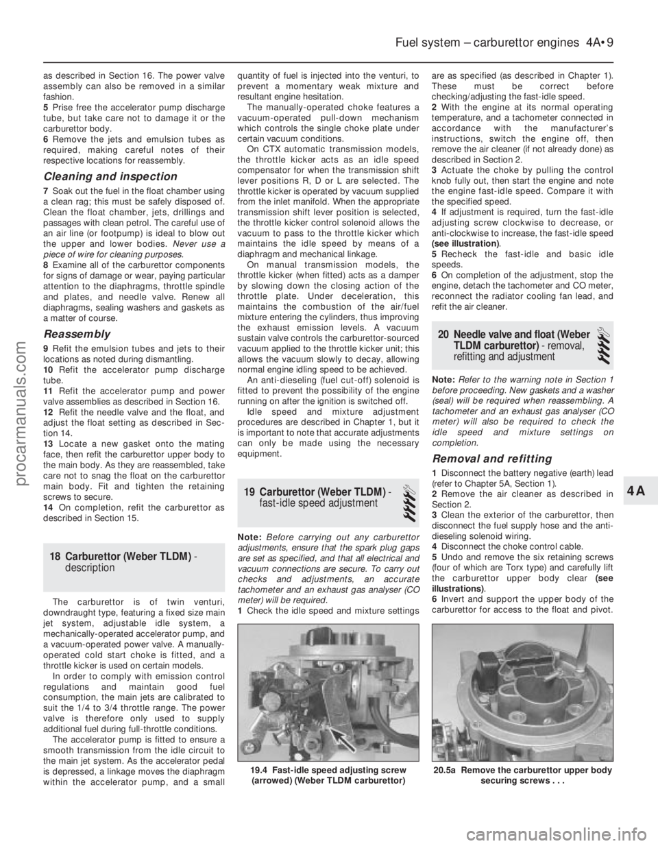
4 If adjustment is required, turn the fast-idle
adjusting screw clockwise to decrease, or
anti-clockwise to increase, the fast-idle speed
(see illustration) .
5 Recheck the fast-idle and basic idle
speeds.
6 On completion of the adjustment, stop the
engine, detach the tachometer and CO meter,
reconnect the radiator cooling fan lead, and
refit the air cleaner.
20 Needle valve and float (Weber
TLDM carburettor) - removal,
refitting and adjustment
4
Note: Refer to the warning note in Section 1
before proceeding. New gaskets and a washer
(seal) will be required when reassembling. A
tachometer and an exhaust gas analyser (CO
meter) will also be required to check the
idle speed and mixture settings on
completion.
Removal and refitting
1 Disconnect the battery negative (earth) lead
(refer to Chapter 5A, Section 1).
2 Remove the air cleaner as described in
Section 2.
3 Clean the exterior of the carburettor, then
disconnect the fuel supply hose and the anti-
dieseling solenoid wiring.
4 Disconnect the choke control cable.
5 Undo and remove the six retaining screws
(four of which are Torx type) and carefully lift
the carburettor upper body clear (see
illustrations) .
6 Invert and support the upper body of the
carburettor for access to the float and pivot.
Fuel system – carburettor engines 4A•9
19.4 Fast-idle speed adjusting screw (arrowed) (Weber TLDM carburettor)
4A
1595Ford Fiesta Remake
20.5a Remove the carburettor upper body securing screws . . .
procarmanuals.com
http://vnx.su
Page 115 of 296
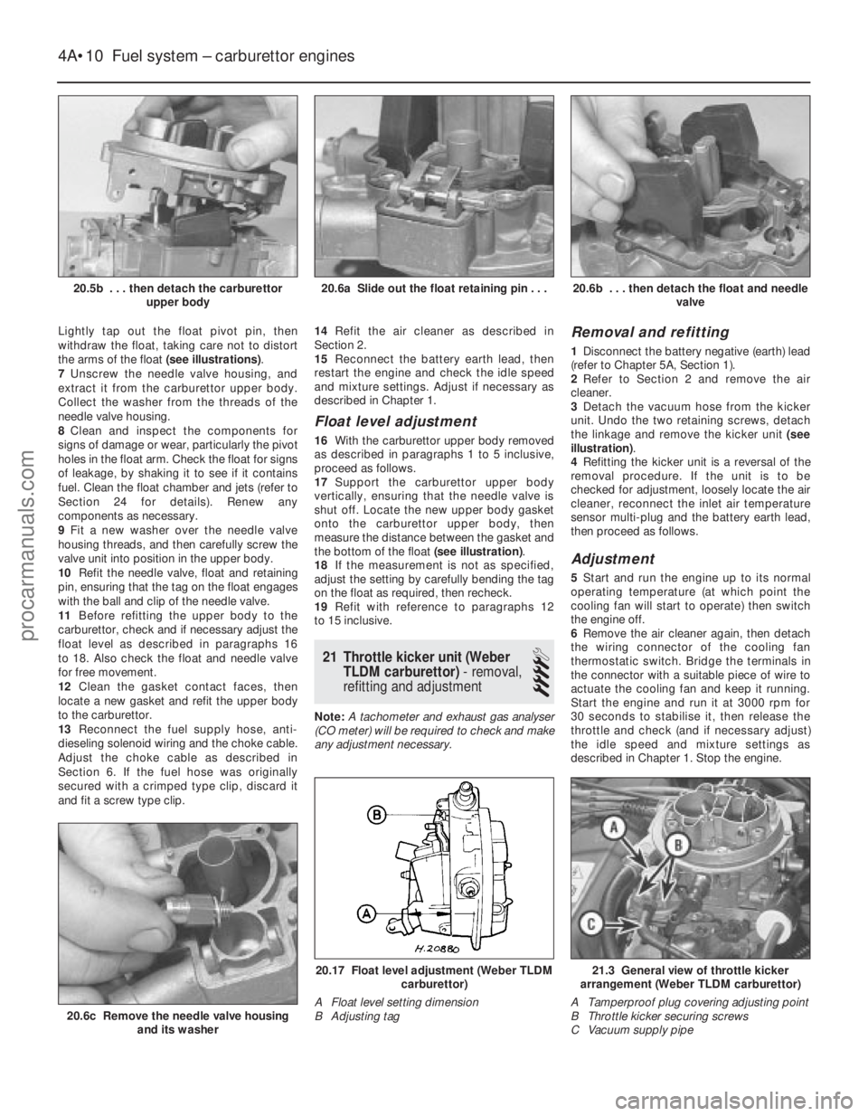
Lightly tap out the float pivot pin, then
withdraw the float, taking care not to distort
the arms of the float (see illustrations).
7 Unscrew the needle valve housing, and
extract it from the carburettor upper body.
Collect the washer from the threads of the
needle valve housing.
8 Clean and inspect the components for
signs of damage or wear, particularly the pivot
holes in the float arm. Check the float for signs
of leakage, by shaking it to see if it contains
fuel. Clean the float chamber and jets (refer to
Section 24 for details). Renew any
components as necessary.
9 Fit a new washer over the needle valve
housing threads, and then carefully screw the
valve unit into position in the upper body.
10 Refit the needle valve, float and retaining
pin, ensuring that the tag on the float engages
with the ball and clip of the needle valve.
11 Before refitting the upper body to the
carburettor, check and if necessary adjust the
float level as described in paragraphs 16
to 18. Also check the float and needle valve
for free movement.
12 Clean the gasket contact faces, then
locate a new gasket and refit the upper body
to the carburettor.
13 Reconnect the fuel supply hose, anti-
dieseling solenoid wiring and the choke cable.
Adjust the choke cable as described in
Section 6. If the fuel hose was originally
secured with a crimped type clip, discard it
and fit a screw type clip. 14
Refit the air cleaner as described in
Section 2.
15 Reconnect the battery earth lead, then
restart the engine and check the idle speed
and mixture settings. Adjust if necessary as
described in Chapter 1.
Float level adjustment
16 With the carburettor upper body removed
as described in paragraphs 1 to 5 inclusive,
proceed as follows.
17 Support the carburettor upper body
vertically, ensuring that the needle valve is
shut off. Locate the new upper body gasket
onto the carburettor upper body, then
measure the distance between the gasket and
the bottom of the float (see illustration).
18 If the measurement is not as specified,
adjust the setting by carefully bending the tag
on the float as required, then recheck.
19 Refit with reference to paragraphs 12
to 15 inclusive.
21 Throttle kicker unit (Weber TLDM carburettor) - removal,
refitting and adjustment
4
Note: A tachometer and exhaust gas analyser
(CO meter) will be required to check and make
any adjustment necessary.
Removal and refitting
1 Disconnect the battery negative (earth) lead
(refer to Chapter 5A, Section 1).
2 Refer to Section 2 and remove the air
cleaner.
3 Detach the vacuum hose from the kicker
unit. Undo the two retaining screws, detach
the linkage and remove the kicker unit (see
illustration) .
4 Refitting the kicker unit is a reversal of the
removal procedure. If the unit is to be
checked for adjustment, loosely locate the air
cleaner, reconnect the inlet air temperature
sensor multi-plug and the battery earth lead,
then proceed as follows.
Adjustment
5 Start and run the engine up to its normal
operating temperature (at which point the
cooling fan will start to operate) then switch
the engine off.
6 Remove the air cleaner again, then detach
the wiring connector of the cooling fan
thermostatic switch. Bridge the terminals in
the connector with a suitable piece of wire to
actuate the cooling fan and keep it running.
Start the engine and run it at 3000 rpm for
30 seconds to stabilise it, then release the
throttle and check (and if necessary adjust)
the idle speed and mixture settings as
described in Chapter 1. Stop the engine.
4A•10 Fuel system – carburettor engines
21.3 General view of throttle kicker
arrangement (Weber TLDM carburettor)
A Tamperproof plug covering adjusting point
B Throttle kicker securing screws
C Vacuum supply pipe20.17 Float level adjustment (Weber TLDM carburettor)
A Float level setting dimension
B Adjusting tag
20.6c Remove the needle valve housing and its washer
20.6b . . . then detach the float and needle valve20.6a Slide out the float retaining pin . . .20.5b . . . then detach the carburettorupper body
1595Ford Fiesta Remakeprocarmanuals.com
http://vnx.su
Page 116 of 296
7Detach the vacuum hose between the
throttle kicker and the inlet manifold at source
(but not the vacuum supply to the ignition
module). Connect a new length of vacuum
hose directly between the manifold and the
kicker unit.
8 Restart the engine and check the engine
speed. The throttle kicker should increase the
engine speed above its normal idle. Check the
speed registered against the specified throttle
kicker operating speed.
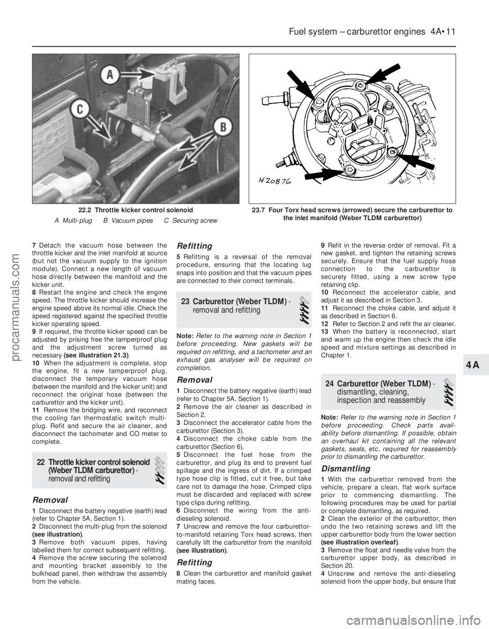
9 If required, the throttle kicker speed can be
adjusted by prising free the tamperproof plug
and the adjustment screw turned as
necessary (see illustration 21.3) .
10 When the adjustment is complete, stop
the engine, fit a new tamperproof plug,
disconnect the temporary vacuum hose
(between the manifold and the kicker unit) and
reconnect the original hose (between the
carburettor and the kicker unit).
11 Remove the bridging wire, and reconnect
the cooling fan thermostatic switch multi-
plug. Refit and secure the air cleaner, and
disconnect the tachometer and CO meter to
complete.
22 Throttle kicker control solenoid
(Weber TLDM carburettor) -
removal and refitting
2
Removal
1 Disconnect the battery negative (earth) lead
(refer to Chapter 5A, Section 1).
2 Disconnect the multi-plug from the solenoid
(see illustration) .
3 Remove both vacuum pipes, having
labelled them for correct subsequent refitting.
4 Remove the screw securing the solenoid
and mounting bracket assembly to the
bulkhead panel, then withdraw the assembly
from the vehicle.
Refitting
5 Refitting is a reversal of the removal
procedure, ensuring that the locating lug
snaps into position and that the vacuum pipes
are connected to their correct terminals.
23 Carburettor (Weber TLDM) -
removal and refitting
4
Note: Refer to the warning note in Section 1
before proceeding. New gaskets will be
required on refitting, and a tachometer and an
exhaust gas analyser will be required on
completion.
Removal
1 Disconnect the battery negative (earth) lead
(refer to Chapter 5A, Section 1).
2 Remove the air cleaner as described in
Section 2.
3 Disconnect the accelerator cable from the
carburettor (Section 3).
4 Disconnect the choke cable from the
carburettor (Section 6).
5 Disconnect the fuel hose from the
carburettor, and plug its end to prevent fuel
spillage and the ingress of dirt. If a crimped
type hose clip is fitted, cut it free, but take
care not to damage the hose. Crimped clips
must be discarded and replaced with screw
type clips during refitting.
6 Disconnect the wiring from the anti-
dieseling solenoid.
7 Unscrew and remove the four carburettor-
to-manifold retaining Torx head screws, then
carefully lift the carburettor from the manifold
(see illustration) .
Refitting
8Clean the carburettor and manifold gasket
mating faces. 9
Refit in the reverse order of removal. Fit a
new gasket, and tighten the retaining screws
securely. Ensure that the fuel supply hose
connection to the carburettor is
securely fitted, using a new screw type
retaining clip.
10 Reconnect the accelerator cable, and
adjust it as described in Section 3.
11 Reconnect the choke cable, and adjust it
as described in Section 6.
12 Refer to Section 2 and refit the air cleaner.
13 When the battery is reconnected, start
and warm up the engine then check the idle
speed and mixture settings as described in
Chapter 1.
24 Carburettor (Weber TLDM) -
dismantling, cleaning,
inspection and reassembly
4
Note: Refer to the warning note in Section 1
before proceeding. Check parts avail-
ability before dismantling. If possible, obtain
an overhaul kit containing all the relevant
gaskets, seals, etc, required for reassembly
prior to dismantling the carburettor.
Dismantling
1 With the carburettor removed from the
vehicle, prepare a clean, flat work surface
prior to commencing dismantling. The
following procedures may be used for partial
or complete dismantling, as required.
2 Clean the exterior of the carburettor, then
undo the two retaining screws and lift the
upper carburettor body from the lower section
(see illustration overleaf) .
3 Remove the float and needle valve from the
carburettor upper body, as described in
Section 20.
4 Unscrew and remove the anti-dieseling
solenoid from the upper body, but ensure that
Fuel system – carburettor engines 4A•11
23.7 Four Torx head screws (arrowed) secure the carburettor to the inlet manifold (Weber TLDM carburettor)22.2 Throttle kicker control solenoid
A Multi-plug B Vacuum pipes C Securing screw
4A
1595Ford Fiesta Remakeprocarmanuals.com
http://vnx.su
Page 117 of 296
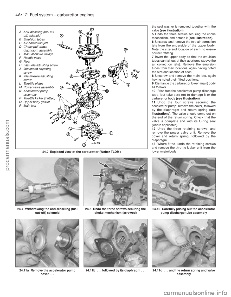
the seal washer is removed together with the
valve (see illustration) .
5 Undo the three screws securing the choke
mechanism, and detach it (see illustration).
6 Unscrew and remove the two air correction
jets from the underside of the upper body.
Note the size and location of each, to ensure
correct refitting.
7 Invert the upper body so that the emulsion
tubes can fall out of their apertures (above the
air correction jets). Remove the emulsion
tubes from their locations, again having noted
the size and location of each.
8 Unscrew and remove the main jets, again
having noted their fitted positions.
9 Dismantle the carburettor lower (main) body
as follows.
10 Prise free the accelerator pump discharge
tube, but take care not to damage it or the
carburettor body (see illustration).
11 Undo the four screws securing the
accelerator pump; remove the cover, followed
by the diaphragm and return spring (see
illustrations) . The valve should come out on
the end of the return spring. Check that the
valve is complete and with its O-ring seal
(where applicable).
12 Undo the three retaining screws, and
remove the power valve unit. Remove the
cover and return spring, followed by the
diaphragm.
13 Where fitted, undo the retaining screws
and remove the throttle kicker unit from the
lower (main) body.
4A•12 Fuel system – carburettor engines
24.11c . . . and the return spring and valve assembly24.11b . . . followed by its diaphragm . . .24.11a Remove the accelerator pumpcover . . .
24.10 Carefully prising out the accelerator
pump discharge tube assembly24.5 Undo the three screws securing the choke mechanism (arrowed)24.4 Withdrawing the anti-dieseling (fuel cut-off) solenoid
1595Ford Fiesta Remake
24.2 Exploded view of the carburettor (Weber TLDM)
A Anti-dieseling (fuel cut-off) solenoid
B Emulsion tubes
C Air-correction jets
D Choke pull-down diaphragm assembly
E Manual choke linkage
F Needle valve
G Float
H Fast-idle adjusting screw
J Idle speed adjusting screw
K Idle mixture adjusting screw
L Throttle plates
M Power valve assembly
N Accelerator pump assembly
P Throttle kicker (if fitted)
Q Upper body gasket
R Main jets
procarmanuals.com
http://vnx.su
Page 118 of 296
14Prise free and remove the tamperproof
seal, then unscrew and remove the idle
mixture adjustment screw.
15 Undo the retaining screws, and remove
the throttle housing from the carburettor main
body.
Cleaning and inspection
16 Wash the carburettor components,
drillings and passages with clean petrol, then
blow them dry using a low-pressure air line. A
high-pressure air line must not be applied to
the accelerator pump discharge assembly or
the pump supply valve, as they each contain a
rubber Vernay valve, and these can easily be
damaged under high pressure. Never use a
piece of wire for cleaning purposes.
17 Examine all of the carburettor
components for signs of damage or wear,
paying particular attention to the diaphragms,
throttle spindle and plates, needle valve and
mixture screw; the power valve jet is adjacent
to the primary main jet. Renew all
diaphragms, sealing washers and gaskets as
a matter of course.
Reassembly
18 Refit the throttle housing to the
carburettor main body (fitting a new gasket),
and secure with its retaining screws.
19 Refit the idle mixture adjustment screw.
Make an initial adjustment by screwing it fully
in (but do not overtighten or screw it onto its
seat), then unscrew it two full turns.
20 Where fitted, reassemble the throttle
kicker, ensuring that its diaphragm lies flat,
and that the relative position of the operating
link to the kicker cover is correct.
21 Fit the power valve, ensuring that its
diaphragm lies flat and the vacuum
gallery aligns with the diaphragm and
housing.
22 Refit the accelerator pump. Take care not
damage the valve as it is inserted, and check
that the O-ring seal is correctly located on the
end of the valve. Check that the valve is not
trapped by the spring.
23 Refit the accelerator pump discharge jet.
Take care not to damage the valve and/or the
O-ring seal, and ensure that they are correctly
located.
24 Commence reassembly of the upper body
by inserting the emulsion tubes and the air
correction jets into their respective ports (as
noted during removal).
25 Screw the anti-dieseling solenoid into
position. Ensure that the aluminium washer is
fitted, and take care not to overtighten the
valve.
26 Refit the needle valve and the float, and
adjust the float setting as described in Sec-
tion 20.
27 Refit the choke control mechanism, and
secure with its three retaining screws.
28 Locate a new gasket onto the mating
face, then refit the carburettor upper body to
the main body. As they are reassembled, take
care not to snag the float on the carburettor main body. Fit and tighten the retaining
screws to secure.
29
On completion, refit the carburettor as
described in Section 23. Where applicable,
check and adjust the throttle kicker setting
(Section 21) after adjusting the idle speed and
mixture settings.
25 Carburettor (Weber DFTM) -
description
The carburettor operates in essentially the
same manner as TLDM instrument described
in Section 18, but the following features
should be noted. A throttle kicker is fitted to both manual
transmission, and CTX automatic trans-
mission models, the operation of the unit is
described in Section 18. The secondary venturi (barrel) is vacuum-
operated on manual transmission models. On
CTX automatic transmission equipped models
it is operated sequentially. A bleed back solenoid (if fitted) is used to
control the amount of fuel being delivered to
the venturi by the action of the accelerator
pump. Idle speed and mixture adjustment
procedures are described in Chapter 1, but it
is important to note that accurate adjustments
can only be made using the necessary
equipment.
26 Carburettor (Weber DFTM) -
fast-idle speed adjustment
4
Refer to the procedure contained in Sec-
tion 19, but note the following points:
a) When removing the air cleaner, do not disconnect the vacuum supply or
crankcase ventilation hoses; the air
cleaner should be positioned clear of the
carburettor assembly.
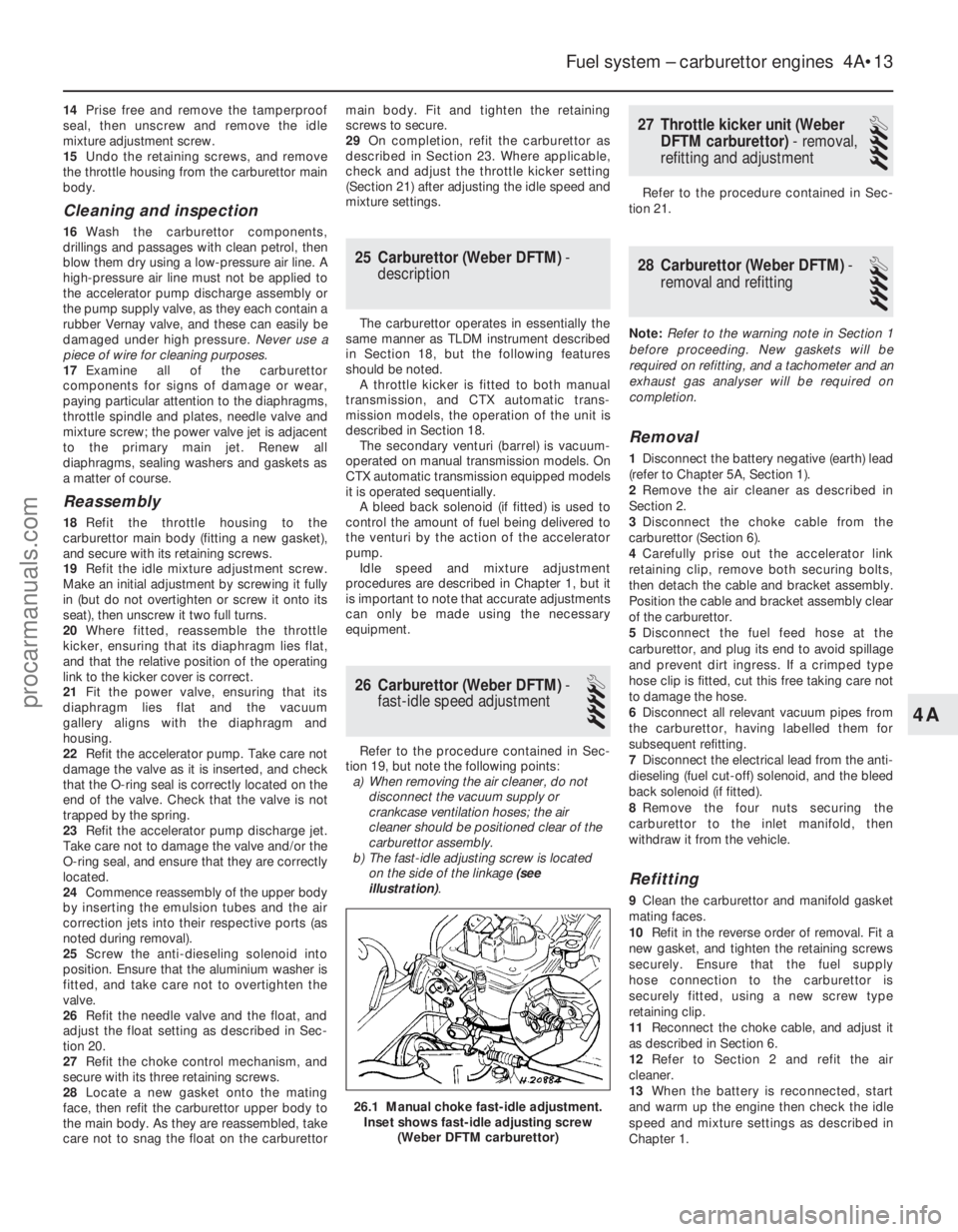
b) The fast-idle adjusting screw is located
on the side of the linkage (see
illustration) .
27 Throttle kicker unit (Weber
DFTM carburettor) - removal,
refitting and adjustment
4
Refer to the procedure contained in Sec-
tion 21.
28 Carburettor (Weber DFTM) -
removal and refitting
4
Note: Refer to the warning note in Section 1
before proceeding. New gaskets will be
required on refitting, and a tachometer and an
exhaust gas analyser will be required on
completion.
Removal
1 Disconnect the battery negative (earth) lead
(refer to Chapter 5A, Section 1).
2 Remove the air cleaner as described in
Section 2.
3 Disconnect the choke cable from the
carburettor (Section 6).
4 Carefully prise out the accelerator link
retaining clip, remove both securing bolts,
then detach the cable and bracket assembly.
Position the cable and bracket assembly clear
of the carburettor.
5 Disconnect the fuel feed hose at the
carburettor, and plug its end to avoid spillage
and prevent dirt ingress. If a crimped type
hose clip is fitted, cut this free taking care not
to damage the hose.
6 Disconnect all relevant vacuum pipes from
the carburettor, having labelled them for
subsequent refitting.
7 Disconnect the electrical lead from the anti-
dieseling (fuel cut-off) solenoid, and the bleed
back solenoid (if fitted).
8 Remove the four nuts securing the
carburettor to the inlet manifold, then
withdraw it from the vehicle.
Refitting
9 Clean the carburettor and manifold gasket
mating faces.
10 Refit in the reverse order of removal. Fit a
new gasket, and tighten the retaining screws
securely. Ensure that the fuel supply
hose connection to the carburettor is
securely fitted, using a new screw type
retaining clip.
11 Reconnect the choke cable, and adjust it
as described in Section 6.
12 Refer to Section 2 and refit the air
cleaner.
13 When the battery is reconnected, start
and warm up the engine then check the idle
speed and mixture settings as described in
Chapter 1.
Fuel system – carburettor engines 4A•13
26.1 Manual choke fast-idle adjustment. Inset shows fast-idle adjusting screw (Weber DFTM carburettor)
4A
1595Ford Fiesta Remakeprocarmanuals.com
http://vnx.su
Page 119 of 296
29 Carburettor (Weber DFTM)-
dismantling, cleaning,
inspection and reassembly
4
Note: Refer to the warning note in Section 1
before proceeding. Check parts avail-
ability before dismantling. If possible, obtain
an overhaul kit containing all the relevant
gaskets, seals, etc, required for reassembly
prior to dismantling the carburettor.
Dismantling
1 With the carburettor removed from the vehicle, prepare a clean, flat work surface
prior to commencing dismantling. The
following procedures may be used for partial
or complete dismantling, as required.
2
Clean the exterior of the carburettor and
detach all vacuum pipes (where applicable),
having noted their fitted location for correct
subsequent reassembly.
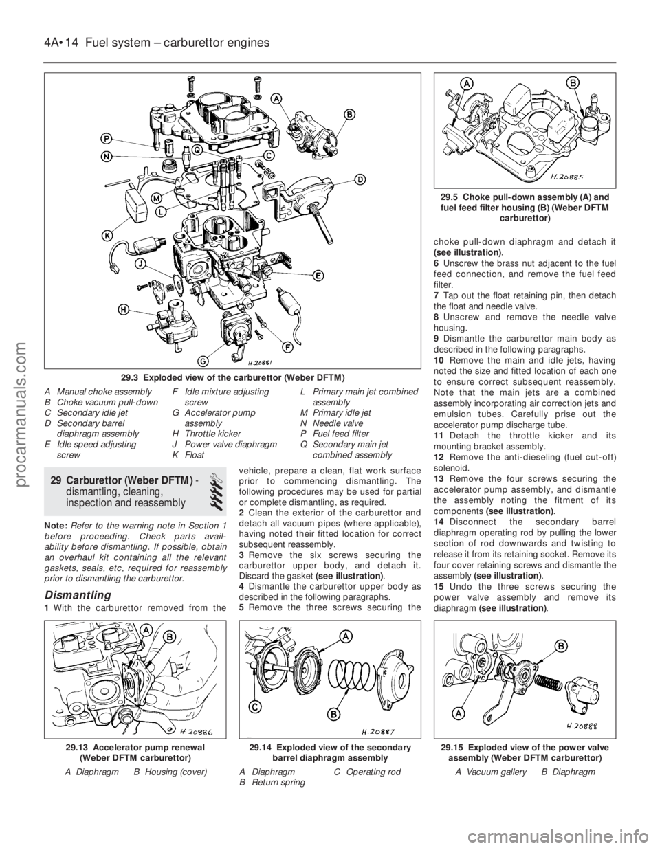
3 Remove the six screws securing the
carburettor upper body, and detach it.
Discard the gasket (see illustration).
4 Dismantle the carburettor upper body as
described in the following paragraphs.
5 Remove the three screws securing the choke pull-down diaphragm and detach it
(see illustration)
.
6 Unscrew the brass nut adjacent to the fuel
feed connection, and remove the fuel feed
filter.
7 Tap out the float retaining pin, then detach
the float and needle valve.
8 Unscrew and remove the needle valve
housing.
9 Dismantle the carburettor main body as
described in the following paragraphs.
10 Remove the main and idle jets, having
noted the size and fitted location of each one
to ensure correct subsequent reassembly.
Note that the main jets are a combined
assembly incorporating air correction jets and
emulsion tubes. Carefully prise out the
accelerator pump discharge tube.
11 Detach the throttle kicker and its
mounting bracket assembly.
12 Remove the anti-dieseling (fuel cut-off)
solenoid.
13 Remove the four screws securing the
accelerator pump assembly, and dismantle
the assembly noting the fitment of its
components (see illustration) .
14 Disconnect the secondary barrel
diaphragm operating rod by pulling the lower
section of rod downwards and twisting to
release it from its retaining socket. Remove its
four cover retaining screws and dismantle the
assembly (see illustration) .
15 Undo the three screws securing the
power valve assembly and remove its
diaphragm (see illustration) .
4A•14 Fuel system – carburettor engines
29.15 Exploded view of the power valve
assembly (Weber DFTM carburettor)
A Vacuum gallery B Diaphragm29.14 Exploded view of the secondary barrel diaphragm assembly
A Diaphragm C Operating rod
B Return spring29.13 Accelerator pump renewal (Weber DFTM carburettor)
A Diaphragm B Housing (cover)
29.5 Choke pull-down assembly (A) and fuel feed filter housing (B) (Weber DFTM carburettor)
29.3 Exploded view of the carburettor (Weber DFTM)
A Manual choke assembly
B Choke vacuum pull-down
C Secondary idle jet
D Secondary barreldiaphragm assembly
E Idle speed adjusting
screw F Idle mixture adjusting
screw
G Accelerator pump
assembly
H Throttle kicker
J Power valve diaphragm
K Float L Primary main jet combined
assembly
M Primary idle jet
N Needle valve
P Fuel feed filter
Q Secondary main jet
combined assembly
1595Ford Fiesta Remakeprocarmanuals.com
http://vnx.su
Page 120 of 296
16Prise out the tamperproof seal covering
the fuel mixture screw, then undo and remove
the mixture screw.
Cleaning and inspection
17 Wash the carburettor components,
drillings and passages with clean petrol, then
blow them dry using a low-pressure air line. A
high-pressure air line must not be applied to
the accelerator pump discharge assembly or
the pump supply valve, as they each contain a
rubber Vernay valve, and these can easily be
damaged under high pressure. Never use a
piece of wire for cleaning purposes.
18 Examine all of the carburettor
components for signs of damage or wear,
paying particular attention to the diaphragms,
throttle spindle and plates, needle valve and
mixture screw; the power valve jet is adjacent
to the primary main jet. Renew all
diaphragms, sealing washers and gaskets as
a matter of course.
Reassembly
19 Refit the fuel mixture screw by fully
winding the screw in, then unwinding three
turns to give an approximate setting.
20 Refit the power valve assembly ensuring
that the diaphragm lies flat, and that the
vacuum gallery lines up correctly with the
diaphragm and housing.
21 Reassemble the secondary barrel
diaphragm into its housing, ensuring that
the diaphragm lies flat and that the vacuum
gallery lines up with the diaphragm and
housing. Also, to assist with installation, do
not reconnect its operating rod until the cover
has been secured.
22 Refit the throttle kicker mounting bracket.
23 Refit the anti-dieseling (fuel cut-off)
solenoid, using a new sealing washer.
24 Refit the accelerator pump assembly,
ensuring that the diaphragm lies flat and is not
kinked.
25 Reassemble the throttle kicker, ensuring
that the diaphragm lies flat and that the relative position of the diaphragm operating
link to the throttle kicker cover is correct. Fully
attach the throttle kicker assembly.
26
Refit the main and idle jets, making
reference to the notes taken during
dismantling to ensure correct fitted locations.
27 Reassemble the carburettor upper body
as described in the following paragraphs.
28 Refit the needle valve housing (using a
new washer if applicable).
29 Refit the needle valve and float assembly,
having ensured that the float tag locates
below the spring clip on the needle valve.
Insert the float retaining pin to secure.
30 Adjust the float level as follows. Ensuring
that a new gasket is fitted to the carburettor
upper body, hold the upper body in the
vertical position; the needle valve must be
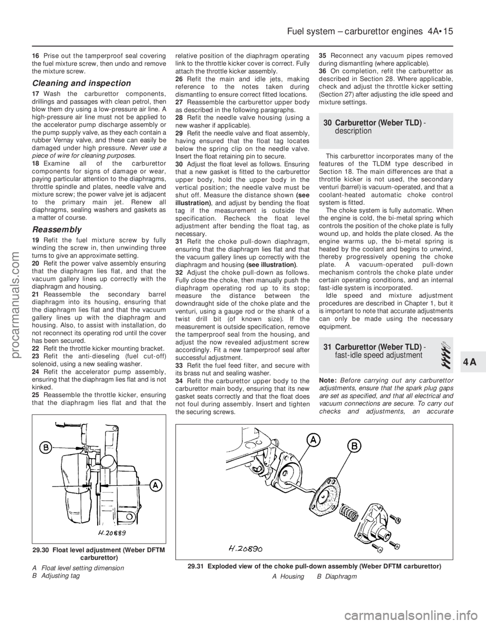
shut off. Measure the distance shown (see
illustration) , and adjust by bending the float
tag if the measurement is outside the
specification. Recheck the float level
adjustment after bending the float tag, as
necessary.
31 Refit the choke pull-down diaphragm,
ensuring that the diaphragm lies flat and that
the vacuum gallery lines up correctly with the
diaphragm and housing (see illustration).
32 Adjust the choke pull-down as follows.
Fully close the choke, then manually push the
diaphragm operating rod up to its stop;
measure the distance between the
downdraught side of the choke plate and the
venturi, using a gauge rod or the shank of a
twist drill bit (of known size). If the
measurement is outside specification, remove
the tamperproof seal from the housing, and
adjust the now revealed adjustment screw
accordingly. Fit a new tamperproof seal after
successful adjustment.
33 Refit the fuel feed filter, and secure with
its brass nut and sealing washer.
34 Refit the carburettor upper body to the
carburettor main body, ensuring that its new
gasket seats correctly and that the float does
not foul during assembly. Insert and tighten
the securing screws. 35
Reconnect any vacuum pipes removed
during dismantling (where applicable).
36 On completion, refit the carburettor as
described in Section 28. Where applicable,
check and adjust the throttle kicker setting
(Section 27) after adjusting the idle speed and
mixture settings.
30 Carburettor (Weber TLD) -
description
This carburettor incorporates many of the
features of the TLDM type described in
Section 18. The main differences are that a
throttle kicker is not used, the secondary
venturi (barrel) is vacuum-operated, and that a
coolant-heated automatic choke control
system is fitted. The choke system is fully automatic. When
the engine is cold, the bi-metal spring which
controls the position of the choke plate is fully
wound up, and holds the plate closed. As the
engine warms up, the bi-metal spring is
heated by the coolant and begins to unwind,
thereby progressively opening the choke
plate. A vacuum-operated pull-down
mechanism controls the choke plate under
certain operating conditions, and an internal
fast-idle system is incorporated. Idle speed and mixture adjustment
procedures are described in Chapter 1, but it
is important to note that accurate adjustments
can only be made using the necessary
equipment.
31 Carburettor (Weber TLD) -
fast-idle speed adjustment
4
Note: Before carrying out any carburettor
adjustments, ensure that the spark plug gaps
are set as specified, and that all electrical and
vacuum connections are secure. To carry out
checks and adjustments, an accurate
Fuel system – carburettor engines 4A•15
29.31 Exploded view of the choke pull-down assembly (Weber DFTM carbur\
ettor)
A Housing B Diaphragm
29.30 Float level adjustment (Weber DFTMcarburettor)
A Float level setting dimension
B Adjusting tag
4A
1595Ford Fiesta Remakeprocarmanuals.com
http://vnx.su