sensor FORD FIESTA 2007 Workshop Manual
[x] Cancel search | Manufacturer: FORD, Model Year: 2007, Model line: FIESTA, Model: FORD FIESTA 2007Pages: 1226, PDF Size: 61.26 MB
Page 726 of 1226
303-01 B-I 04 Engine - 2.OL Duratec-HE (M14) 303-01 B-I 04
ASSEMBLY
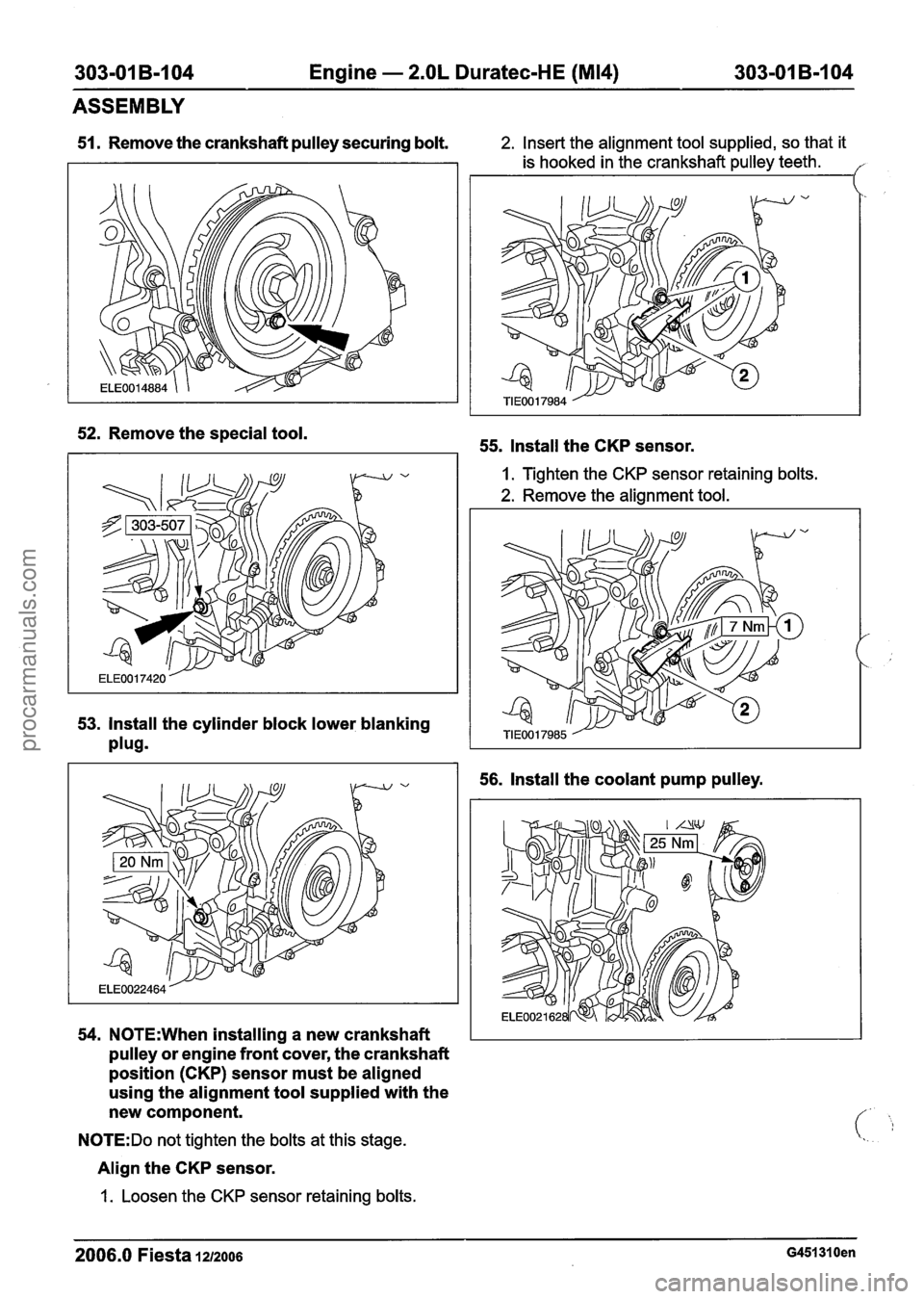
51. Remove the crankshaft pulley securing bolt. 2. Insert the alignment tool supplied, so that it
is hooked in the crankshaft pulley teeth.
I
52. Remove the special tool.
53. Install the cylinder block lower blanking
plug9
54. N0TE:When installing a new crankshaft
pulley or engine front cover, the crankshaft
position
(CKP) sensor must be aligned
using the alignment tool supplied with the
new component.
N0TE:Do not tighten the bolts at this stage.
Align the CKP sensor.
1.
Loosen the CKP sensor retaining bolts.
55. Install the CKP sensor.
I. Tighten the CKP sensor retaining bolts.
2. Remove the alignment tool.
56. Install the coolant pump pulley.
2006.0 Fiesta 1212006 G451310en
procarmanuals.com
Page 729 of 1226
303-01 B-107 Engine - 2.OL Duratec-HE (M14) 303-01 B-107
ASSEMBLY
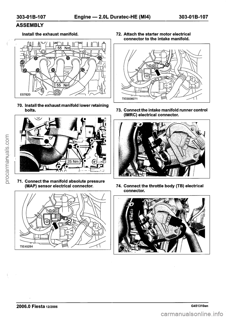
Install the exhaust manifold.
i
72. Attach the starter motor electrical
connector to the intake manifold.
70, Install the exhaust manifold lower retaining
bolts.
73. Connect the intake manifold runner control
(IMRC) electrical connector.
71. Connect the manifold absolute pressure
(MAP) sensor electrical connector. 74.
Connect the throttle body
(TB) electrical
connector.
2006.0 Fiesta 1212006 G451310en
procarmanuals.com
Page 730 of 1226
303-01 B-I08 Engine - 2.OL Duratec-HE (M14) 303-01 B-108
ASSEMBLY
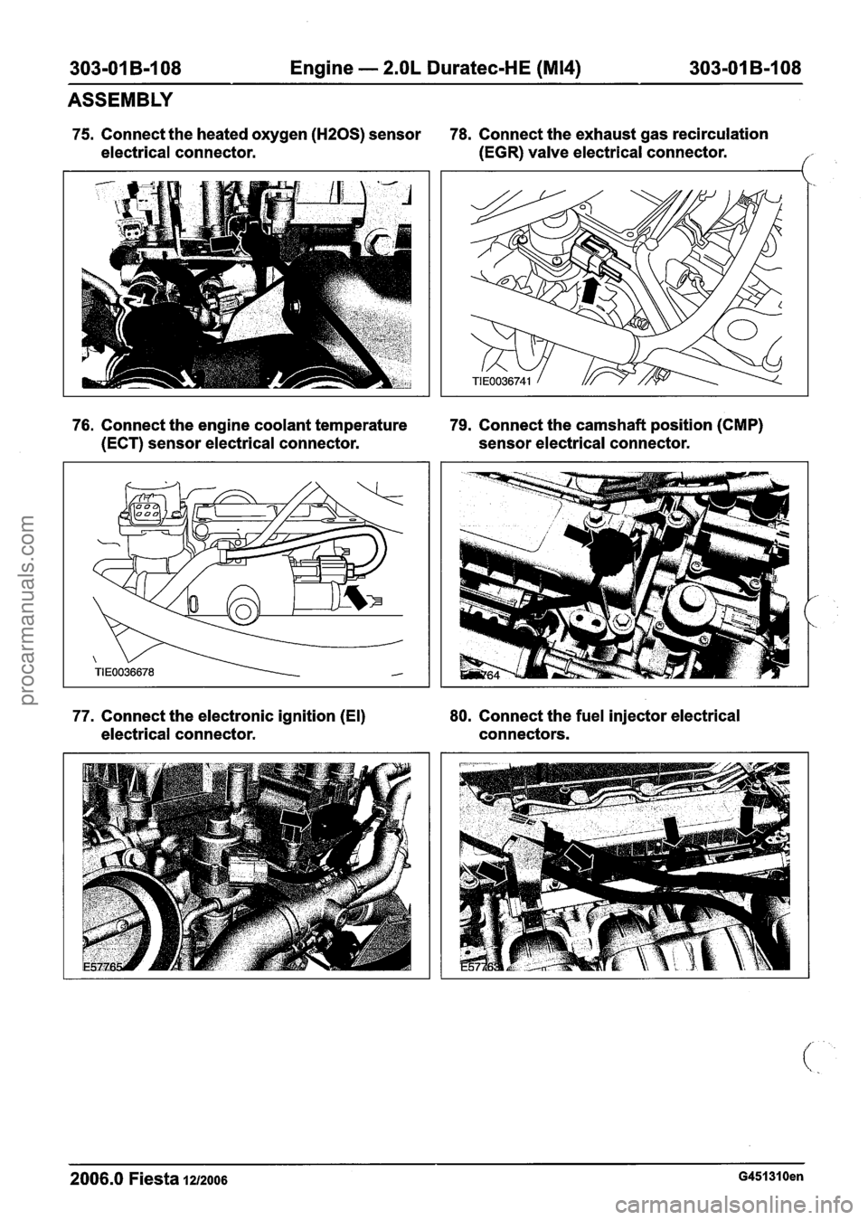
75. Connect the heated oxygen (HZOS) sensor 78. Connect the exhaust gas recirculation
electrical connector. (EGR)
valve electrical connector.
('
76. Connect the engine coolant temperature 79. Connect the camshaft position (CMP)
(ECT) sensor electrical connector. sensor electrical connector.
77. Connect the electronic ignition (El) 80.
Connect the fuel injector electrical
electrical connector. connectors.
2006.0 Fiesta 1212006 G451310en
procarmanuals.com
Page 731 of 1226
303-01 B-I 09 Engine - 2.OL Duratec-HE (M14) 303-01 B-109
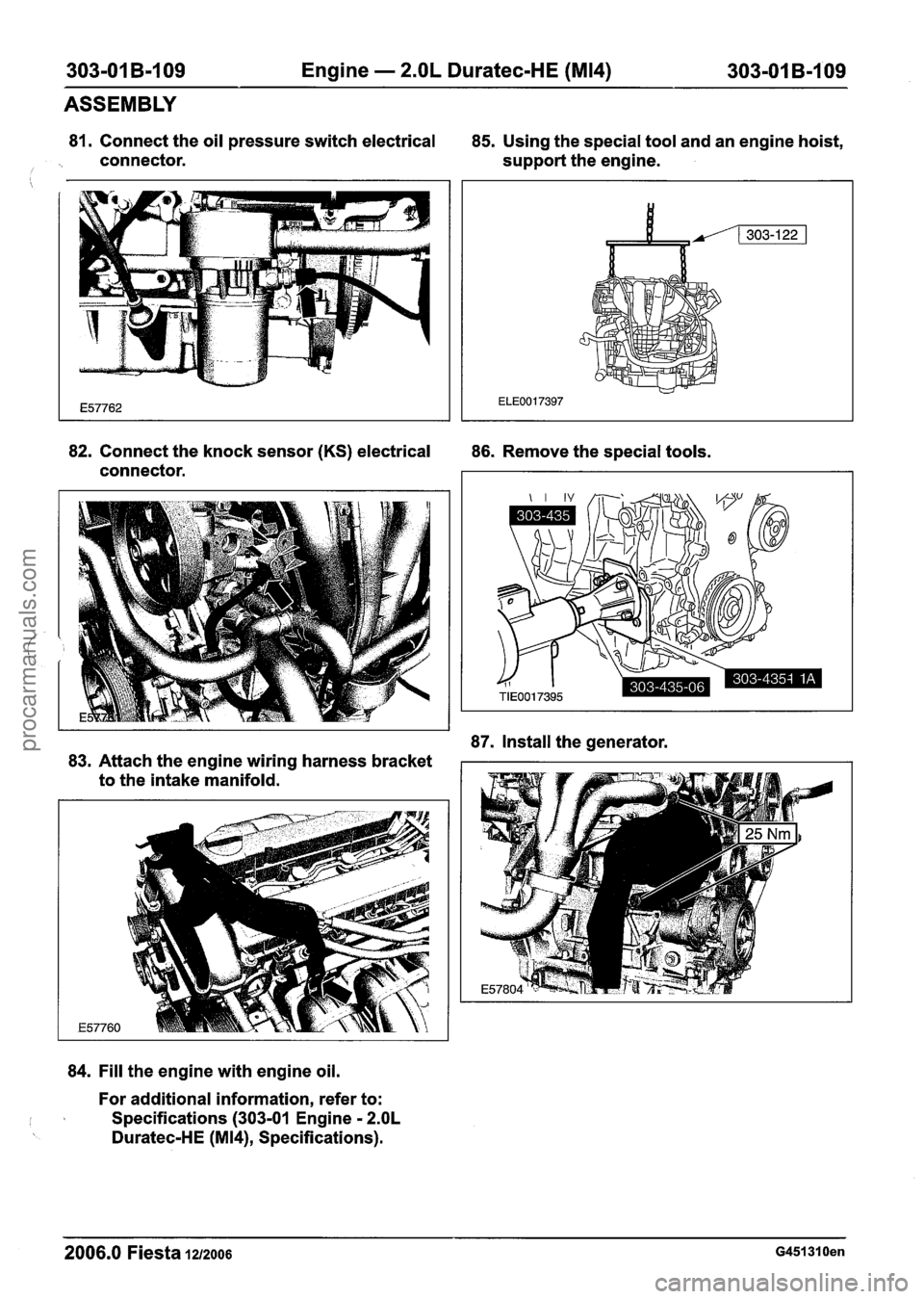
81. Connect the oil pressure switch electrical
85. Using the special tool and an engine hoist,
connector. support the engine.
i
ASSEMBLY
82. Connect the knock sensor (KS) electrical
86. Remove the special tools.
connector.
87. Install the generator.
83. Attach the engine wiring harness bracket
to the intake manifold.
84. Fill the engine with engine oil.
For additional information, refer to:
I I Specifications (303-01 Engine - 2.OL
Duratec-HE (M14), Specifications).
2006.0 Fiesta 1z/zoo6 G451310en
procarmanuals.com
Page 732 of 1226
303-01 B-I 10 Engine - 2.OL Duratec-HE (M14) 303101 B-110
ASSEMBLY
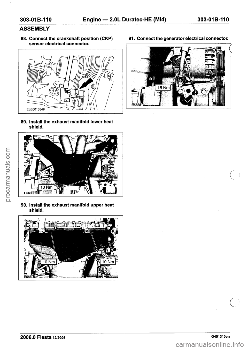
88. Connect the crankshaft position (CKP) 91. Connect
the generator electrical connector.
sensor electrical connector.
89. Install the exhaust manifold lower heat
shield.
90. Install the exhaust manifold upper heat
shield.
2006.0 Fiesta 1212006 G451310en
procarmanuals.com
Page 740 of 1226

303-01 B-I 18 Engine - 2.OL Duratec-HE (M14) 303-01 B-118
INSTALLATION
44. Attach the power steering high-pressure 47.
Connect the catalyst monitor sensor
line retaining bracket to the transaxle. electrical
connector.
//
45. Install the engine wiring harness bracket. 48.
Connect the power steering pump switch
electrical connector.
46. Connect the engine wiring harness
electrical connector.
49. Install the battery tray support bracket.
2006.0 Fiesta 1212006 G451291 en
procarmanuals.com
Page 749 of 1226
Enaine Cooling - 1.3L Duratec-8V
(~ocah)ll.25L ~Cratec-1 6~ (Sigma)ll.4L
303-03A-7 Duratec-1 6V (Sigma)ll .6L Duratec-1 6V (Sigma) 303-03A-7
DESCRIPTION AND OPERATION
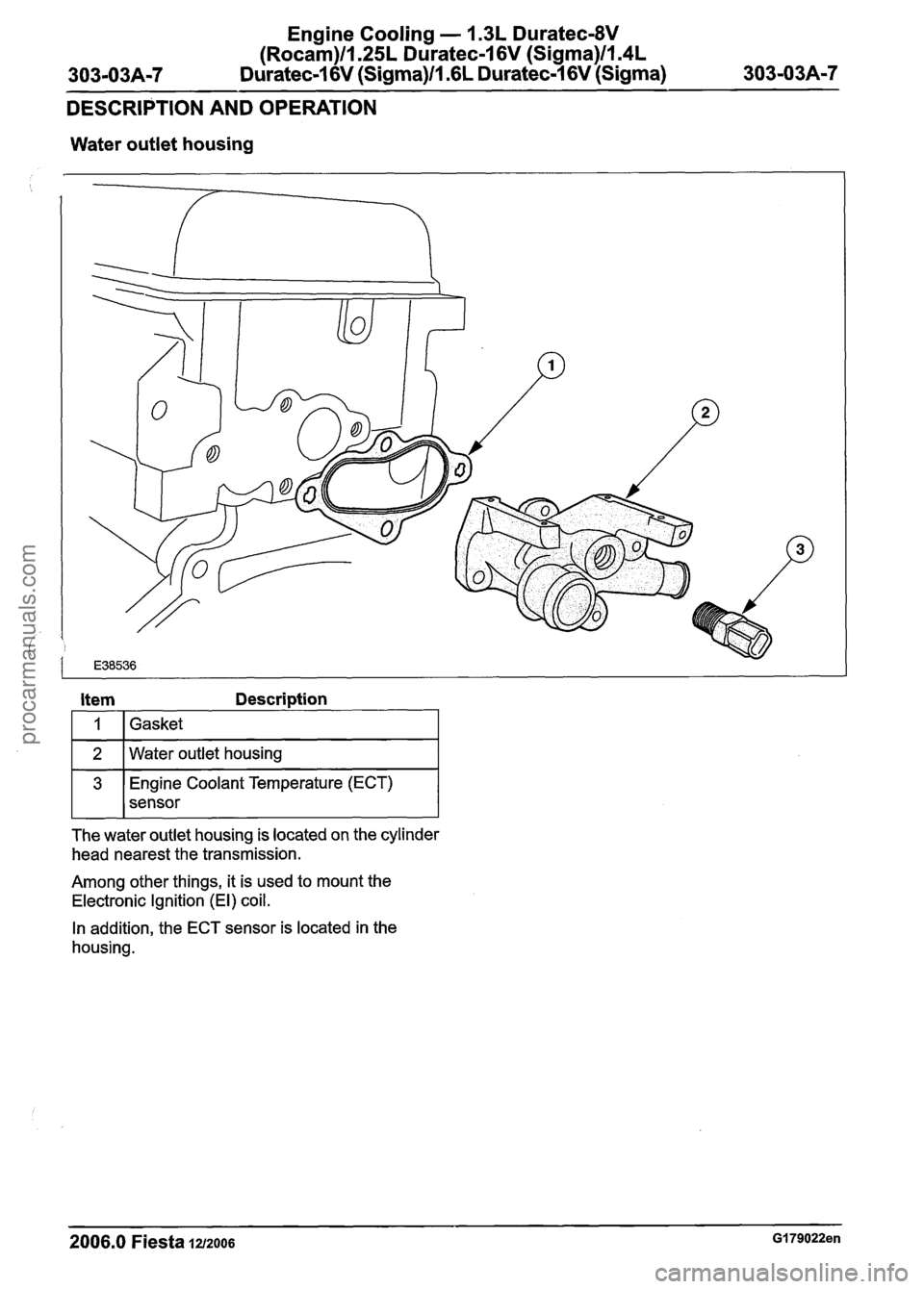
Water outlet housing
Coolant Temperature (ECT)
sensor
Item Description
The water outlet housing is located on the cylinder
head nearest the transmission.
1
2
Among other things, it is used to mount the
Electronic Ignition (El) coil.
Gasket
Water outlet housing
In addition, the ECT sensor is located in the
housing.
2006.0 Fiesta 1212006 GI 79022en
procarmanuals.com
Page 750 of 1226
Engine Cooling - 1.3L Duratec-8V
(Rocam)ll.25L Duratec-1 6V (Sigma)ll.4L
303-03A-8 Duratec-1 6V (Sigma)/l .6L Duratec-1 6V (Sigma) 303-03A-8
DIAGNOSIS AND TESTING
Engine Cooling
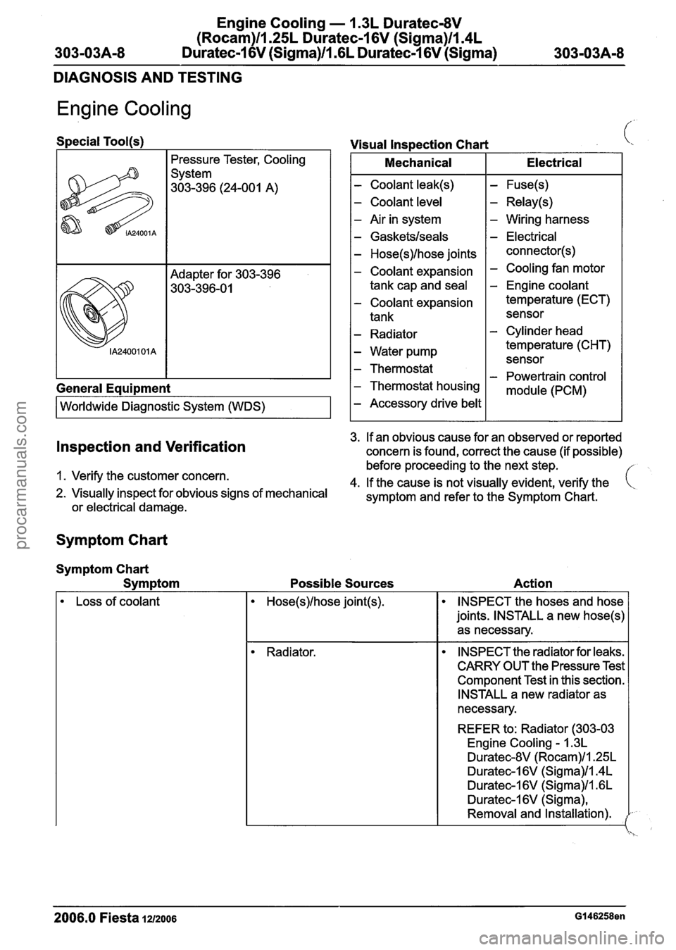
Special Tool(~)
Pressure Tester,
Cooling
System
303-396 (24-001 A)
General
Equipment
I Worldwide Diagnostic System (WDS) I
Visual Inspection Chart i,
I Mechanical I Electrical I
- Coolant leak(s)
- Coolant level
- Air in system
- Gasketslseals
- Hose(s)lhose joints
- Coolant expansion
tank cap and
seal
- Coolant expansion
tank
- Radiator
- Water pump
- Thermostat
- Thermostat housing
- Accessory drive belt
- Fuse(s)
- Relay(s)
- Wiring harness
- Electrical
connector(s)
- Cooling fan motor
- Engine coolant
temperature (ECT)
sensor
- Cylinder head
temperature (CHT) sensor
- Powertrain control
module (PCM)
3.
If an obvious cause for an observed or reported Inspection and Verification concern is found, correct the cause (if possible)
before proceeding to the next step.
1. Verify the customer concern.
4.
If the cause is not visually evident, verify the ( 2. Visually inspect for obvious signs of mechanical
symptom and refer to the Symptom Chart.
or
electrical damage.
Symptom Chart
Symptom Chart
Svm
ptom Possible Sources Action
Loss of
coolant INSPECT the hoses and hose
joints. INSTALL a new
hose(s)
as necessary.
Radiator. INSPECT the radiator for leaks.
CARRY OUT the Pressure Test
Component Test in this section.
INSTALL a new radiator as
necessary.
REFER to: Radiator (303-03 Engine
Cooling - 1.3L
Duratec-8V (Rocam)/l.25L
Duratec-1 6V (Sigma)1ln4L
Duratec-1 6V (Sigma)ll .6L
Duratec-I 6V (Sigma),
Removal and Installation).
2006.0 Fiesta 1212006 GI 46258en
procarmanuals.com
Page 757 of 1226
Engine Cooling - 1.3L Duratec-8V
(Rocam)llI25L Duratec-1 6V (Sigma)llI4L
303-03A-I 5 Duratec-1 6V (Sigma)/l .6L Duratec-1 6V (Sigma) 303-0344-15
DIAGNOSIS AND TESTING
Symptom Possible Sources Action
Cooling fan motor. CHECK the operation of the
cooling fan motor. REFER to
WDS.
Engine. INSPECT
the engine, cylinder
head, cylinder block and
cylinder head gasket.
REFER to: Cylinder Head (303-
01 Engine - 1.25L Duratec-
16V (Sigma)/l.4L Duratec-
16V (Sigma)/l.GL Duratec-
16V (Sigma), In-vehicle
Repair).
, The engine does not reach
normal operating temperature. ECT sensor. CHECK the ECT sensor.
I REFER to WDS.
Temperature gauge. CHECK
the instrument cluster
engine temperature gauge.
REFER to: lnstrument Cluster
- Vehicles Built Up To:
1012005 (41 3-01 lnstrument
Cluster, Diagnosis and
Testing)
I lnstrument Cluster - Vehicles
Built From:
1012005 (41 3-01
lnstrument Cluster, Diagnosis
and Testing).
Thermostat. CARRY OUT the Thermostat
Test Component Test in this
section. INSTALL a new ther-
mostat as necessary.
REFER to: Thermostat
- I .3L
Duratec-8V
(Rocam) (303-03
Engine Cooling
- 1.3L
Duratec-8V (Rocam)ll.25L
Duratec-16V (Sigma)/l.4L
Duratec-1 6V (Sigma)ll .6L
Duratec-16V (Sigma),
Removal and Installation)
I Thermostat - 1.25L Duratec-
16V (Sigma)/l.4L Duratec-
16V (Sigma)ll .6L Duratec-
16V (Sigma) (303-03 Engine
Cooling
- 1.3L Duratec-8V
(Rocam)ll.25L Duratec-1 6V
(Sigma)ll.4L Duratec-1 6V
(Sigma)/l .6L Duratec-I 6V
(Sigma), Removal and
Installation).
2006.0 Fiesta 1212oo6 GI 46258en
procarmanuals.com
Page 758 of 1226
Engine Cooling - 1.3L Duratec-8V
(Rocam)ll.25L Duratec-I 6V (Sigma)ll.4L
303-03A-16 Duratec-1 6V (Sigma)/l .6L Duratec-1 6V (Sigma) 303-03A-16
DIAGNOSIS AND TESTING
Component Tests
Pressure Test
A WARNING:When releasing the system
pressure, cover the expansion tank cap
with a thick cloth to prevent the possibility
of coolant scalding, Failure to follow this
instruction may result in personal injury.
1. Remove the coolant expansion tank cap.
2.
Install the special tools to the coolant expansion
tank.
3. Pressurize the system to the
coolant expansion
tank cap
release pressure.
REFER to: Specifications (303-03 Engine
Cooling - 1.3L Duratec-8V (Rocam)/l.25L
Duratec-I 6V (Sigma)/l.4L Duratec-1 6V
(Sigma)/l .6L Duratec-1 6V (Sigma),
Specifications).
4. Observe the
cooling system pressure tester
gauge reading for
approximately two minutes.
The pressure
should not drop during this time.
If the system holds pressure, proceed to step
6.
If the system does not hold pressure, check
it
thoroughly for coolant leaks.
5. Check the engine for coolant leaks. Drain the
cooling system, repair any coolant leaks found
and
fill and bleed the cooling system as
necessary.
REFER to:
Cooling System Draining, Filling and
Bleeding - 1.3L Duratec-8V (Rocam)/l.25L
Duratec-I 6V (Sigma)/l.4L Duratec-1 6V
(Sigma)/l .6L Duratec-1 6V (Sigma) (303-03
Engine
Cooling - 1.3L Duratec-8V
(Rocam)/l.25L Duratec-1 6V (Sigma)/l.4L
Duratec-1 6V (Sigma)/l .6L Duratec-1 6V
(Sigma), General Procedures).
Clean the radiator thoroughly before leak testing
it, to prevent contamination of the water in the test
tank. Leak test the radiator in
clean water with 138(
kpa (20 psi) air pressure. Check it thoroughly for
air
leaks. INSTALL a new radiator if necessary.
REFER to: Radiator (303-03 Engine
Cooling - 1.3L
Duratec-8V (Rocam)/l.25L Duratec-I 6V
(Sigma)/l.4L Duratec-I 6V (Sigma)ll .6L
Duratec-I 6V (Sigma), Removal and Installation).
Coolant Expansion Tank Cap Pressure Test
A WARNING:When releasing the system
pressure, cover the expansion tank cap
with a thick cloth to prevent the possibility
of coolant scalding, Failure to follow this
instruction may result in personal injury.
1. Remove the coolant expansion tank cap.
2. Use water to clean the area of the rubber seal
and pressure relief valve. Install the pressure
tester and adapter and immerse the
coolant
expansion tank cap in water .
N0TE:lf the plunger of the pump is depressed too
quickly, an erroneous pressure reading will result. l-
3. Slowly depress the plunger of the pressure test
pump until the pressure gauge reading stops
increasing, and note the highest pressure
reading obtained.
4.
Release pressure by turning the pressure relief
screw counterclockwise. Tighten the pressure
relief screw and repeat step 3 at least twice to
make sure the pressure test reading is
repeatable and within acceptable gauge reading
limits of the coolant expansion tank cap.
5.
If the pressure test gauge readings are not
within the
acceptable gauge reading limits,
INSTALL a new coolant expansion tank cap.
6. Recheck the system by repeating steps 3 and
4 at least twice.
Thermostat Test
Radiator Leak Test, Removed From Vehicle
A CAUTI0N:Radiator internal pressure must
not exceed
130 kpa (20 psi) or damage may
result.
1. Connect the WDS to the data link connector
(DLC).
2. Using the WDS
datalogger function, SELECT
the
following sensors (as applicable to the
application):
IAT - intake air temperature (IAT) sensor
ECT
- engine coolant temperature (ECT) sensort
CHT - cylinder head temperature (CHT) sensori
LOAD - engine load
VSS - vehicle speed sensor (VSS)
2006.0 Fiesta 1212006 GI 46258en
procarmanuals.com