lock FORD FIESTA 2007 Workshop Manual
[x] Cancel search | Manufacturer: FORD, Model Year: 2007, Model line: FIESTA, Model: FORD FIESTA 2007Pages: 1226, PDF Size: 61.26 MB
Page 715 of 1226
303-01 B-93 Engine - 2.OL Duratec-HE (M14) 303-01 B-93
DISASSEMBLY
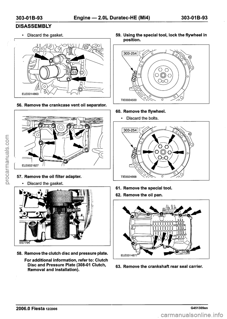
Discard the gasket. 59. Using
the special tool, lock the flywheel in
position.
56. Remove the crankcase vent oil separator.
60. Remove the flywheel.
Discard the bolts.
57.
Remove the oil filter adapter.
Discard the gasket.
61.
Remove the special tool.
62. Remove the oil pan.
58. Remove the clutch disc and pressure plate.
For additional information, refer to: Clutch
Disc and Pressure 'late (308-01 Clutch, 63. Remove the crankshaft rear seal carrier.
Removal and Installation).
2006.0 Fiesta 1212006 G451309en
procarmanuals.com
Page 718 of 1226
303-01 B-96 Engine - 2.OL Duratec-HE (M14) 303-01 B-96
ASSEMBLY
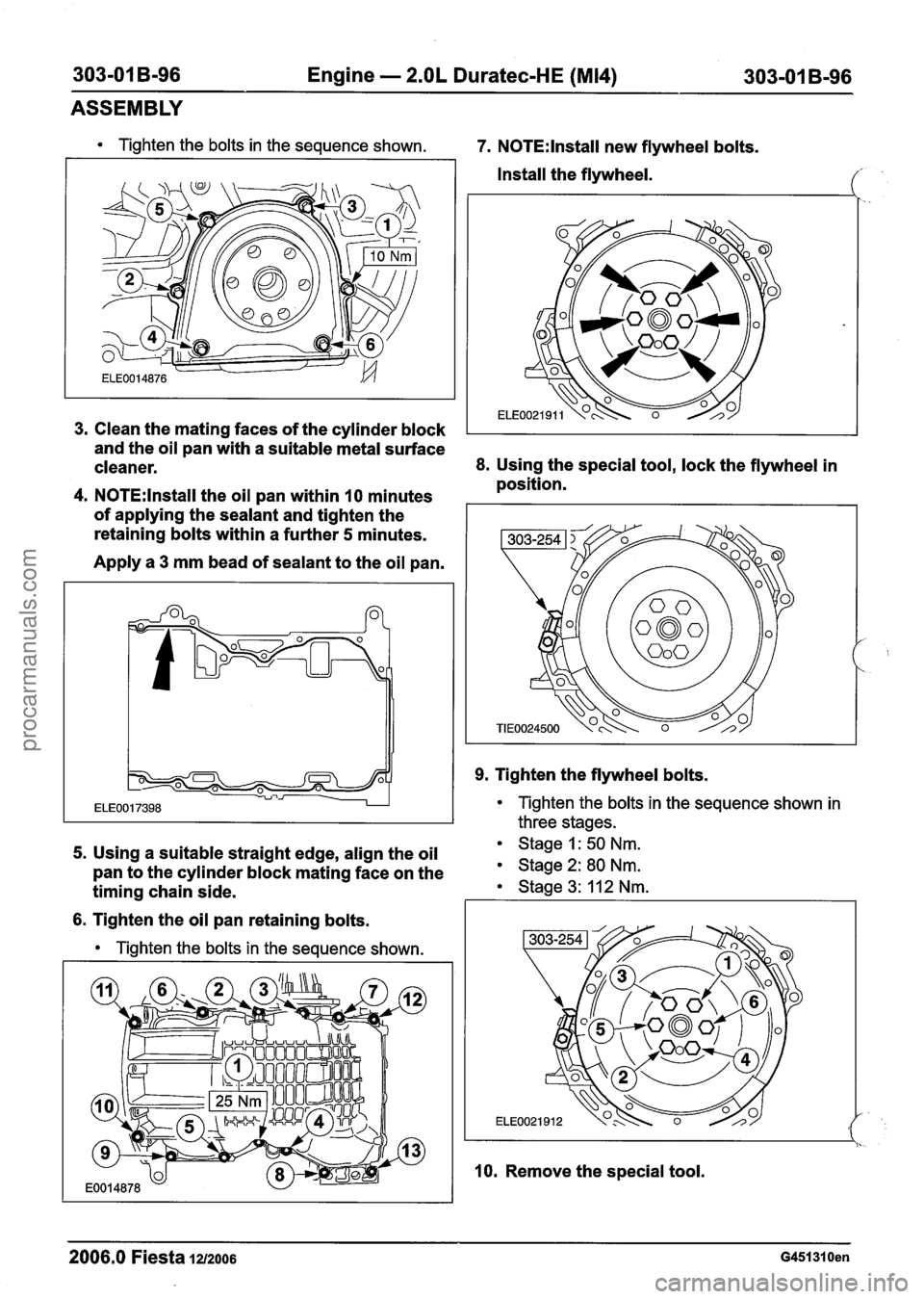
Tighten the bolts in the sequence shown. 7. N0TE:lnstall new flywheel bolts.
Install the flywheel.
Clean the mating faces of the cylinder block
I
and the oil pan with a suitable metal surface
cleaner.
8. Using the special tool, lock the flywheel in
position.
N0TE:lnstall the oil pan within 10 minutes
of applying the sealant and tighten the
retaining bolts within a further
5 minutes.
Apply a
3 mm bead of sealant to the oil pan.
9. Tighten the flywheel bolts.
Tighten the bolts in the sequence shown in
three stages.
5. Using a suitable straight edge, align the oil Stage 1: 50 Nm.
pan to the cylinder block mating face on the Stage 2: 80 Nm.
timing chain side. Stage 3: 11 2 Nm. I I
6. Tighten the oil pan retaining bolts.
Tighten the bolts in the sequence shown.
l I. -.
10. Remove the special tool.
2006.0 Fiesta 1212006 G451310en
procarmanuals.com
Page 719 of 1226
303-01 B-97 Engine - 2.OL Duratec-HE (M14) 303-01 B-97
ASSEMBLY
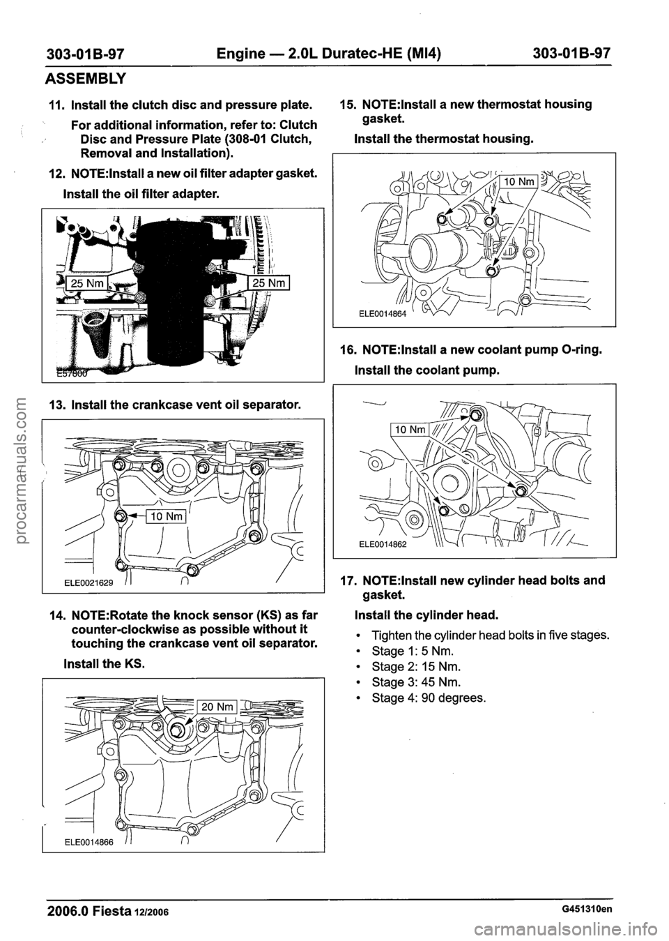
11. lnstall the clutch disc and pressure plate. 15. N0TE:lnstall a
new thermostat housing
'. For additional information, refer to: Clutch gasket.
Disc and Pressure Plate (308-01 Clutch, Install
the thermostat housing.
Removal and Installation).
12.
N0TE:lnstall a new oil filter adapter gasket.
lnstall the oil filter adapter.
13. lnstall the crankcase vent oil separator. 16.
N0TE:lnstall a
new coolant pump O-ring.
lnstall the coolant pump.
17.
N0TE:lnstall new cylinder head bolts and
gasket.
14.
N0TE:Rotate the knock sensor (KS) as far Install
the cylinder head.
counter-clockwise as possible without
it Tighten the cylinder head bolts in five stages. touching the crankcase vent oil separator. Stage I: 5 Nm.
lnstall the KS. stage 2: 15 Nm.
Stage 3: 45 Nm.
Stage 4: 90 degrees.
2006.0 Fiesta 1212006 G451310en
procarmanuals.com
Page 723 of 1226
303-01 B-I 01 Engine - 2.OL Duratec-HE (M14) 303-01 B-101
ASSEMBLY
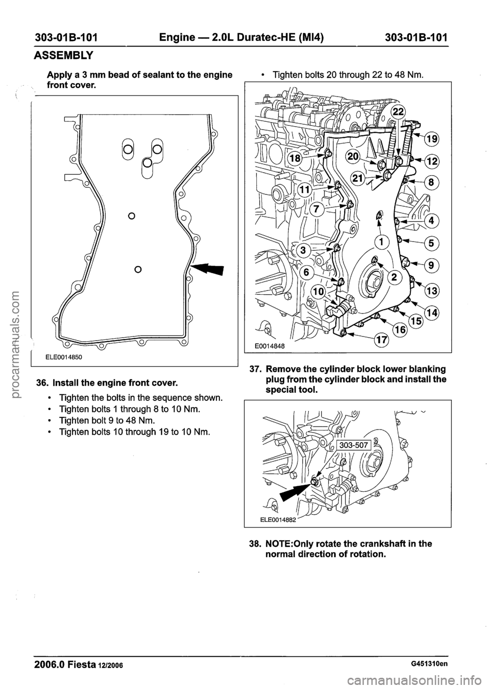
Apply a 3 mm bead of sealant to the engine Tighten bolts 20 through 22 to 48 Nm.
. front cover.
i
37. Remove the cylinder block lower blanking
36. Install the engine front cover. plug from
the cylinder block and install the
special tool.
Tighten the bolts in the sequence shown.
Tighten bolts 1 through 8 to 10 Nm.
Tighten bolt 9 to 48 Nm.
Tighten bolts 10 through 19 to 10 Nm.
38. N0TE:Only rotate the crankshaft in the
normal direction of rotation.
2006.0 Fiesta IZIZOO~ G451310en
procarmanuals.com
Page 726 of 1226
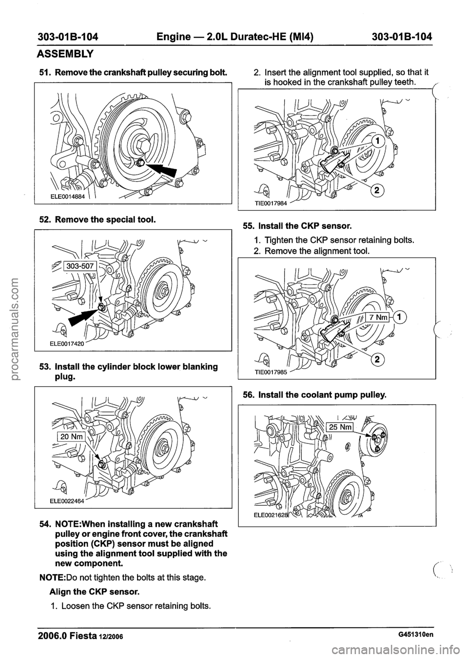
303-01 B-I 04 Engine - 2.OL Duratec-HE (M14) 303-01 B-I 04
ASSEMBLY
51. Remove the crankshaft pulley securing bolt. 2. Insert the alignment tool supplied, so that it
is hooked in the crankshaft pulley teeth.
I
52. Remove the special tool.
53. Install the cylinder block lower blanking
plug9
54. N0TE:When installing a new crankshaft
pulley or engine front cover, the crankshaft
position
(CKP) sensor must be aligned
using the alignment tool supplied with the
new component.
N0TE:Do not tighten the bolts at this stage.
Align the CKP sensor.
1.
Loosen the CKP sensor retaining bolts.
55. Install the CKP sensor.
I. Tighten the CKP sensor retaining bolts.
2. Remove the alignment tool.
56. Install the coolant pump pulley.
2006.0 Fiesta 1212006 G451310en
procarmanuals.com
Page 733 of 1226

303-01 B-I11 Engine - 2.OL Duratec-HE (M14) 303-01 B-111
INSTALLATION
Engine
i Special Tool(s)
I
I Remover/lnstaller, Hose
General Equipment
I Workshop table 1
I Securing straps I
I Engine hoist I --
A WARNING:Do not smoke or carry lighted
tobacco or open flame of any type when
working on or near any fuel related
components. Highly flammable vapors are
always present and may ignite. Failure to
follow these instructions may result in
personal injury.
1. N0TE:Using suitable retaining straps, secure
the engine on the workshop table.
Support the engine with wooden blocks.
2. Install the transaxle.
3. Install the transaxle upper retaining bolts.
4. Install the transaxle left-hand retaining bolts.
5. Install the transaxle right-hand retaining
bolts.
2006.0 Fiesta 1212006 ~451291 en
procarmanuals.com
Page 735 of 1226
303-01 B-I 13 Engine - 2.OL Duratec-HE (M14) 303-01 B-113
INSTALLATION
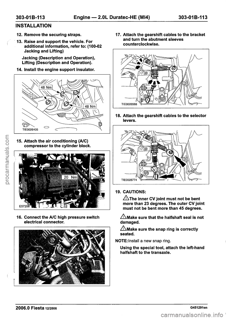
12. Remove the securing straps. 17.
Attach the gearshift cables to the bracket
13. Raise and support the vehicle. For and
turn the abutment sleeves
( additional information, refer to: (I 00-02 counterclockwise.
Jacking and Lifting)
Jacking (Description and Operation),
Lifting (Description and Operation).
14. Install the engine support insulator.
15. Attach the air conditioning (NC)
compressor to the cylinder block. 18.
Attach the gearshift cables to the selector
levers.
19. CAUTIONS:
A~he inner CV joint must not be bent
more than 23 degrees. The outer CV joint
must not be bent more than 45 degrees.
16. Connect the
NC high pressure switch n~ake sure that the halfshaft seal is not
electrical connector. damaged.
n~ake sure the snap ring is correctly
seated.
N0TE:lnstall a new snap ring.
Using the special tool, attach the left-hand
halfshaft to the transaxle.
2006.0 Fiesta 1212006 ~451291 en
procarmanuals.com
Page 747 of 1226

Engine Cooling - I .3L DuratecdV
(Rocam)ll.25L Duratec-1 6V (Sigma)ll.4L
Duratec-1 6V (Sigma)ll .6L Duratec-1 6V (Sigma)
DESCRIPTION AND OPERATION
Components
Coolant pump
The coolant pump is secured to the engine block
at the timing gear end.
Item Description It is driven through a pulley b; the accessory drive
2006.0 Fiesta 1212006 GI 79022en
belt.
The gasket for the coolant pump must not be
reused. 1
2
I
Coolant pump
Coolant pump gasket
procarmanuals.com
Page 748 of 1226
Engine Cooling - I .3L Duratec-8V
(Rocam)ll.25L Duratec-1 6V (Sigma)ll.4L
303-03A-6 Duratec-I 6V (Sigma)/l .6L Duratec-I 6V (Sigma) 303-03A-6
DESCRIPTION AND OPERATION
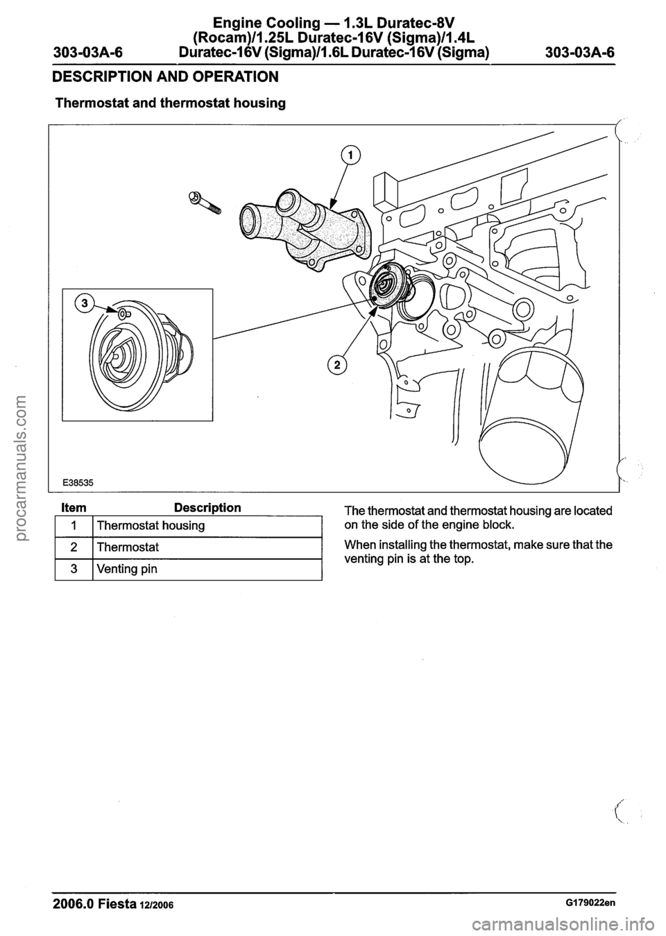
Thermostat and thermostat housing
Item Description The thermostat and thermostat housing are located
- - -- - -- - -- --
2006.0 Fiesta 1212006 GI 79022en
I 1 I Thermostat housing
2
3
on the side of the engine block.
Thermostat
Venting pin When
installing the thermostat, make sure that the
venting pin is at the top.
procarmanuals.com
Page 752 of 1226
Engine Cooling - 1.3L Duratec-8V
(Rocam)llI25L Duratec-1 6V (Sigma)ll.4L
Duratec-1 6V (Sigma)/l .6L Duratec-1 6V (Sigma)
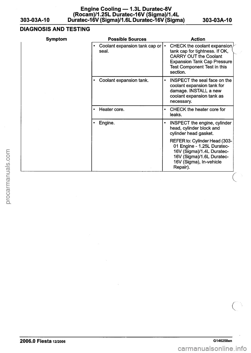
DIAGNOSIS AND TESTING
Symptom
Possible Sources Action
Coolant expansion tank cap or
seal.
Coolant expansion tank.
Heater core.
Engine. CHECK
the
coolant expansion
tank cap for tightness. If OK,
I
CARRY OUT the Coolant
Expansion Tank Cap Pressure
Test Component Test in this
section.
INSPECT the seal face on the
coolant expansion tank for
damage. INSTALL a new
coolant expansion tank as
necessary.
CHECK the heater core for
leaks.
INSPECT the engine, cylinder
head, cylinder block and
cylinder head gasket.
REFER to:
Cylinder Head (303-
01 Engine
- I .25L Duratec-
16V
(Sigma)/l.4L Duratec-
16V
(Sigma)/l .6L Duratec-
16V (Sigma),
In-vehicle
Repair).
2006.0 Fiesta 1212006 GI 46258en
procarmanuals.com