service indicator FORD MUSTANG 1969 Volume One Chassis
[x] Cancel search | Manufacturer: FORD, Model Year: 1969, Model line: MUSTANG, Model: FORD MUSTANG 1969Pages: 413, PDF Size: 75.81 MB
Page 195 of 413
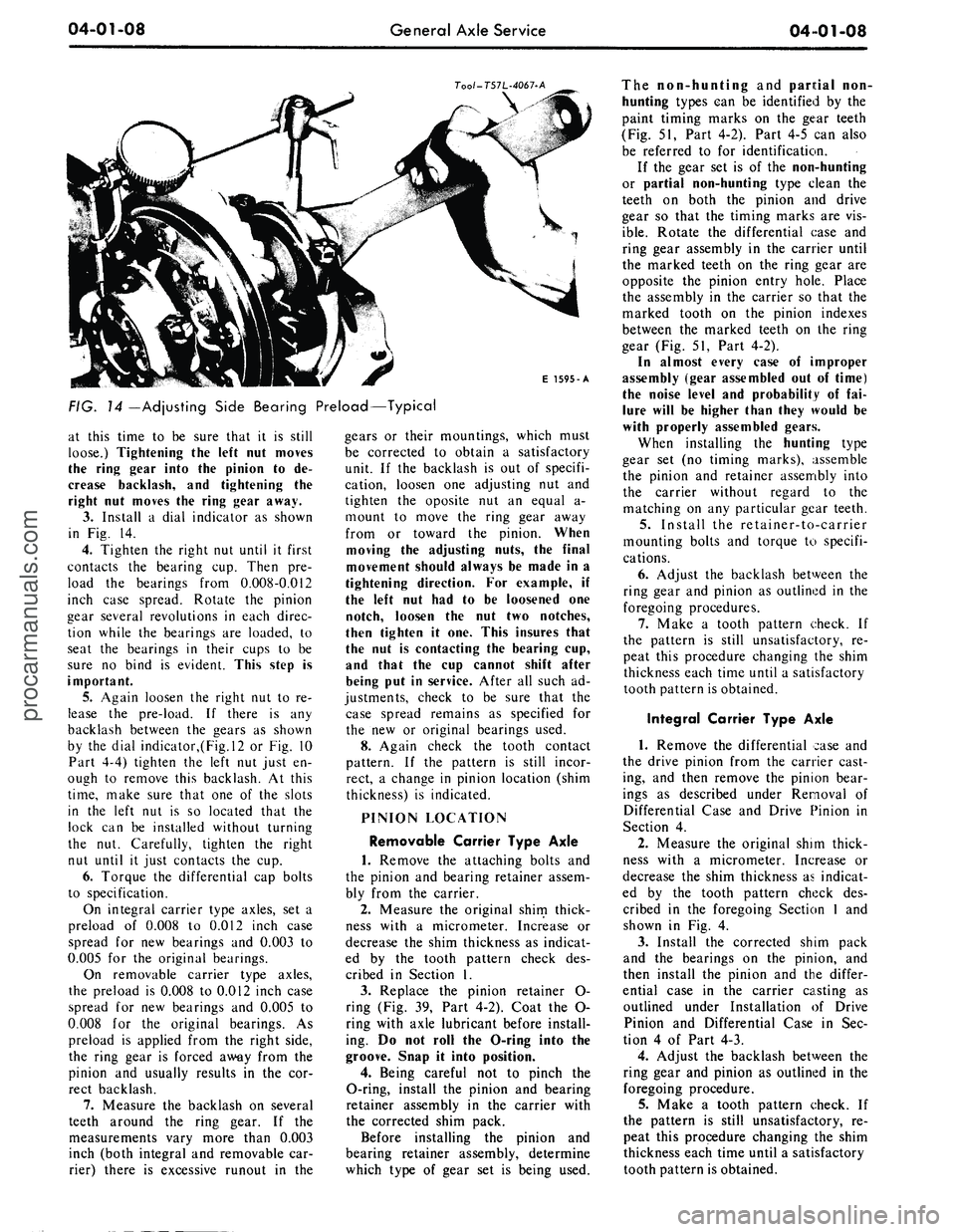
04-01-08
General Axle Service
04 01-08
Too/-T57L-4067-A
E 1595-A
FIG.
14
—Adjusting Side Bearing Preload—Typical
at this time to be sure that it is still
loose.) Tightening the left nut moves
the ring gear into the pinion to de-
crease backlash, and tightening the
right nut moves the ring gear away.
3.
Install a dial indicator as shown
in Fig. 14.
4.
Tighten the right nut until it first
contacts the bearing cup. Then pre-
load the bearings from 0.008-0.012
inch case spread. Rotate the pinion
gear several revolutions in each direc-
tion while the bearings are loaded, to
seat the bearings in their cups to be
sure no bind is evident. This step is
important.
5. Again loosen the right nut to re-
lease the pre-load. If there is any
backlash between the gears as shown
by the dial indicator,(Fig.l2 or Fig. 10
Part 4-4) tighten the left nut just en-
ough to remove this backlash. At this
time,
make sure that one of the slots
in the left nut is so located that the
lock can be installed without turning
the nut. Carefully, tighten the right
nut until it just contacts the cup.
6. Torque the differential cap bolts
to specification.
On integral carrier type axles, set a
preload of 0.008 to 0.012 inch case
spread for new bearings and 0.003 to
0.005 for the original bearings.
On removable carrier type axles,
the preload is 0.008 to 0.012 inch case
spread for new bearings and 0.005 to
0.008 for the original bearings. As
preload is applied from the right side,
the ring gear is forced away from the
pinion and usually results in the cor-
rect backlash.
7.
Measure the backlash on several
teeth around the ring gear. If the
measurements vary more than 0.003
inch (both integral and removable car-
rier) there is excessive runout in the
gears or their mountings, which must
be corrected to obtain a satisfactory
unit. If the backlash is out of specifi-
cation, loosen one adjusting nut and
tighten the oposite nut an equal a-
mount to move the ring gear away
from or toward the pinion. When
moving the adjusting nuts, the final
movement should always be made in a
tightening direction. For example, if
the left nut had to be loosened one
notch, loosen the nut two notches,
then tighten it one. This insures that
the nut is contacting the bearing cup,
and that the cup cannot shift after
being put in service. After all such ad-
justments, check to be sure that the
case spread remains as specified for
the new or original bearings used.
8. Again check the tooth contact
pattern. If the pattern is still incor-
rect, a change in pinion location (shim
thickness) is indicated.
PINION LOCATION
Removable Carrier Type Axle
1.
Remove the attaching bolts and
the pinion and bearing retainer assem-
bly from the carrier.
2.
Measure the original shim thick-
ness with a micrometer. Increase or
decrease the shim thickness as indicat-
ed by the tooth pattern check des-
cribed in Section 1.
3.
Replace the pinion retainer O-
ring (Fig. 39, Part 4-2). Coat the O-
ring with axle lubricant before install-
ing. Do not roll the O-ring into the
groove. Snap it into position.
4.
Being careful not to pinch the
O-ring, install the pinion and bearing
retainer assembly in the carrier with
the corrected shim pack.
Before installing the pinion and
bearing retainer assembly, determine
which type of gear set is being used.
The non-hunting and pantial non-
hunting types can be identified by the
paint timing marks on the gear teeth
(Fig. 51, Part 4-2). Part 4-5 can also
be referred to for identification.
If the gear set is of the non-hunting
or partial non-hunting type clean the
teeth on both the pinion and drive
gear so that the timing marks are vis-
ible.
Rotate the differential case and
ring gear assembly in the carrier until
the marked teeth on the ring gear are
opposite the pinion entry hole. Place
the assembly in the carrier so that the
marked tooth on the pinion indexes
between the marked teeth on the ring
gear (Fig. 51, Part 4-2).
In almost every case of improper
assembly (gear assembled out of time)
the noise level and probability of fai-
lure will be higher than they would be
with properly assembled gears.
When installing the hunting type
gear set (no timing marks), assemble
the pinion and retainer assembly into
the carrier without regard to the
matching on any particular gear teeth.
5.
Install the retainer-to-carrier
mounting bolts and torque to specifi-
cations.
6. Adjust the backlash between the
ring gear and pinion as outlined in the
foregoing procedures.
7.
Make a tooth pattern check. If
the pattern is still unsatisfactory, re-
peat this procedure changing the shim
thickness each time until a satisfactory
tooth pattern is obtained.
Integral Carrier Type Axle
1.
Remove the differential case and
the drive pinion from the carrier cast-
ing, and then remove the pinion bear-
ings as described under Removal of
Differential Case and Drive Pinion in
Section 4.
2.
Measure the original shim thick-
ness with a micrometer. Increase or
decrease the shim thickness as indicat-
ed by the tooth pattern check des-
cribed in the foregoing Section 1 and
shown in Fig. 4.
3.
Install the corrected shim pack
and the bearings on the pinion, and
then install the pinion and the differ-
ential case in the carrier casting as
outlined under Installation of Drive
Pinion and Differential Case in Sec-
tion 4 of Part 4-3.
4.
Adjust the backlash between the
ring gear and pinion as outlined in the
foregoing procedure.
5.
Make a tooth pattern check. If
the pattern is still unsatisfactory, re-
peat this procedure changing the shim
thickness each time until a satisfactory
tooth pattern is obtained.procarmanuals.com
Page 196 of 413
04-01-09
General Axle Service
04-01-09
CLEANING AND INSPECTION
INSPECTION BEFORE
DISASSEMBLY OF CARRIER
(ALL AXLES)
The differential case or carrier
should be inspected before any parts
are removed from it. These inspec-
tions can help to find the cause of the
trouble and to determine the correc-
tions needed.
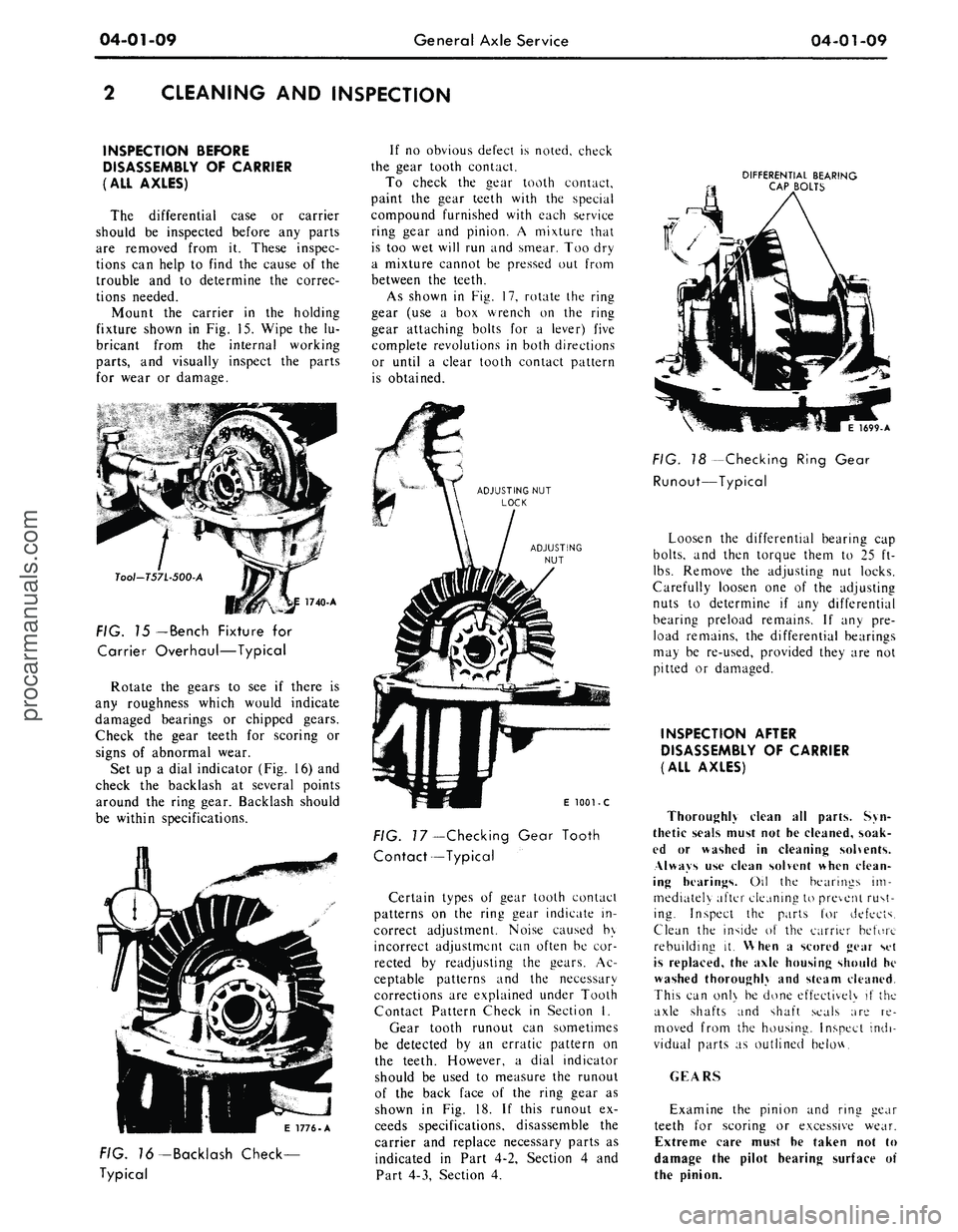
Mount the carrier in the holding
fixture shown in Fig. 15. Wipe the lu-
bricant from the internal working
parts,
and visually inspect the parts
for wear or damage.
Tool-T57L-500-A
FIG. 15
— Bench
Fixture for
Carrier Overhaul—Typical
Rotate the gears to see if there is
any roughness which would indicate
damaged bearings or chipped gears.
Check the gear teeth for scoring or
signs of abnormal wear.
Set up a dial indicator (Fig. 16) and
check the backlash at several points
around the ring gear. Backlash should
be within specifications.
If no obvious defect is noted, check
the gear tooth contact.
To check the gear tooth contact,
paint the gear teeth with the special
compound furnished with each service
ring gear and pinion. A mixture that
is too wet will run and smear. Too dry
a mixture cannot be pressed out from
between the teeth.
As shown in Fig. 17, rotate the ring
gear (use a box wrench on the ring
gear attaching bolts for a lever) five
complete revolutions in both directions
or until a clear tooth contact pattern
is obtained.
DIFFERENTIAL BEARING
CAP BOLTS
E 1776-A
FIG. 76-Backlash Check-
Typical
E
1001 - C
FIG.
7
7—Checking Gear Tooth
Contact—Typical
Certain types of gear tooth contact
patterns on the ring gear indicate in-
correct adjustment. Noise caused by
incorrect adjustment can often be cor-
rected by readjusting the gears. Ac-
ceptable patterns and the necessary
corrections are explained under Tooth
Contact Pattern Check in Section I.
Gear tooth runout can sometimes
be detected by an erratic pattern on
the teeth. However, a dial indicator
should be used to measure the runout
of the back face of the ring gear as
shown in Fig. 18. If this runout ex-
ceeds specifications, disassemble the
carrier and replace necessary parts as
indicated in Part 4-2, Section 4 and
Part 4-3, Section 4.
1699-A
FIG. 18 -Checking Ring Gear
Runout—Typical
Loosen the differential bearing cap
bolts,
and then torque them to 25 ft-
lbs.
Remove the adjusting nut locks.
Carefully loosen one of the adjusting
nuts to determine if any differential
bearing preload remains. If any pre-
load remains, the differential bearings
may be re-used, provided they are not
pitted or damaged.
INSPECTION AFTER
DISASSEMBLY OF CARRIER
(ALL AXLES)
Thoroughly clean all parts. Syn-
thetic seals must not he cleaned, soak-
ed or washed in cleaning solvents.
Always use clean solvent when clean-
ing hearings. Oil the bearings im-
mediately after cleaning to prevent rust-
ing. Inspect the parts for defects.
Clean the inside of the carrier before
rebuilding it. When a scored gear set
is replaced, the axle housing should he
washed thoroughly and steam cleaned.
This can onl\ be done effectively if the
axle shafts and shaft seals are re-
moved from the housing. Inspect indi-
vidual parts as outlined below.
GEARS
Examine the pinion and ring gear
teeth for scoring or excessive wear.
Extreme care must he taken not to
damage the pilot hearing surface of
the pinion.procarmanuals.com
Page 215 of 413
04-02-18
Rear Axle — Removable Carrier Type
04-02-18
E 1195-C
FIG. 41—Removing
or
Installing
Pinion
and
Retainer Assembly
10.
Hold
the
flange with
the
tool
shown
in Fig. 22
(Ford)
or Fig. 23
(Mercury),
and
torque
the
pinion shaft
nut
to 175
ft-lbs.
Do not
exceed
175
ft-Ibs
at
this time.
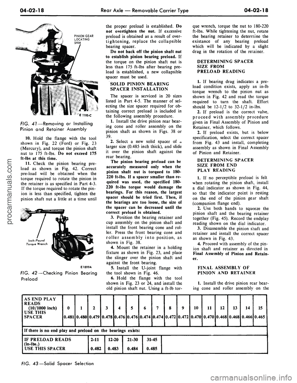
11.
Check
the
pinion bearing
pre-
load
as
shown
in Fig. 42.
Correct
pre-load will
be
obtained when
the
torque required
to
rotate
the
pinion
in
the retainer
is as
specified
in
Part
4-3.
If
the
torque required
to
rotate
the pin-
ion
is
less than specified, tighten
the
pinion shaft
nut a
little
at a
time until
Inch-Pound
Torque Wrench
E1899A
FIG. 42—Checking Pinion Bearing
Preload
the proper preload
is
established.
Do
not overtighten
the nut. If
excessive
preload
is
obtained
as a
result
of
over-
tightening, replace
the
collapsible
bearing spacer.
Do
not
back
off the
pinion shaft
nut
to establish pinion bearing preload.
If
the torque
on the
pinion shaft
nut is
less than
175
ft-lbs after bearing
pre-
load
is
established,
a new
collapsible
spacer must
be
used.
SOLID PINION BEARING
SPACER INSTALLATION
The spacer
is
serviced
in 20
sizes
listed
in
Part
4-5. The
manner
of sel-
ecting
the
size spacer required
for ob-
taining correct preload
is
included
in
the following assembly procedure.
1.
Install
the
drive pinion rear bear-
ing cone
and
roller assembly
on the
pinion shaft
as
shown
in
Figs.
38 or
39.
2.
Select
a new
solid spacer
of a
larger size (0.485 inch thick),
and
slide
it over
the
pinion shaft against
the
rear bearing.
The pinion bearing preload
can be
accurately measured only when
the
pinion shaft
nut is
torqued
to 180-
220 ft-lbs.
If a
spacer smaller than
re-
quired
was
used,
the
specified
180-
220 ft-lbs torque would damage
the
bearings.
For
this reason,
the
largest
spacer should
be
tried first. Then,
if
the bearings
are too
loose,
the
size
of
the spacer
can be
decreased until
the
correct preload
is
obtained.
3.
Position
the
bearing retainer
and
cup assembly
on the
pinion shaft
and
install
the
front bearing cone
and rol-
ler. Press
the
front bearing cone
and
roller assembly into position,
as
shown
in Fig. 38.
4.
Mount
the
retainer
in a
holding
fixture
as
shown
in Fig. 23, and
place
the slinger over
the
pinion shaft
and
against
the
front bearing.
5.
Install
the
U-joint flange with
the tool shown
in Fig. 46.
6. Hold
the
flange with
the
tool
shown
in Fig. 23 or 24, and
install
the
old pinion shaft
nut.
Using
a
ft-lb
tor-
que wrench, torque
the nut to
180-220
ft-lbs.
While tightening
the nut,
rotate
the bearing retainer
to
determine
the
existance
of any
bearing preload
which will
be
indicated
by a
slight
drag
in the
rotation
of the
retainer.
DETERMINING SPACER
SIZE FROM
PRELOAD READING
1.
If
bearing drag indicates
a pre-
load condition exists, apply
an
in-lb
torque wrench
to the
pinion
nut as
shown
in Fig. 42 and
read
the
torque
required
to
turn
the
shaft. Effort
should
be
12-1/2
to
32-1/2 in-lbs.
2.
If
preload
is the
correct valve,
proceed with assembly procedure
given
in
Final Assembly
of
Pinion
and
Retainer, which follows.
2.
If
preload exists,
but is
below
specification, select
the
correct spacer
from
Fig. 43 and
install, completing
assembly
as
shown
in
Final Assembly
of Pinion
and
Retainer.
DETERMINING SPACER
SIZE FROM
END
PLAY READING
1.
If no
perceptible preload
is
felt
when rotating
the
pinion shaft, install
a dial indicator
as
shown
in Fig. 44,
so that
the
indicator point
is
resting
on
the end of the
pinion gear shaft
(companion flange
end).
2.
Use
both hands
to
squeeze
the
pinion shaft
and the
bearing retainer
together
(Fig. 45).
Record
the
endplay
reading shown
on the
dial indicator.
3.
Disassemble
the
pinion shaft
and
retainer
and
install
the
correct spacer
as shown
in Fig. 43.
4.
Proceed with assembly
of the pin-
ion shaft
and
retainer
as
directed
in
Final Assembly
of
Pinion
and
Retain-
er.
FINAL ASSEMBLY
OF
PINION
AND
RETAINER
1.
Install
the
drive pinion rear bear-
ing cone
and
roller assembly
on the
AS
END
PLAY
READS
(10/1000 inch)
USE THIS
SPACER
0
0.481
1
0.480
2
0.479
3
0.478
4
0.476
If there
is no end
play
and
preload
on the
bearings
IF PRELOAD READS
(in-lbs.)
USE THIS SPACER
2-11
0.482
12-20
0.483
5
0.476
6
0.474
7
0.474
8
0.472
9
0.472
10
0.470
11
0.470
12
0.468
13
0.468
14
0.466
15
0.465
exists:
21-30
0.484
31-45
0.485
FIG. 43— Solid Spacer Selectionprocarmanuals.com
Page 238 of 413
04-04-07
Rear Axle — Ford Light-Duty (WER)
04-04-07
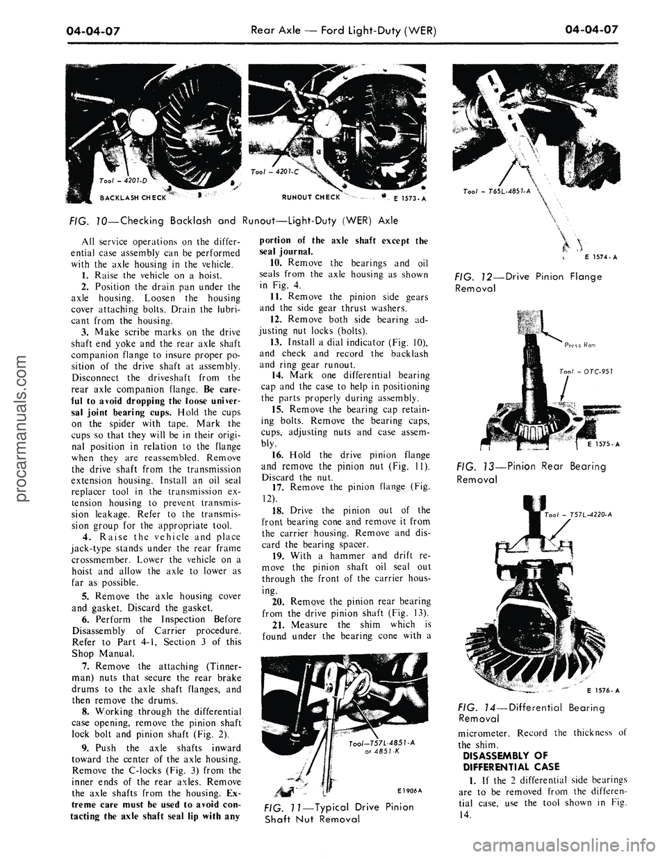
RUNOUT CHECK
E 1573-A
FIG. 70—Checking Backlash and Runout—Light-Duty (WER) Axle
All service operations on the differ-
ential case assembly can be performed
with the axle housing in the vehicle.
1.
Raise the vehicle on a hoist.
2.
Position the drain pan under the
axle housing. Loosen the housing
cover attaching bolts. Drain the lubri-
cant from the housing.
3.
Make scribe marks on the drive
shaft end yoke and the rear axle shaft
companion flange to insure proper po-
sition of the drive shaft at assembly.
Disconnect the driveshaft from the
rear axle companion flange. Be care-
ful to avoid dropping the loose univer-
sal joint bearing cups. Hold the cups
on the spider with tape. Mark the
cups so that they will be in their origi-
nal position in relation to the flange
when they are reassembled. Remove
the drive shaft from the transmission
extension housing. Install an oil seal
replacer tool in the transmission ex-
tension housing to prevent transmis-
sion leakage. Refer to the transmis-
sion group for the appropriate tool.
4.
Raise the vehicle and place
jack-type stands under the rear frame
crossmember. Lower the vehicle on a
hoist and allow the axle to lower as
far as possible.
5.
Remove the axle housing cover
and gasket. Discard the gasket.
6. Perform the Inspection Before
Disassembly of Carrier procedure.
Refer to Part 4-1, Section 3 of this
Shop Manual.
7.
Remove the attaching (Tinner-
man) nuts that secure the rear brake
drums to the axle shaft flanges, and
then remove the drums.
8. Working through the differential
case opening, remove the pinion shaft
lock bolt and pinion shaft (Fig. 2).
9. Push the axle shafts inward
toward the center of the axle housing.
Remove the C-locks (Fig. 3) from the
inner ends of the rear axles. Remove
the axle shafts from the housing. Ex-
treme care must be used to avoid con-
tacting the axle shaft seal lip with any
portion of the axle shaft except the
seal journal.
10.
Remove the bearings and oil
seals from the axle housing as shown
in Fig. 4.
11.
Remove the pinion side gears
and the side gear thrust washers.
12.
Remove both side bearing ad-
justing nut locks (bolts).
13.
Install a dial indicator (Fig. 10),
and check and record the backlash
and ring gear runout.
14.
Mark one differential bearing
cap and the case to help in positioning
the parts properly during assembly.
15.
Remove the bearing cap retain-
ing bolts. Remove the bearing caps,
cups,
adjusting nuts and case assem-
bly.
16.
Hold the drive pinion flange
and remove the pinion nut (Fig. 11).
Discard the nut.
17.
Remove the pinion flange (Fig.
12).
18.
Drive the pinion out of the
front bearing cone and remove it from
the carrier housing. Remove and dis-
card the bearing spacer.
19.
With a hammer and drift re-
move the pinion shaft oil seal out
through the front of the carrier hous-
ing.
20.
Remove the pinion rear bearing
from the drive pinion shaft (Fig. 13).
21.
Measure the shim which is
found under the bearing cone with a
Tool-T57L-485T-A
or 4851-K
El 906A
Tool
-
T6SL-485UA
\
E 1574-A
FIG. 12—Drive Pinion Flange
Removal
1575-A
FIG. 13—Pinion Rear Bearing
Removal
00/
- T57L-4220-A
FIG. 11—Typical Drive Pinion
Shaft Nut Removal
E 1576-A
FIG. 14—Differential Bearing
Removal
micrometer. Record the thickness of
the shim.
DISASSEMBLY OF
DIFFERENTIAL CASE
1.
If the 2 differential side bearings
are to be removed from the differen-
tial case, use the tool shown in Fig.
14.procarmanuals.com
Page 248 of 413
05-01-01
05-01-01
Clutch
GROUP
5
PART
5-1
PAGE
Drive Shaft 05-01-01
PART
5-2
General Clutch Service 05-02-01
PART
5-3
Clutch
PART
5-4
Specifications
PAGE
05-03-01
05-04-01
PART
5-1
Drive Shaft
COMPONENT INDEX
DESCRIPTION
DRIVE SHAFT ANGLE CHECK
DRIVE SHAFT BALANCE CHECK
DRIVE SHAFT BALANCING
(Single Universal Joint)
DRIVE SHAFT DISASSEMBLY
AND
OVERHAUL
Single Universal Joint — Ford Design
Double Cardan Joint — Dana Design
Double Cardan Joint — Saginaw Design
DRIVE SHAFT REMOVAL
AND
INSTALLATION
DRIVE SHAFT RUNOUT CHECK
MODEL APPLICATION
All
Models
01-01
01-01
01-01
01-02
01-01
Ford
01-04
01-04
N/A
N/A
Mercury
01-04
01-04
N/A
N/A
Meteor
01-04
01-04
N/A
N/A
Cougar
01-04
01-04
N/A
N/A
Fairlane
01-04
01-04
N/A
N/A
Falcon
01-04
01-04
N/A
N/A
Montego
01-04
01-04
N/A
N/A
Mustang
01-04
01-04
N/A
N/A
Lincoln-
Continental
N/A
N/A
01-04
N/A
Thunderbird
N/A
N/A
N/A
01-05
Continental-
Mark
III
N/A
N/A
N/A
01-05
A page number indicates that the item
is for the
vehicle listed
at the
head
of
the column.
N/A indicates that
the
item
is not
applicable
to the
vehicle listed.
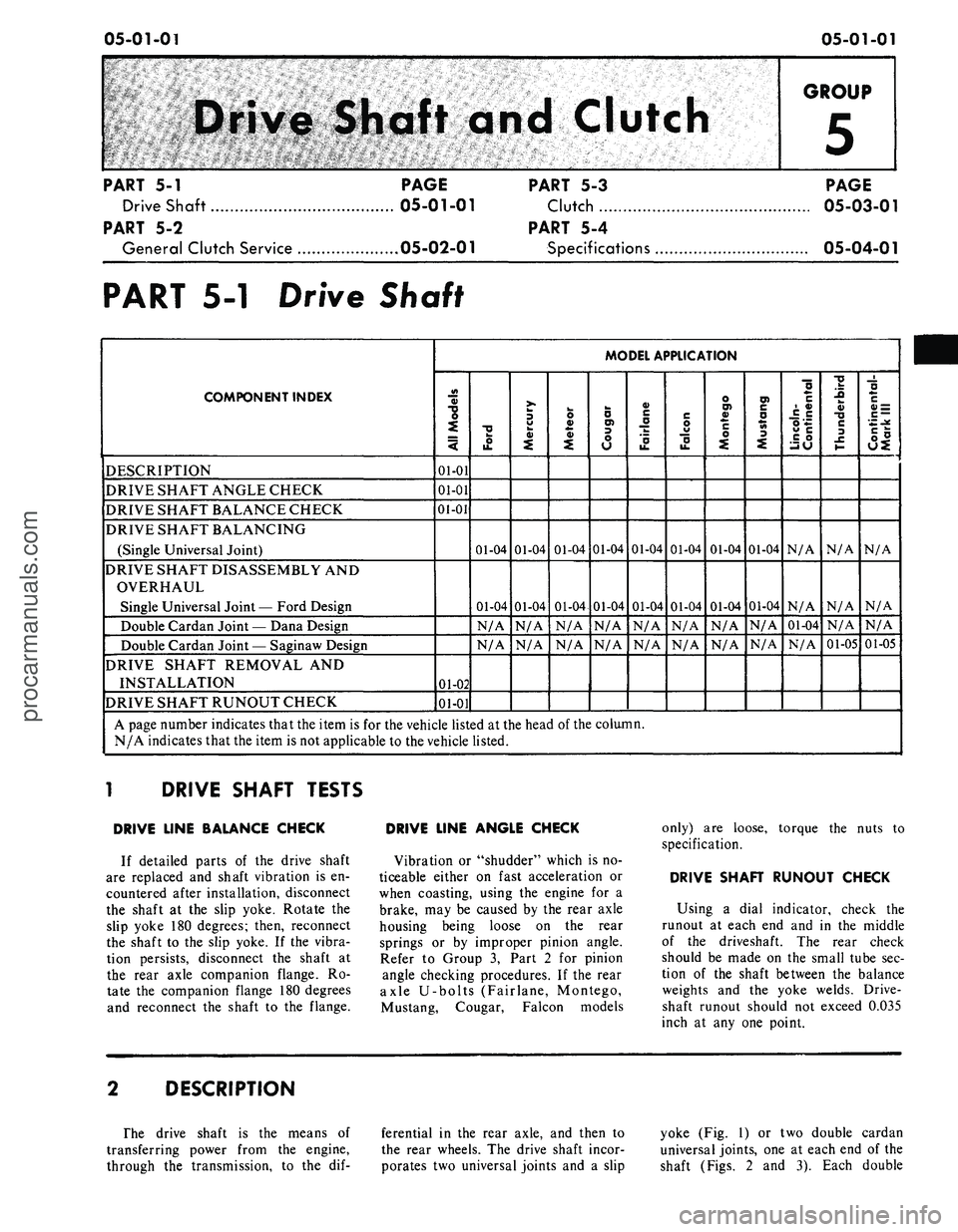
DRIVE SHAFT TESTS
DRIVE LINE BALANCE CHECK
If detailed parts
of the
drive shaft
are replaced
and
shaft vibration
is en-
countered after installation, disconnect
the shaft
at the
slip yoke. Rotate
the
slip yoke
180
degrees; then, reconnect
the shaft
to the
slip yoke.
If the
vibra-
tion persists, disconnect
the
shaft
at
the rear axle companion flange.
Ro-
tate
the
companion flange
180
degrees
and reconnect
the
shaft
to the
flange.
DRIVE LINE ANGLE CHECK
Vibration
or
"shudder" which
is no-
ticeable either
on
fast acceleration
or
when coasting, using
the
engine
for a
brake,
may be
caused
by the
rear axle
housing being loose
on the
rear
springs
or by
improper pinion angle.
Refer
to
Group
3,
Part
2 for
pinion
angle checking procedures.
If the
rear
axle U-bolts (Fairlane, Montego,
Mustang, Cougar, Falcon models
only)
are
loose, torque
the
nuts
to
specification.
DRIVE SHAFT RUNOUT CHECK
Using
a
dial indicator, check
the
runout
at
each
end and in the
middle
of
the
driveshaft.
The
rear check
should
be
made
on the
small tube
sec-
tion
of the
shaft between
the
balance
weights
and the
yoke welds. Drive-
shaft runout should
not
exceed 0.035
inch
at any one
point.
DESCRIPTION
The drive shaft
is the
means
of
transferring power from
the
engine,
through
the
transmission,
to the dif-
ferential
in the
rear axle,
and
then
to
the rear wheels.
The
drive shaft incor-
porates
two
universal joints
and a
slip
yoke
(Fig. 1) or two
double cardan
universal joints,
one at
each
end of the
shaft (Figs.
2 and 3).
Each double
procarmanuals.com
Page 255 of 413
05-02-01
General Clutch Service
05-02-01
PART
5-2
General Clutch Service
COMPONENT INDEX
MODEL APPLICATION
3
a>
1
o>
il
•U
i
!-
II
CLUTCH DISC
Cleaning and Inspection
02-04
02-04
02-04
02-04
02-04
02-04
02-04
02-04
N/A
N/A
N/A
CHECKING FLYWHEEL HOUSING
ALIGNMENT
02-01
02-01
02-01
02-01
02-01
02-01
02-01
02-01
N/A
N/A
N/A
CORRECTING FLYWHEEL HOUSING
ALIGNMENT
02-03
02-03
02-03
02-03
02-03
02-03
02-03
02-03
N/A
N/A
N/A
PILOT BUSHING
Cleaning and Inspection
02-04
02-04
02-04
02-04
02-04
02-04
02-04
02-04
N/A
N/A
N/A
PRESSURE PLATE AND COVER
Cleaning and Inspection
02-04
02-04
02-04
02-04
02-04
02-04
02-04
02-04
N/A
N/A
N/A
RELEASE BEARING
Cleaning and Inspection
02-04
02-04
02-04
02-04
02-04
02-04
02-04
02-04
N/A
N/A
N/A
A page number indicates that the item is for the vehicle listed at the head of the column.
N/A indicates that the item is not applicable to the vehicle listed.
l
FLYWHEEL HOUSING ALIGNMENT
Alignment of the flywheel housing
bore and rear face with the engine
should be checked as a possible cause
of any of the following troubles- ex-
cessive transmission gear wear, ..ans-
mission jumping out of gear, especial-
ly third gear, drive line vibration, ex-
cessive pilot bushing wear, noisy re-
lease bearing, or excessive clutch spin
time.
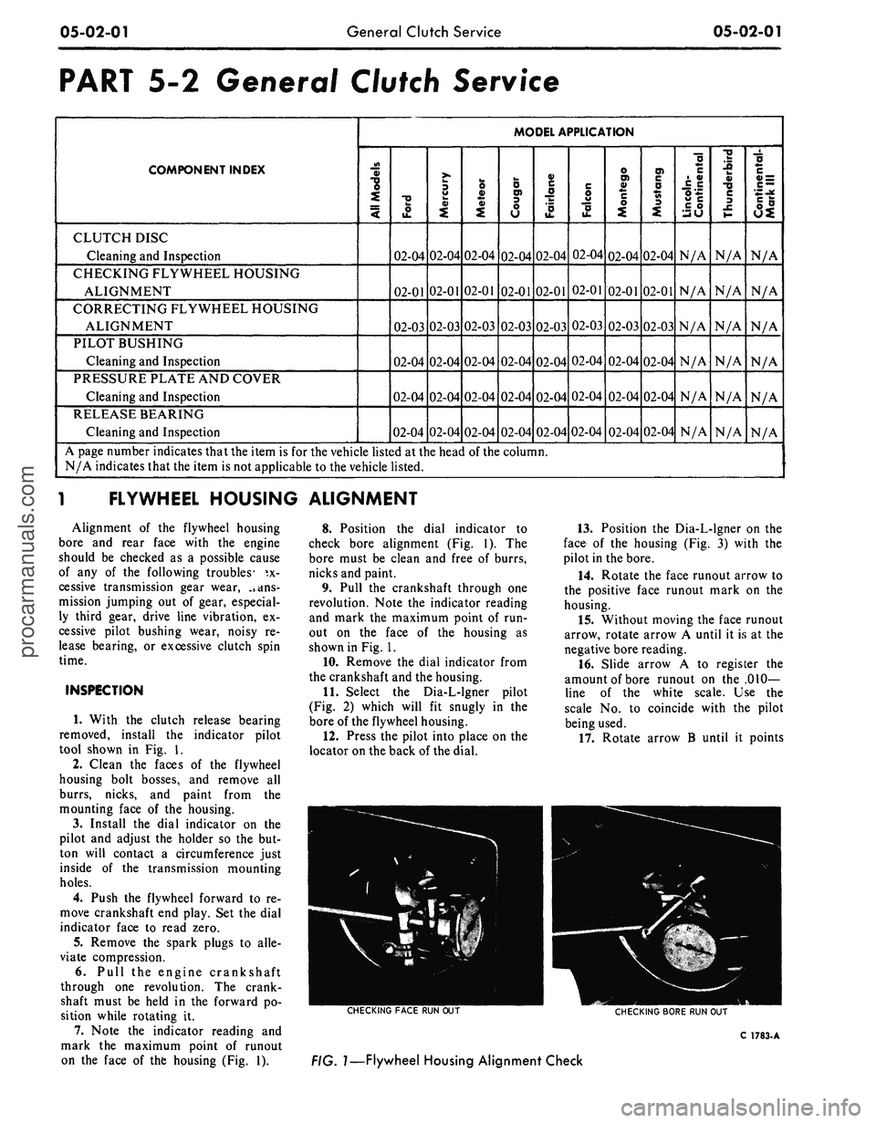
INSPECTION
1. With the clutch release bearing
removed, install the indicator pilot
tool shown in Fig. 1.
2.
Clean the faces of the flywheel
housing bolt bosses, and remove all
burrs, nicks, and paint from the
mounting face of the housing.
3.
Install the dial indicator on the
pilot and adjust the holder so the but-
ton will contact a circumference just
inside of the transmission mounting
holes.
4.
Push the flywheel forward to re-
move crankshaft end play. Set the dial
indicator face to read zero.
5.
Remove the spark plugs to alle-
viate compression.
6. Pull the engine crankshaft
through one revolution. The crank-
shaft must be held in the forward po-
sition while rotating it.
7. Note the indicator reading and
mark the maximum point of runout
on the face of the housing (Fig. 1).
8. Position the dial indicator to
check bore alignment (Fig. 1). The
bore must be clean and free of burrs,
nicks and paint.
9. Pull the crankshaft through one
revolution. Note the indicator reading
and mark the maximum point of run-
out on the face of the housing as
shown in Fig. 1.
10.
Remove the dial indicator from
the crankshaft and the housing.
11.
Select the Dia-L-lgner pilot
(Fig. 2) which will fit snugly in the
bore of the flywheel housing.
12.
Press the pilot into place on the
locator on the back of the dial.
13.
Position the Dia-L-lgner on the
face of the housing (Fig. 3) with the
pilot in the bore.
14.
Rotate the face runout arrow to
the positive face runout mark on the
housing.
15.
Without moving the face runout
arrow, rotate arrow A until it is at the
negative bore reading.
16.
Slide arrow A to register the
amount of bore runout on the .010-
line of the white scale. Use the
scale No. to coincide with the pilot
being used.
17.
Rotate arrow B until it points
CHECKING
FACE
RUN OUT
CHECKING
BORE
RUN OUT
C
1783-
A
FIG.
1—Flywheel
Housing Alignment Checkprocarmanuals.com
Page 257 of 413
05-02-03
General Clutch Service
05-02-03
in the direction of the face runout
arrow and its center line is parallel to
the center line of the face runout
arrow.
18.
Determine the amount of the
face runout on the B arrow scale.
19.
The value of the circular line
beneath the amount of face runout
will be the desired reading. If the
reading is in excess of 0.014 inch the
housing alignment is unacceptable.
20.
Remove the Dia-L-lgner gauge
from the flywheel housing.
21.
Install the spark plugs and con-
nect the wires.
ENGINE IN VEHICLE
Since any change in face alignment
will change bore alignment, it may be
possible to correct bore alignment by
changing face alignment. Face align-
ment can be changed by shimming be-
tween the flywheel housing and en-
gine.
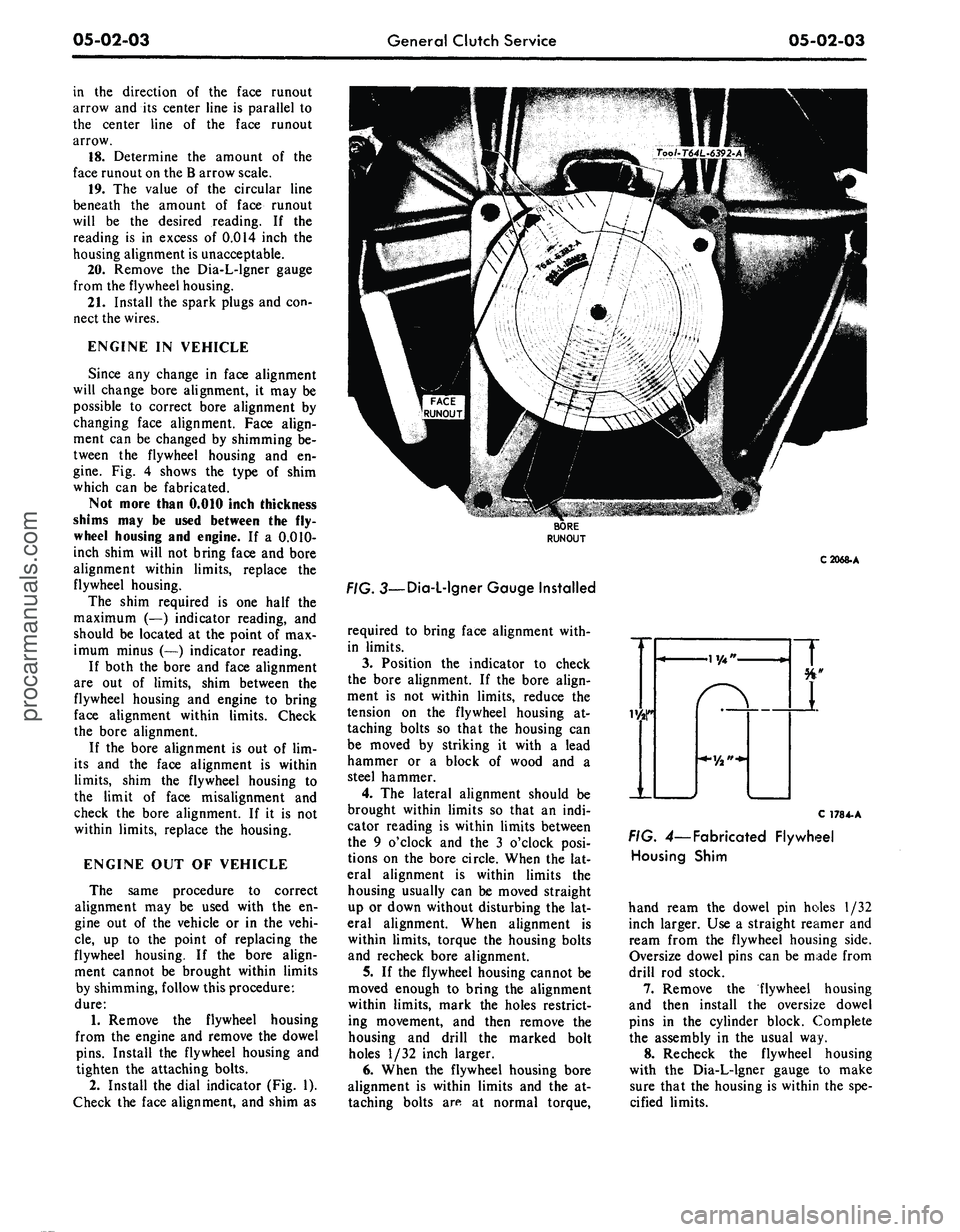
Fig. 4 shows the type of shim
which can be fabricated.
Not more than 0.010 inch thickness
shims may be used between the fly-
wheel housing and engine. If a 0.010-
inch shim will not bring face and bore
alignment within limits, replace the
flywheel housing.
The shim required is one half the
maximum (—) indicator reading, and
should be located at the point of max-
imum minus (—) indicator reading.
If both the bore and face alignment
are out of limits, shim between the
flywheel housing and engine to bring
face alignment within limits. Check
the bore alignment.
If the bore alignment is out of lim-
its and the face alignment is within
limits,
shim the flywheel housing to
the limit of face misalignment and
check the bore alignment. If it is not
within limits, replace the housing.
ENGINE OUT OF VEHICLE
The same procedure to correct
alignment may be used with the en-
gine out of the vehicle or in the vehi-
cle,
up to the point of replacing the
flywheel housing. If the bore align-
ment cannot be brought within limits
by shimming, follow this procedure:
dure:
1.
Remove the flywheel housing
from the engine and remove the dowel
pins.
Install the flywheel housing and
tighten the attaching bolts.
2.
Install the dial indicator (Fig. 1).
Check the face alignment, and shim as
C2068-A
. 3—Dia-L-lgner Gauge Installed
required to bring face alignment with-
in limits.
3.
Position the indicator to check
the bore alignment. If the bore align-
ment is not within limits, reduce the
tension on the flywheel housing at-
taching bolts so that the housing can
be moved by striking it with a lead
hammer or a block of wood and a
steel hammer.
4.
The lateral alignment should be
brought within limits so that an indi-
cator reading is within limits between
the 9 o'clock and the 3 o'clock posi-
tions on the bore circle. When the lat-
eral alignment is within limits the
housing usually can be moved straight
up or down without disturbing the lat-
eral alignment. When alignment is
within limits, torque the housing bolts
and recheck bore alignment.
5.
If the flywheel housing cannot be
moved enough to bring the alignment
within limits, mark the holes restrict-
ing movement, and then remove the
housing and drill the marked bolt
holes 1/32 inch larger.
6. When the flywheel housing bore
alignment is within limits and the at-
taching bolts are at normal torque,
C 178 4-A
FIG. 4— Fabricated Flywheel
Housing Shim
hand ream the dowel pin holes 1/32
inch larger. Use a straight reamer and
ream from the flywheel housing side.
Oversize dowel pins can be made from
drill rod stock.
7.
Remove the flywheel housing
and then install the oversize dowel
pins in the cylinder block. Complete
the assembly in the usual way.
8. Recheck the flywheel housing
with the Dia-L-lgner gauge to make
sure that the housing is within the spe-
cified limits.procarmanuals.com
Page 303 of 413
07-01-12
General Transmission Service
07-01-12
the transmission,
any
metal particles
or clutch plate
or
band material that
may have been carried into
the
cooler
should
be
removed from
the
system
by
flushing
the
cooler
and
lines before
the transmission
is put
back into serv-
ice.
In no
case should
an
automatic
transmission having
a
clutch
or
band
failure
or
other internal trouble result-
ing
in
fluid contamination,
be put
back into service without first flushing
the transmission
oil
cooler.
To flush
the oil
cooler, follow
the
instruct!
on >
provided with
the
Rotun-
da Automatic Transmission Torque
Converter
and
Cooler Cleaner
LRE-
60081.
INSPECTION
TURBINE
AND
STATOR
END
PLAY CHECK
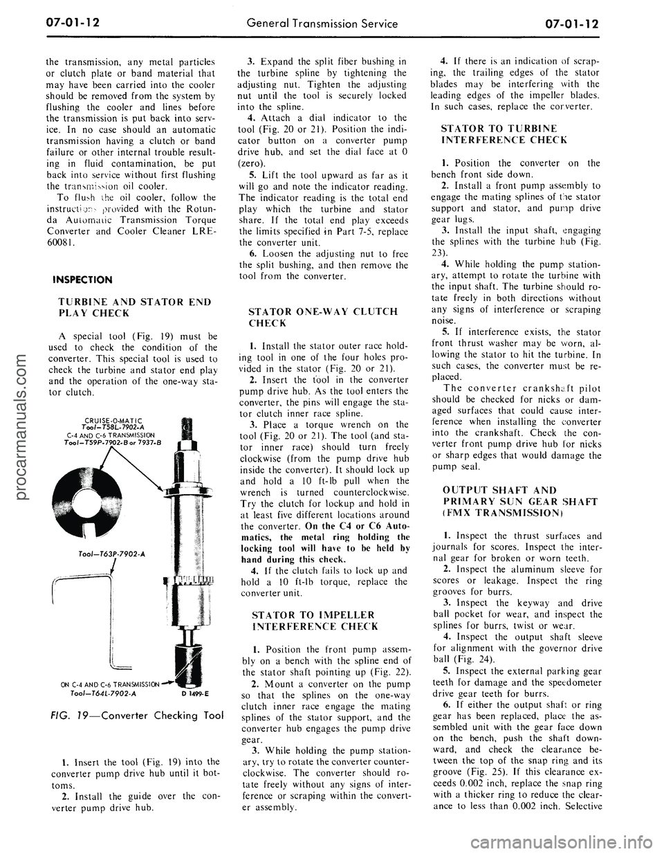
A special tool
(Fig. 19)
must
be
used
to
check
the
condition
of the
converter. This special tool
is
used
to
check
the
turbine
and
stator
end
play
and
the
operation
of the
one-way
sta-
tor clutch.
CRUISE-O-MATIC
Too/-T58L-7902-A
C-4 AND C-6 TRANSMISSION
Tool-T59P.7902.Bor 7937-B
ON C-4 AND C-6 TRANSMISSION
Tool-T64L-7902-A
D
1499-E
FIG. 19—Converter Checking Tool
1.
Insert
the
tool (Fig.
19)
into
the
converter pump drive
hub
until
it
bot-
toms.
2.
Install
the
guide over
the con-
verter pump drive
hub.
3.
Expand
the
split fiber bushing
in
the turbine spline
by
tightening
the
adjusting
nut.
Tighten
the
adjusting
nut until
the
tool
is
securely locked
into
the
spline.
4.
Attach
a
dial indicator
to the
tool (Fig.
20 or
21). Position
the
indi-
cator button
on a
converter pump
drive
hub, and set the
dial face
at 0
(zero).
5.
Lift
the
tool upward
as far as it
will
go and
note
the
indicator reading.
The indicator reading
is the
total
end
play which
the
turbine
and
stator
share.
If the
total
end
play exceeds
the limits specified
in
Part 7-5, replace
the converter unit.
6. Loosen
the
adjusting
nut to
free
the split bushing,
and
then remove
the
tool from
the
converter.
STATOR ONE-WAY CLUTCH
CHECK
1.
Install
the
stator outer race hold-
ing tool
in one of the
four holes
pro-
vided
in the
stator (Fig.
20 or 21).
2.
Insert
the
tool
in the
converter
pump drive hub.
As the
tool enters
the
converter,
the
pins will engage
the sta-
tor clutch inner race spline.
3.
Place
a
torque wrench
on the
tool (Fig.
20 or
21).
The
tool (and
sta-
tor inner race) should turn freely
clockwise (from
the
pump drive
hub
inside
the
converter).
It
should lock
up
and hold
a 10
ft-lb pull when
the
wrench
is
turned counterclockwise.
Try
the
clutch
for
lockup
and
hold
in
at least five different locations around
the converter.
On
the
C4
or C6
Auto-
matics,
the
metal ring holding
the
locking tool will have
to be
held
by
hand during this check.
4.
If the
clutch fails
to
lock
up and
hold
a 10
ft-lb torque, replace
the
converter unit.
STATOR
TO
IMPELLER
INTERFERENCE CHECK
1.
Position
the
front pump assem-
bly
on a
bench with
the
spline
end of
the stator shaft pointing
up
(Fig.
22).
2.
Mount
a
converter
on the
pump
so that
the
splines
on the
one-way
clutch inner race engage
the
mating
splines
of the
stator support,
and the
converter
hub
engages
the
pump drive
gear.
3.
While holding
the
pump station-
ary, try
to
rotate the converter counter-
clockwise.
The
converter should
ro-
tate freely without
any
signs
of
inter-
ference
or
scraping within
the
convert-
er assembly.
4.
If
there
is an
indication
of
scrap-
ing,
the
trailing edges
of the
stator
blades
may be
interfering with
the
leading edges
of the
impeller blades.
In such cases, replace
the
converter.
STATOR
TO
TURBINE
INTERFERENCE CHECK
1.
Position
the
converter
on the
bench front side down.
2.
Install
a
front pump assembly
to
engage
the
mating splines
of
the
stator
support
and
stator,
and
pump drive
gear lugs.
3.
Install
the
input shaft, engaging
the splines with
the
turbine
hub (Fig.
23).
4.
While holding
the
pump station-
ary, attempt
to
rotate
the
turbine with
the input shaft.
The
turbine should
ro-
tate freely
in
both directions without
any signs
of
interference
or
scraping
noise.
5.
If
interference exists,
the
stator
front thrust washer
may be
worn,
al-
lowing
the
stator
to hit the
turbine.
In
such cases,
the
converter must
be re-
placed.
The converter crankshaft pilot
should
be
checked
for
nicks
or dam-
aged surfaces that could cause inter-
ference when installing
the
converter
into
the
crankshaft. Check
the con-
verter front pump drive
hub for
nicks
or sharp edges that would damage
the
pump seal.
OUTPUT SHAFT
AND
PRIMARY
SUN
GEAR SHAFT
(FMX TRANSMISSION)
1.
Inspect
the
thrust surfaces
and
journals
for
scores. Inspect
the
inter-
nal gear
for
broken
or
worn teeth.
2.
Inspect
the
aluminum sleeve
for
scores
or
leakage. Inspect
the
ring
grooves
for
burrs.
3.
Inspect
the
keyway
and
drive
ball pocket
for
wear,
and
inspect
the
splines
for
burrs, twist
or
wear.
4.
Inspect
the
output shaft sleeve
for alignment with
the
governor drive
ball (Fig.
24).
5.
Inspect
the
external parking gear
teeth
for
damage
and the
speedometer
drive gear teeth
for
burrs.
6.
If
either
the
output shaft
or
ring
gear
has
been replaced, place
the as-
sembled unit with
the
gear face down
on
the
bench, push
the
shaft down-
ward,
and
check
the
clearance
be-
tween
the top of the
snap ring
and its
groove
(Fig. 25).
If
this clearance
ex-
ceeds 0.002 inch, replace
the
snap ring
with
a
thicker ring
to
reduce
the
clear-
ance
to
less than 0.002 inch. Selectiveprocarmanuals.com