battery FORD MUSTANG 1969 Volume One Chassis
[x] Cancel search | Manufacturer: FORD, Model Year: 1969, Model line: MUSTANG, Model: FORD MUSTANG 1969Pages: 413, PDF Size: 75.81 MB
Page 44 of 413
02-02-25
Brake System
02-02-25
clearing the pin. Slide the switch com-
pletely onto the pin, and install the
nylon washer as shown in Figs. 29
thru 33. Be careful not to bend or de-
form the switch. Secure these parts to
the pin with the hairpin retainer. Con-
nect the stop light switch wires to the
connector, and install the wires in the
retaining clip.
BRAKE PEDAL
FORD, MERCURY
AND METEOR
Removal
1.
Disconnect the stop light switch
wires at the connector.
2.
Remove the hairpin retainer.
Slide the stop light switch off the
brake pedal pin just far enough for
the switch outer hole to clear the pin,
and then lift the switch straight up-
ward from the pin. Be careful not to
damage the switch during removal.
Slide the master cylinder or booster
push rod and the nylon washers and
bushing off the brake pedal pin (Figs.
26 and 29).
3.
Remove the hairpin type retainer
and washer from the brake pedal
shaft, then remove the shaft, the brake
pedal and the bushings from the pedal
support bracket.
Installation
1.
Apply a coating of SAE 10 En-
gine oil to the bushings and locate
bushings in their proper places on the
pedal assembly and pedal support
bracket (Figs. 26 and 29).
2.
Position the brake pedal assem-
bly to the support bracket, then install
the pedal shaft through the support
bracket and brake pedal assembly. In-
stall the retainer.
3.
Install the inner nylon washer,
the master cylinder or booster push
rod, and the bushing on the brake
pedal pin. Position the switch so that
it straddles the push rod with the
switch slot on the pedal pin and the
switch outer hole just clearing the pin.
Slide the switch completely onto the
pin, and install the nylon washer as
shown in Figs. 26 and 29. Be careful
not to bend or deform the switch. Se-
cure these parts to the pin with the
hairpin retainer.
4.
Connect the stop light switch
wires to the connector, and install the
wires in the retaining clip.
5.
Check the Brake Pedal Free
Height and Travel Measurements,
Part 2-1, Section 1.
FAIRLANE, MONTEGO AND
FALCON—MANUAL-SHIFT
TRANSMISSION
Removal
1.
Remove the clutch pedal assist
spring.
2.
Disconnect the clutch pedal-
to-equalizer rod at the clutch pedal by
removing the retainer and bushing.
3.
Disconnect the stop light switch
wires at the connector.
4.
Remove the switch retainer, and
slide the stop light switch off the
brake pedal pin just far enough for
the switch outer hole to clear the pin.
Then lower the switch away from the
pin.
5. Slide the master cylinder or
booster push rod and the nylon wash-
ers and bushing off from the brake
pedal pin (Figs. 27 and 30).
6. Remove the self-locking pin and
washer from the clutch and brake
pedal shaft, then remove the clutch
pedal and shaft assembly, the brake
pedal assembly, and the bushings from
the pedal support bracket (Figs. 27
and 30).
Installation
1.
Apply a coating of SAE 10 en-
gine oil to the bushings and locate all
bushings in their proper places on the
clutch and brake pedal assemblies.
2.
Position the brake pedal to the
support bracket, then install the clutch
pedal and shaft assembly through the
support bracket and brake pedal as-
sembly. Install the spring clip (Figs.
27 and 30).
3.
Install the clutch pedal assist
spring.
4.
Connect the clutch pedal-
to-equalizer rod to the clutch pedal
assembly with the bushing and the
spring clip retainer. Apply SAE 10
engine oil to the bushing.
5.
Install the inner nylon washer,
the master cylinder or booster push
rod, and the bushing on the brake
pedal pin. Position the switch so that
it straddles the push rod with the
switch slot on the pedal pin and the
switch outer hole just clearing the pin.
Slide the switch completely onto the
pin, and install the outer nylon washer
as shown in Figs. 27 and 30. Secure
these parts to the pin with the
self-
locking pin.
6. Connect the stop light switch
wires to the connector, and install the
wires to the retaining clip.
7.
Adjust the clutch pedal free play
(Group 5) to specification, if required.
8. Check the Brake Pedal Free
Height and Travel Measurements
(Part 2-1, Section 1).
MUSTANG AND COUGAR—
MANUAL-SHIFT
TRANSMISSION
Removal
1.
Disconnect the battery ground
cable from the battery.
2.
Remove the steering column.
Refer to Part 3-4, Section 2 for pro-
cedure.
3.
On non-power brakes, remove
the two cap screws retaining the mas-
ter cylinder to the dash panel and re-
move the two cap screws retaining the
brake pedal support bracket to the
dash panel. On power brakes remove
the two cap screws retaining the
booster to the dash panel.
4.
Working inside the vehicle, se-
cure the clutch pedal against the
bumper stop with a small C-clamp as
shown in Figs. 28 and 31.
5.
Disconnect the clutch pedal-
to-equalizer rod at the clutch pedal by
removing the retainer and bushing.
6. Disconnect the stop light switch
wires at the connector.
7.
Remove the switch retainer and
slide the stop light switch off the
brake pedal pin just far enough for
the switch outer hole to clear the pin.
Then lower the switch away from the
pin.
Remove the master cylinder or
booster push rod, bushing and nylon
washer from the brake pedal pin.
8. Remove the screw retaining the
pedal support bracket to the top inner
cowl bracket (Figs. 28 and 31).
9. Remove the two sheet metal
screws retaining the pedal support
bracket to the dash panel. On power
brakes remove the nuts from the
brake booster studs.
10.
Remove the two screws retain-
ing the pedal support bracket to the
upper cowl brace and lower the pedal
support bracket away from the steer-
ing column studs.
11.
Remove the pedal support
bracket assembly from the vehicle.
12.
Position the pedal and support
bracket assembly in a vise.
13.
Remove the C-clamp to release
the clutch pedal from its bumper stop
and pivot the pedal away from the
bumper.procarmanuals.com
Page 45 of 413
02-02-26
Brake System
02-02-26
14.
Remove the clutch pedal assist
spring.
15.
On non-power brakes, remove
the retainer clip from the clutch and
brake pedal shaft, then remove the
clutch pedal and shaft assembly, the
brake pedal assembly, and the bush-
ings from the pedal support bracket.
On power brakes, remove the retainer
nut from the brake pedal shaft then
remove the pedal shaft, the brake
pedal assembly and the bushings from
the pedal support bracket.
Installation
1. Apply a coating of SAE 10 en-
gine oil to the bushings and locate all
bushings in their proper places on the
clutch and brake pedal assemblies.
2.
On non-power brakes, position
the brake pedal to the pedal support
bracket, then install the clutch pedal
and shaft assembly through the sup-
port bracket and brake pedal assem-
bly. On power brakes position the
brake pedal to the pedal support
bracket, then install the pedal shaft
and nut.
3.
Install the clutch pedal assist
spring and pivot the clutch pedal
against its bumper stop. Secure the
pedal to the stop with a small C-
clamp as shown in Figs. 28 and 31.
4.
Position the pedal support
bracket assembly to the dash panel,
and to the steering column retainer
studs.
5.
Align the pedal support bracket
holes with the holes in the dash panel
and install the two attaching sheet
metal screws. On power brakes install
the nuts on the brake booster studs.
6. Install the two cap screws at-
taching the pedal support bracket to
the upper cowl bracket.
7. Install the cap screw attaching
the pedal support bracket to the top
inner cowl bracket (Figs. 28 and 31).
8. Install the inner nylon washer,
the master cylinder push rod, and the
bushing on the brake pedal pin. Posi-
tion the stop light switch so that it
straddles the push rod with the switch
slot on the pedal pin and the switch
outer hole just clearing the pin. Slide
the switch completely onto the pin,
and install the outer nylon washer as
shown in Figs. 28 and 31. Secure
these parts to the pin with the
self-
locking retainer.
9. Connect the stop light switch
wires to the connector.
10.
Connect the clutch pedal-
to-equalizer rod to the clutch pedal
assembly with the bushing and the
spring clip retainer. Apply SAE 10
engine oil to the bushing. Remove the
C-clamp from the clutch pedal.
11.
Working from the engine side
of the dash panel, on non-power
brakes, install the two cap screws at-
taching the pedal support bracket to
the dash panel. Then install the two
screws attaching the master cylinder
to the dash panel. On power brakes
install the cap screws retaining the
brake booster to the dash panel.
12.
Install the steering column.
Refer to Part 3-4, Section 2 for pro-
cedure.
13.
Adjust the clutch pedal free
play (Group 5) to specification, if re-
quired.
14.
Check the Brake Pedal Free
Height and Travel Measurements
(Part 2-1, Section 1).
15.
Connect the ground cable to the
battery.
FAIRLANE, MONTEGO,
FALCON, MUSTANG
AND COUGAR-
AUTOMATIC TRANSMISSION
Removal
1. Disconnect the stop light switch
wires at the connector.
2.
Remove the self-locking pin and
slide the stop light switch off the
brake pedal pin just far enough for
the switch outer hole to clear the pin.
Then lower the switch away from the
pin. Slide the master cylinder or
booster push rod and the nylon wash-
ers and bushing off from the brake
pedal pin (Figs. 27, 28, 30 and 31).
3.
On all vehicles except Mustang
and Cougar with power brakes, re-
move the self-locking pin and washer
from the brake pedal shaft, then re-
move the shaft, the brake pedal as-
sembly and the bushings from the
pedal support bracket. On Mustang
and Cougar vehicles with power
brakes, remove the locknut and bolt
from the pedal. Remove the pedal as-
sembly from the support bracket (Fig.
3).
Installation
1. Apply a coating of SAE 10 en-
gine oil to the bushings and locate all
the bushings in their proper places on
the pedal assembly and pedal support
bracket (Figs. 27, 28, 30 and 31).
2.
Position the brake pedal assem-
bly to the support bracket, then install
the pedal shaft or bolt through the
support bracket and brake pedal as-
sembly. Install the retainer or locknut.
3.
Install the inner nylon washer,
the master cylinder or booster push
rod, and the bushing on the brake
pedal pin. Position the switch so that
it straddles the push rod with the
switch slot on the pedal pin, and the
switch outer hole just clearing the pin.
Slide the switch completely onto the
pin, and install the outer nylon washer
as shown in Figs. 27, 28, 30 and 31.
Secure these parts to the pin with the
self-locking pin.
4.
Connect the stop light switch
wires to the connector, and install the
wires in the retaining clip.
Check the Brake Pedal Free Height
and Travel Measurements, Part 2,
Section 1.
THUNDERBIRD
AND
CONTINENTAL MARK
III
Removal
1.
Loosen the booster mounting
nuts.
2.
Disconnect the stop light switch
wires at the connector.
3.
Remove the hairpin retainer.
Slide the stop light switch off from
the brake pedal pin just far enough
for
the
switch outer hole
to
clear
the
pin,
and then lift the switch straight
upward from the pin. Slide the master
cylinder push rod and the nylon wash-
ers and bushing off from the brake
pedal pin (Fig. 32).
4.
Remove the pivot bolt and nut
that holds the pedal to the pedal sup-
port bracket. Remove the brake pedal
assembly from the pedal support
bracket, and remove the bushings.
Installation
1. Apply a coating of SAE 10 en-
gine oil to the bushings and locate all
the bushings in their proper places on
the pedal assembly (Fig. 32).
2.
Install the brake pedal assembly
and bushings to the support bracket,
and then install the pivot bolt through
the support bracket and brake pedal
assembly. Install the pivot bolt nut
and torque to specifications.
3.
Install the inner nylon washer,
the master cylinder push rod, and the
bushing on the brake pedal pin. Posi-
tion the switch so that it straddles the
push rod with the switch slot on the
pedal pin and the switch outer hole
just clearing the pin. Slide the switch
completely onto the pin, install the
outer nylon washer as shown in Fig.
32.
Secure these parts to the pin with
the hairpin retainer.procarmanuals.com
Page 46 of 413
02-02-27
Brake System
02-02-27
4.
Connect the stop light switch
wires to the connector, and install the
wires in the retaining clip.
5.
Torque the booster mounting
nuts to specifications.
LINCOLN CONTINENTAL
Removal
1.
Disconnect the battery ground
cable from the battery.
2.
It is necessary to obtain clear-
ance to remove vacuum hoses and the
electrical connector to the temperature
heat control box. Remove the two
screws retaining the relay to the fend-
er and push the relay aside. Discon-
nect the vacuum hoses and connector
at the heat control box.
3.
Working under the instrument
panel, disconnect the vacuum hoses,
wires and retaining clip from the tem-
perature heat control box. Remove the
two screws securing the temperature
control box to the dash panel.
4.
Remove the lower control hous-
ing retaining screws (6). Disconnect
the wire harnesses at the lower control
panel and place the panel aside. Re-
move the wire harness shield. Remove
the wire harness clip. Position the
wire harness aside. Remove the tem-
perature control box and position it
aside.
5.
Remove the hair-pin type retain-
er. Slide the stop light switch off the
brake pedal pin just far enough for
the switch outer hole to clear the pin.
Lift the switch upward from the pin.
Slide the master cylinder push rod,
nylon washers and bushing off the
brake pedal pin.
6. Remove the pivot bolt and nut
that holds the pedal to the pedal sup-
port bracket. Remove the brake pedal
assembly from the support bracket
and remove the bushings.
7.
If required, remove the brake
pedal pad retaining nuts and remove
the brake pedal pad.
Installation
1.
If the brake pedal pad was re-
moved, position the pad on the pedal.
Install the pad retaining nuts and tor-
que them to specification.
2.
Apply SAE 10 engine oil to the
bushings and locate all the bushings in
their proper places on the pedal as-
sembly.
3.
Install the brake pedal assembly
and bushings to the support bracket,
and then install the pivot bolt through
the support bracket and pedal assem-
bly. Install the pivot bolt nut and tor-
que it to specification.
4.
Install the inner nylon washer,the
master cylinder push rod link, and the
bushing on the brake pedal pin. Posi-
tion the switch so that it straddles the
push rod link with the switch slot on
the pedal and the switch outer hole
just clearing the pin. Install the outer
nylon washer as shown in Fig. 33. In-
stall the hair-pin type retainer on the
brake pedal pin.
5.
Connect the stop light switch
wires to the connector, and install the
wires in the retaining clip.
6. Position the wire harness and
clip on the temperature control box
and install the retaining screw. Posi-
tion the temperature control box to
the dash panel and install the two re-
taining bolts.
7.
Connect the vacuum lines and
the electrical connector to the control
box. Position the wire harness to the
control box and install the retaining
clip.
8. Position the wire harness shield
and install two retaining bolts.
9. Connect the wire harnesses to
the lower control panel and install the
retaining screws.
10.
Working within the engine
compartment, connect the wire con-
nector to the temperature heat control
box.
11.
Position the relay to the fender
apron and install the retaining bolts.
12.
Connect the ground cable to the
battery.
13.
Check the brakes and light
switch for proper operation. Close the
hood.
PARKING BRAKE CONTROL
ASSEMBLY
FORD, MERCURY
AND METEOR
Removal
Refer to Fig. 34.
1.
Make sure the parking brake is
fully released.
2.
Remove all tension from the rear
cables by backing off the adjusting nut
from the equalizer.
3.
Remove the roll pin that secures
the release knob to the cable and re-
move the knob.
4.
Remove the nut that secures the
release cable to the instrument panel
and remove the cable from the rear of
the instrument panel.
5.
Remove the two nuts attaching
the control assembly to the dash
panel.
6. Remove the cap screw attaching
the control assembly to the cowl side
bracket.
7.
Disconnect the hose to the park-
ing brake vacuum unit, if so equipped.
8. Remove the front cable assembly
retainer clip from the cable assembly
and disconnect the cable ball from the
control clevis.
9. Remove the control assembly
from the vehicle.
Installation
1.
Position the control assembly in
the vehicle.
2.
Fit the cable assembly through
its mounting hole and install the re-
taining clip. Connect the cable ball to
the control clevis.
3.
Connect the vacuum hose to the
parking brake unit, if so equipped.
4.
Install the attaching cap screw to
the cowl side bracket. Do not tighten.
5.
Install the two control assemb-
ly-to-dash panel nuts. Tighten the nuts
and the cap screw to specifications.
6. Insert the release cable into the
instrument panel and install the re-
taining nut.
7.
Install the release knob on the
cable with the roll pin.
8. Check the operation of the park-
ing brake. Adjust the parking brake
as required.
FAIRLANE, MONTEGO
AND FALCON
Removal
Refer to Fig. 35.
1.
Make sure the parking brake is
completely released.
2.
Remove all tension from the rear
cables by backing off the jam nut and
adjusting nut from the equalizer.
3.
Working inside the vehicle, re-
move the four bolts and one nut re-
taining the left air vent and cable as-
sembly to the dash and instrument
panels. Remove the vent assembly.
4.
Remove the parking brake front
cable ball retaining clip from the clev-
is.
5.
Disconnect the cable ball from
the notch in the brake clevis.
6. Remove the three screws that at-
tach the control assembly to the left
cowl inner side panel.procarmanuals.com
Page 49 of 413
02-02-30
Brake System
02-02-30
7.
Disconnect the wire lead at the
parking brake warning light switch
and remove the control assembly.
Installation
1.
Connect the wire lead to the
parking brake warning light switch.
2.
Position the control assembly to
the cowl inner side panel and install
the three attaching screws.
3.
Connect the ball-end of the park-
ing brake front cable assembly to the
control assembly, and install the hair-
pin retainer.
4.
Position the cable ball in the
notch in the brake clevis.
5.
Position the left air vent assem-
bly to the dash and instrument panels.
Install the four bolts and one nut re-
taining the air vent to the panels.
6. Check the operation of the park-
ing brake. Adjust the parking brake.
MUSTANG AND COUGAR
Removal
Refer to Fig. 36.
1.
Make sure the parking brake is
completely released,
2.
Remove all tension from the rear
cables by backing off the jam nut and
adjusting nut from the equalizer.
3.
Disconnect the wire lead at the
parking brake warning light switch (if
so equipped).
4.
Remove the parking brake front
cable ball retaining clip from the clev-
is.
5.
Remove the parking brake warn-
ing light switch and attaching screw (if
so equipped).
6. Disconnect the cable ball from
the notch in the brake clevis.
7.
Remove the three screws that at-
tach the control assembly to the left
cowl inner side panel.
8. Pull the control away from the
cowl, panel. Remove the hair-pin re-
tainer securing the front cable assem-
bly to the control assembly. Remove
the control assembly
Installation
1.
Connect the ball-end of the park-
ing brake front cable assembly to the
control assembly, and install the hair-
pin retainer.
2.
Position the control assembly to
the cowl inner side panel and install
the three attaching screws.
3.
Position the parking brake warn-
ing light switch and install the attach-
ing screw. Connect the parking brake
warning light switch wire lead (if vehi-
cle is so equipped).
4.
Position the cable ball in the
notch in the brake clevis.
5.
Check the operation of the park
ing brake. Adjust the parking brake.
THUNDERBIRD AND
CONTINENTAL MARK III
Removal
Refer to Fig. 37.
1.
Remove the two nuts retaining
the control to the dash panel.
2.
Remove two screws from the left
scuff plate.
3.
Remove one screw retaining the
left cowl trim panel and remove the
panel.
4.
Remove the two screws retaining
the left air duct and remove the air
duct.
5.
Remove the two screws retaining
the dimmer switch and position the
switch out of the way.
6. Remove the clip retaining the
cable assembly to the control.
7.
Disconnect the cable ball from
the control clevis.
8. Disconnect the vacuum hose at
the brake release.
9. Remove the bolt retaining the
control to the cowl side bracket and
remove the control.
Installation
1.
Position the parking brake con-
trol in the vehicle.
2.
Install the cable assembly in the
control and connect the cable ball to
the control clevis.
3.
Install the clip retaining the
cable to the control.
4.
Install the bolt retaining the con-
trol to the cowl side bracket.
5.
Connect the vacuum hose to the
parking brake release vacuum motor.
6. Position the dimmer switch and
install the retaining screws.
7.
Position the air duct and install
the retaining screws.
8. Position the cowl trim panel and
install the retaining screw.
9. Install the two scuff plate screws.
10.
Install the two nuts retaining
the control to the dash panel.
11.
Adjust the parking brakf
LINCOLN CONTINENTAL
Removal
Refer to Fig. 38.
1.
Raise the vehicle on a hoist.
2.
Loosen the parking brake cable
adjusting nut, remove the return
spring and remove the cable ball end
from the equalizer.
3.
Lower the vehicle.
4.
Disconnect the battery.
5.
Disconnect the wire harness con-
nector and two vacuum hoses at the
Automatic Temperature Control box.
6. Working inside the vehicle, re-
move the windshield wiper control
knob and bezel from the lower control
panel.
7.
Remove the screws retaining the
lower control panel. Lower the control
panel and disconnect wire harnesses
and vacuum hoses. Position the con-
trol panel aside.
8. Remove the screw retaining the
plastic wire cover and place 'the cover
aside.
9. Disconnect three vacuum hoses
and the wiring harness at the Auto-
matic Temperature Control box.
10.
Remove the two screws retain-
ing the Automatic Temperature Con-
trol box to the dash panel and remove
the box for clearance.
11.
Disconnect the ball end of the
cable from the control clevis.
12.
Remove the four bolts retaining
the control to the dash panel and
lower instrument panel flange.
13.
Disconnect the vacuum release
hose from the control and remove the
control assembly from the vehicle.
Installation
1.
Position the control assembly to
the dash panel and instrument panel
flange and install the four retaining
screws.
2.
Connect the vacuum release hose
to the control assembly.
3.
Connect the cable ball to the
control clevis.
4.
Position the Automatic Temper-
ature Control box to the dash panel
and install the retaining screws.
5.
Connect the wiring harness and
vacuum hoses to the Automatic Tem-
perature Control box.
6. Position the plastic wire covei
and install the retaining screw.
7.
Connect the wire harnesses and
vacuum lines to the lower control
panel and position the panel to the inprocarmanuals.com
Page 53 of 413
02-02-34
Brake System
02-02-34
strument panel. Install the lower con-
trol panel retaining screws.
8. Install the windshield wiper con-
trol bezel and knob.
9. Working in the engine compart-
ment connect the wire harness and
vacuum hoses to the Automatic Tem-
perature Control box.
10.
Connect the battery cable.
11.
Raise the vehicle on a hoist.
12.
Connect the cable ball to the
equalizer and install the equalizer
lever return ^spring.
13.
Adjust the parking brake cable
tension.
14.
Lower the vehicle.
PARKING BRAKE ACTUATOR—
TO CONTROL CABLE
FORD, MERCURY
AND METEOR
Removed
1.
Raise the vehicle on a hoist.
2.
Loosen the actuator lever to
equalizer cable adjusting nut at the
equalizer (Fig. 34).
3.
Disconnect the cable ball from
the clevis on the actuator lever.
4.
Remove spring clip that retains
the cable to the frame.
5.
From inside of passenger com-
partment, remove spring clip that re-
tains the cable to the parking brake
control. Disconnect the cable ball
from the control assembly.
6. Remove the cable assembly from
the vehicle.
Installation
1.
Position the cable through the
provided openings and in the approxi-
mate final installation position.
2.
Install the hairpin retainer on the
cable at the frame crossmember.
3.
Connect the ball end of the cable
to the parking brake control. Install
the cable-to-control hairpin retaining
clip.
4.
Position the cable seal at the
dash panel, and slide the retaining clip
upward to seal the cable at the dash
opening.
5.
Connect the ball end of the cable
to the clevis on the actuator lever.
6. Adjust the parking brake (Part
2-1,
Section 2).
7.
Lower vehicle on hoist.
THUNDERBIRD AND
CONTINENTAL MARK III
Removal
Refer to Fig. 37.
1.
Partially raise the vehicle.
2.
Back off the adjusting nut at the
equalizer to relieve the tension on the
cable.
3.
Remove the spring at the actua-
tor lever and disconnect the control
cable from the clevis on the lever.
4.
Remove the clip retaining the
control cable assembly to
thq*.
frame
bracket. B
5.
Attach a length of wire to the
control cable.
6. Working inside the vehicle re-
move two screws retaining the left
scuff plate.
7.
Remove one screw and remove
the left cowl side trim panel.
8. Remove the two screws retaining
the left air duct to the inner panel and
remove the air duct.
9. Remove the two screws retaining
the dimmer switch and position the
dimmer switch back out of the way.
10.
Remove the clip retaining the
cable assembly to the control and re-
move the cable ball from the control
clevis.
11.
Pull the cable up through the
opening in the dash panel and remove
the cable from the length of wire.
Installation
1.
Attach the cable to the length of
wire and pull the cable down through
the opening in the dash panel.
2.
Position the upper end of the
control cable to the control. Connect
the cable ball to the control clevis and
install the clip retaining the cable
housing to the control.
3.
Remove the length of wire from
the cable assembly and position the
cable in the frame bracket. Install the
retainer,
4.
Connect the cable ball to the
clevis on the actuator lever and install
the actuator lever spring.
5.
Adjust the parking brake.
6. Reposition the dimmer switch
and install the retaining screws.
7.
Position the air duct to the inner
panel and install the retaining screws.
& Position the cowl side trim panel
and install the retaining screw.
9. Install the two screws in the
scuff plate.
PARKING BRAKE
EQUALIZER TO CONTROL
CABLE
FAIRLANE, MONTEGO
AND FALCON
Removal
Refer to Fig. 35.
1.
Make certain the parking brake
is fully released.
2.
Raise the vehicle on a hoist. Re-
move the two nuts that attach the
cable to the equalizer. Remove the
equalizer, spring seat and spring.
3.
Remove the hairpin retainer
holding the cable assembly to i:he body
bracket and remove the cable from
the slot in the bracket.
4.
Lower the vehicle partially.
5.
Remove the hairpin retainer
which retains the cable assembly to
the control.
6. Remove the cable bolt retaining
clip from the control clevis and dis-
connect the cable ball from the clevis.
7.
Pull the cable down through the
opening in the floor pan and frame
side rail.
Installation
1.
Route the new cable through
the frame side rail and up through
the opening in the floor pan. Pull the
cable up into position.
2.
Connect the cable ball in the con-
trol clevis.
3.
Insert the cable housing into
the control and install the hairpin re-
tainer.
4.
Raise the vehicle.
5.
Position the cable in the body
bracket and install the hairpin re-
tainer.
6. Position the spring, spring re-
tainer and equalizer on the cable and
install the two nuts.
7.
Adjust the parking brake.
MUSTANG AND COUGAR
Removal
Refer to Fig. 36.
1.
Make certain the parking brake
is fully released.
2.
Raise the vehicle on a hoist. Re-
move the two nuts that attach the
cable to the equalizer. Remove the
equalizer spring seat and spring.
3.
Remove the hairpin retainer
holding the cable assembly to the
body bracket and pull the cable out
of the side rail access holes.procarmanuals.com
Page 115 of 413
03-05-02
Steering Columns
And
Linkage
03-05-02
which also will shear away during
im-
pact.
TILT STEERING COLUMNS
The steering column
is of the col-
lapsible type
to
lessen
the
possibility
of injury
to the
driver
of the
vehicle
should
he
become involved
in an
acci-
dent.
The
lower
end of the
steering
column tube
at the
bellows area will
collapse approximately
six
inches
upon
a
hard impact.
The shift tube
and the
steering shaft
are provided with plastic dowels
and
will shear
and
allow them
to
collapse
in proportion
to the
outer tube upon
impact.
Once
the
steering column
has
been
collapsed,
a
complete
new
column
must
be
installed.
The tilt column features nine driv-
ing positions (four
up and
four down
from
a
center position).
The
.column
also features
a
turn signal switch with
a lane-changer position turn indicating
position
and
emergency warning flash-
er control.
TILT-AWAY STEERING COLUMNS
The tilt-away steering column
fea-
tures nine driving positions (four
up
and four down from
a
center position)
and
a
tilt-away position that
is
auto-
matically accomplished
on
Mustang
and Cougar models when
the
ignition
key
is
turned
to the
OFF
position
and
the left door
is
opened.
On
Thunder-
bird models,
the
tilt-away occurs when
the shift lever
is
placed
in
PARK
and
the driverns door
is
opened.
The steering column
is of the col-
lapsible type
to
lessen
the
possibility
of injury
to the
driver
of the
vehicle
should
he
become involved
in an
acci-
dent.
The
lower
end of the
steering
column tube
at the
bellows area will
collapse approximately
six
inches
upon
a
hard impact.
The shift tube
and the
steering shaft
are provided with plastic dowels
and
will shear
and
allow them
to
collapse
in proportion
to the
outer tube upon
impact.
Once
the
steering column
has
been
collapsed,
a
complete
new
column
must
be
installed along with mounting
brackets which will also shear away
during impact.
IN-VEHICLE ADJUSTMENTS
AND
REPAIRS
STEERING WHEEL SPOKE
POSITION ADJUSTMENT
When
the
steering gear
is on the
high point,
the
front wheels should
be
in
the
straight-ahead position
and the
steering wheel spokes should
be in
their normal position with
the
Pitman
arm pointing directly forward.
If the
spokes
are not in
their normal posi-
tion, they
can be
adjusted without
dis-
turbing
the
toe-in adjustment (Part
3-1).
STEERING WHEEL
REPLACEMENT
1.
Disconnect
the
negative cable
from
the
battery.
2.
Working from
the
underside
of
the steering wheel spoke, remove
the
crash
pad
attaching screws. Lift
the
crash
pad
from
the
wheel.
(On
Conti-
nental Mark
III
models,
pry out the
crash
pad
insert
and
remove
the two
screws that secure
the
crash
pad. Re-
move
the
crash
pad. On
models
equipped with steering wheel mounted
speed controls, refer
to
Group
16 for
removal instructions). Remove
the
horn ring
(if so
equipped)
by
turning
it counterclockwise.
3.
Remove
the
steering wheel
nut,
and then remove
the
steering wheel
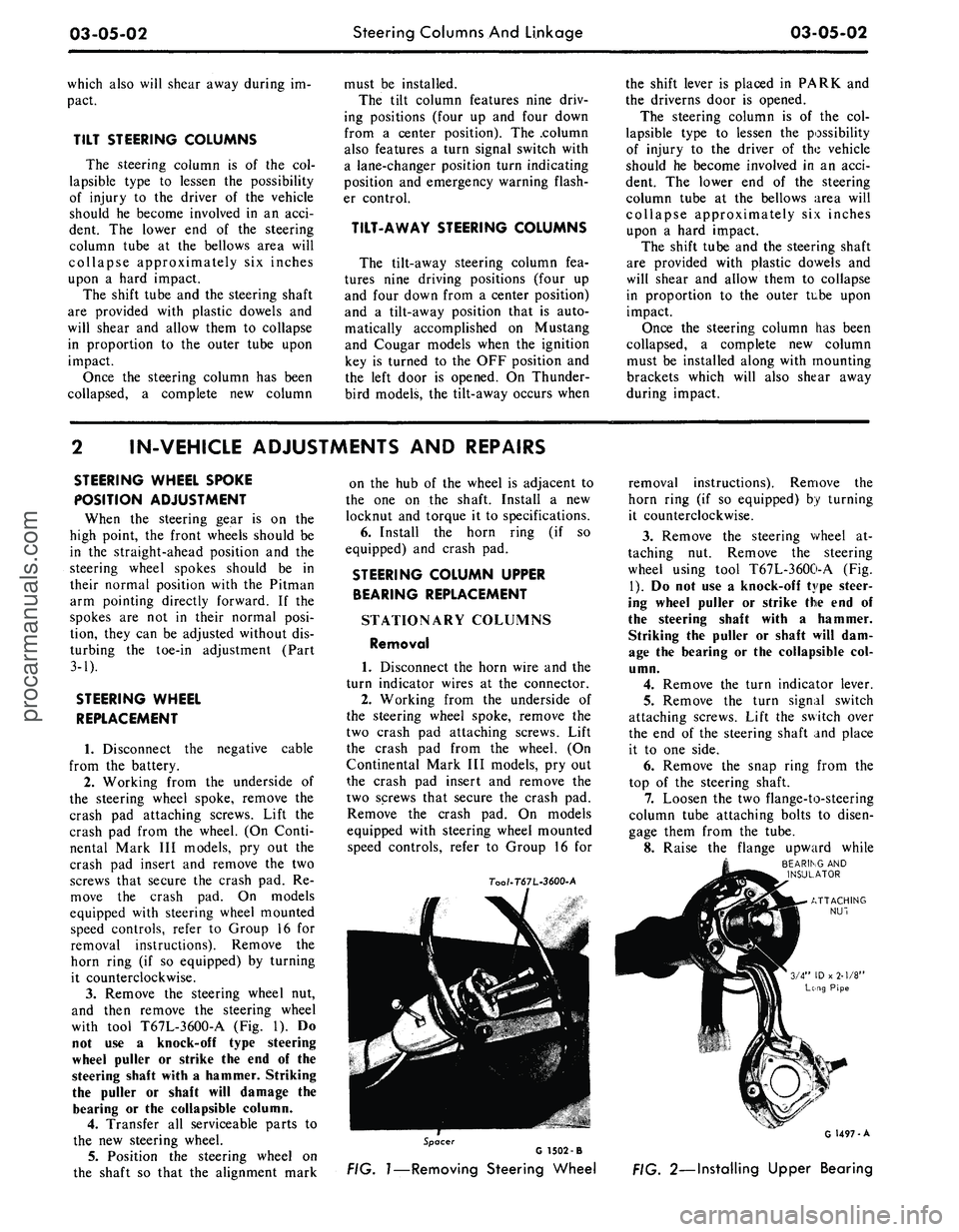
with tool T67L-3600-A
(Fig. 1). Do
not
use a
knock-off type steering
wheel puller
or
strike
the end of the
steering shaft with
a
hammer. Striking
the puller
or
shaft will damage
the
bearing
or the
collapsible column.
4.
Transfer
all
serviceable parts
to
the
new
steering wheel.
5.
Position
the
steering wheel
on
the shaft
so
that
the
alignment mark
on
the hub of the
wheel
is
adjacent
to
the
one on the
shaft. Install
a new
locknut
and
torque
it to
specifications.
6. Install
the
horn ring
(if so
equipped)
and
crash
pad.
STEERING COLUMN UPPER
BEARING REPLACEMENT
STATIONARY COLUMNS
Removal
1. Disconnect
the
horn wire
and the
turn indicator wires
at the
connector.
2.
Working from
the
underside
of
the steering wheel spoke, remove
the
two crash
pad
attaching screws. Lift
the crash
pad
from
the
wheel.
(On
Continental Mark
III
models,
pry out
the crash
pad
insert
and
remove
the
two screws that secure
the
crash
pad.
Remove
the
crash
pad. On
models
equipped with steering wheel mounted
speed controls, refer
to
Group
16 for
7oo/-T67L-3600-A
removal instructions). Remove
the
horn ring
(if so
equipped)
by
turning
it counterclockwise.
3.
Remove
the
steering wheel
at-
taching
nut.
Remove
the
steering
wheel using tool T67L-3600-A
(Fig.
1).
Do not use a
knock-off type steer-
ing wheel puller
or
strike
the end of
the steering shaft with
a
hammer.
Striking
the
puller
or
shaft will
dam-
age
the
bearing
or the
collapsible
col-
umn.
4.
Remove
the
turn indicator lever.
5.
Remove
the
turn signal switch
attaching screws. Lift
the
switch over
the
end of the
steering shaft
and
place
it
to one
side.
6. Remove
the
snap ring from
the
top
of the
steering shaft.
7.
Loosen
the two
flange-to-steering
column tube attaching bolts
to
disen-
gage them from
the
tube.
8. Raise
the
flange upward while
BEARING
AND
INSULATOR
Spacer
G 1502 -B
FIG.
1—Removing
Steering Wheel
G 1497-A
FIG. 2—Installing Upper Bearingprocarmanuals.com
Page 116 of 413
03-05-03
Steering Columns And Linkage
03-05-03
tapping the steering shaft lightly with
a plastic hammer to free the bearing
and flange from the shaft.
9. Remove the bearing and insula-
tor from the flange.
Installation
1.
Install flange bolts (square head)
in flange if they were removed. Turn
the nuts onto the bolts one complete
turn only.
2.
Position the flange onto the
steering column tube.
3.
Engage the two flange bolt heads
with the square holes in the column
tube,
then tighten the two attaching
nuts to specification.
4.
Position the bearing and insula-
tor on the shaft. Work it down onto
the shaft as far as possible, then place
a piece of 3/4 ID x 2 1/8 inch pipe
over the end of the shaft and install
the steering wheel attaching nut (Fig.
2).
5.
Tighten the nut until the bearing
is seated in the flange, then remove
the nut and pipe from the shaft.
6. Position the turn signal switch
on the flange and install the three at-
taching screws.
7.
Make certain that the wheels are
in the straight ahead position. Place
the steering wheel on the steering
shaft with the spokes in the horizontal
position. Install and torque the attach-
ing nut to specification.
8. Secure the crash pad to the
steering wheel with the two attaching
screws.
9. Connect the horn and turn signal
wires.
10.
Install the turn signal lever.
TILT WHEEL COLUMNS
Removal
1.
Disconnect the negative cable
from the battery.
2.
Remove the steering wheel with
tool T67L-3600-A (Fig. 1). Install the
spring, shipping spacer (3/4 x 1 1/8-
inch pipe) and a steering wheel attach-
ing nut on the shaft. Do not use a
knock-off type steering wheel puller or
strike the end of the steering shaft
with a hammer. Striking the puller or
shaft will damage the bearing or the
collapsible column.
3.
Remove the turn indicator lever
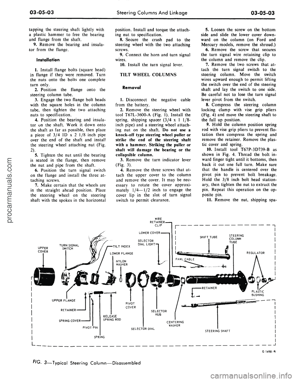
(Fig. 3).
4.
Remove the three screws that at-
tach the upper cover to the column
and remove the cover. It may be nec-
essary to rotate the cover approxi-
mately
1/4—1/2
inch to engage the
cover lip in the slot of turn signal
switch to permit clearance.
5.
Loosen the screw on the bottom
side and slide the lower cover down-
ward on the column (on Ford and
Mercury models, remove the shroud.)
6. Remove the screw that secures
the turn signal wire retaining clip to
the column and remove the clip.
7.
Remove the two screws that at-
tach the turn signal switch to the
steering column. Move the switch
wires upward enough to permit lifting
the switch over the end of the steering
shaft and lay the switch to one side.
Be careful not to lose the turn signal
lever pivot from the switch.
8. Compress the steering column
locking clamp with vise grip pliers
(Fig. 4) and move the steering shaft to
the full up position.
9. Hold the column position spring
rod with vise grip pliers to prevent flo-
tation then compress the spring and
remove the retainer. Remove the plas-
tic cover and spring.
10.
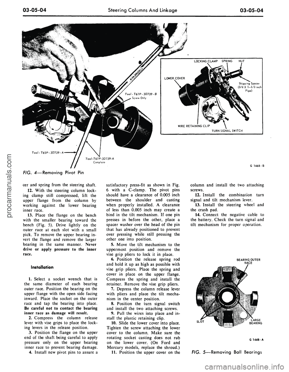
Install tool T67P-3D739-B as
shown in Fig. 4. Thread the bolt in-
ward finger tight until it bottoms, then
back it out one full turn. Make sure
that the handle is centered over the
pivot pin to prevent bolt breakage.
Hold the 3/8 inch bolt head station-
ary, then tighten the nut to extract the
pin. Repeat this operation on the op-
posite pin.
11.
Remove the nut, shipping spa-
UPPER
COVER
J
G 1498-B
FIG. 3—Typical Steering Column—Disassembledprocarmanuals.com
Page 117 of 413
03-05-04
Steering Columns And Linkage
03-05-04
Shipping Spacer
(3/4 X 1-1/3 inch
Pipe)
TURN SIGNAL SWITCH
Too/-T65P-3D739-A
G 1468-3
FIG. 4—Removing Pivot
Pin
cer and spring from the steering shaft.
12.
With
the
steering column lock-
ing clamp still compressed, lift
the
upper flange from
the
column
by
working against
the
lower bearing
inner race.
13.
Place
the
flange
on the
bench
with
the
smaller bearing toward
the
bench (Fig.
5).
Drive lightly
on the
outer race
at
each slot with
a
small
pick.
To
remove the upper bearing in-
vert
the
flange
and
remove
the
larger
bearing
in the
same manner. Never
drive
or
apply pressure
to the
inner
race.
Installation
1.
Select
a
socket wrench that
is
the same diameter
of
each bearing
outer race. Position the bearing on the
upper flange with the open side facing
inward. Place
the
socket
on the
outer
race
and tap the
bearing into place.
Be careful not
to
contact
the
bearing
inner race
as
damage will result.
2.
Compress
the
column release
lever with vise grips
to
place the lock-
ing levers
in the
release position.
3.
Position
the
flange
on the
upper
end
of
the shaft being careful
to
apply
pressure only
on the
upper bearing
inner race
to
prevent bearing damage.
4.
Install new pivot pins
to
assure
a
satisfactory press-fit
as
shown
in Fig.
6 with
a
C-clamp.
The
pivot pins
should have
a
clearance
of
0.005 inch
between
the
shoulder
and
casting
when properly installed.
A
clearance
of less than 0.005 inch may create
a
bind
in the
tilt mechanism.
If
one pin
presses
in
before
the
other, place
a
spacer washer over the head
of
the pin
that has already positioned
to
prevent
over pressing while still pressing
the
other one into position.
5.
Move
the
tilt mechanism
to the
uppermost position
and
remove
the
vise grip pliers
to
lock
it in
place.
6. Position
the
release spring
rod
and hold
it
up
as
high
as
possible with
vise grip pliers. Place
the
spring
and
cover
in
place
on the
upper flange.
Compress
the
spring
and
install
the
retainer. Remove the vise grip pliers.
7.
Depress
the
column release lever
with pliers
and
place
the
tilt mecha-
nism
in the
center position.
8. Position
the
turn signal switch
and install
the
two attaching screws.
9. Pull
the
wires into place and
in-
stall
the
plastic retaining clip.
10.
Slide the lower cover into place.
Tighten
the
screw attaching the lower
cover
to the
column. Make sure
the
rotating socket casting does
not rub
on
the
lower cover.
(On
Ford
and
Mercury models, replace
the
shroud.)
11.
Position the upper cover
on the
column
and
install
the
two attaching
screws.
12.
Install
the
combination turn
signal
and
tilt mechanism lever.
13.
Install
the
steering v/heel
and
the crash pad.
14.
Connect
the
negative cable
to
the battery. Check the turn signal and
tilt mechanism
for
proper operation.
BEARING OUTER
RACE
SLOT
G 1448-A
FIG. 5—Removing Ball Bearingsprocarmanuals.com
Page 120 of 413
03-05-07
Steering Columns And Linkage
03-05-07
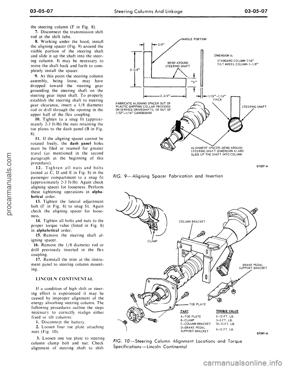
the steering column
(F in Fig. 8).
7.
Disconnect
the
transmission shift
rod
at the
shift tube.
8. Working under
the
hood, install
the aligning spacer (Fig.
9)
around
the
visible portion
of the
steering shaft
and slide
it up the
shaft into
the
steer-
ing column.
It may be
necessary
to
move
the
shaft back
and
forth
to
com-
pletely install
the
spacer.
9.
At
this point
the
steering column
assembly, being loose,
may
have
dropped toward
the
steering gear
grounding
the
steering shaft
on the
steering gear input shaft.
To
properly
establish
the
steering shaft
to
steering
gear clearance, insert
a 1/8
diameter
rod
or
drill through
the
opening
in the
upper half
of the
flex coupling.
10.
Tighten
to a
snug
fit
(approxi-
mately
2-3
ft-lb)
the
nuts retaining
the
toe plates
to the
dash panel
(B in Fig.
8).
11.
If the
aligning spacer cannot
be
rotated freely,
the
dash panel holes
must
be
filed
or
reamed
for
greater
travel
(as
mentioned
in the
second
paragraph
at the
beginning
of
this
procedure).
12.
Tighten
all
nuts
and
bolts
(noted
as C, D and E in
Fig.
8) in the
passenger compartment
to a
snug
fit
(approximately 2-3 ft-lb). Again check
aligning spacer
for
looseness. Perform
these tightening operations
in
alpha-
betical order.
13.
Tighten
the
lateral adjustment
bolt
(F in Fig. 8) to
snug
fit.
Again
check
the
aligning spacer
for
loose-
ness.
14.
Tighten
all
bolts and nuts
to the
proper torque value (listed
in Fig. 8)
in alphabetical order.
15.
Remove
the
steering shaft
al-
igning spacer.
16.
Remove
the 1/8
diameter
rod or
drill previously inserted
in the
flex
coupling.
17.
Reinstall
the
trim
at the
instru-
ment panel
to
steering column mount-
ing.
LINCOLN CONTINENTAL
If
a
condition
of
high shift
or
steer-
ing effort
is
experienced
it may be
caused
by
improper alignment
of the
energy absorbing steering column.
The
following procedures outline
the
steps
necessary
to
correctly realign either
fixed
or
tilt columns:
1.
Disconnect
the
battery.
2.
Loosen four
toe
plate attaching
nuts (Fig.
10).
3.
Loosen
one toe
plate
to
steering
column clamp bolt
and nut.
Check
alignment
of
steering shaft
to
shift
-HANDLE PORTION
2-3/4"
-*- 3/4"
BEND AROUND
STEERING SHAFT
DIMENSION
A:
STANDARD COLUMN 7/16"
TILT WHEEL COLUMN
1-1/8"
•2-3/4
FABRICATE ALIGNING SPACER OUT OF
PLASTIC SHIPPING COLLAR PROVIDED
ON SERVICE DRIVESHAFTS, OR OUT
OF
1/32"—1/16" CARDBOARD
STEERING SHAFT
ALIGNMENT SPACER-BEND AROUND
STEERING SHAFT (DIMENSION
A)
AND
SLIDE UP THE SHAFT INTO COLUMN
G1537-A
FIG. 9—Aligning Spacer Fabrication
and
Insertion
BRAKE PEDAL
SUPPORT BRACKET
PART
A-TOE PLATE
B-CLAMP
C-C0LUMN BRACKET
D-BRAKE PEDAL
SUPPORT BRACKET
TORQUE VALUE
8-12 FT. LB.
3-5 FT. LB.
10-15
FT.
LB.
8-12 FT. LB.
G1541-A
FIG. 10—Steering Column Alignment Locations
and
Torque
Specifications—Lincoln Continentalprocarmanuals.com
Page 121 of 413
03-05-08
Steering Columns And Linkage
03-05-08
tube.
In some instances the column
will shift into proper alignment when
the toe plate attaching nuts are loos-
ened. (Alignment is acceptable if a
.010 inch feeler blade can be passed
freely, completely around the area be-
tween the outer diameter of the steer-
ing shaft and the shift tube.) if the
misalignment condition can be attrib-
uted to this area, file or ream the dash
panel holes for greater clearance. If
the alignment is maintained after the
toe plate nuts and toe plate to column
clamp bolt and nut are torqued to the
8-12 ft-lb specification, no further ad-
justment is necessary.
4.
Remove instrument panel lower
trim panel. Vehicles equipped with a
combination radio stereo tape player
will require removal of the radio and
tape player assembly in order to gain
access to the upper R.H. steering col-
umn support bracket bolt.
5.
Loosen the seven bolts at the
steering column support bracket and
brake pedal support bracket.
6. Install a 3/16 inch diameter rod
spacer in the flex coupling to assure
proper clearance between upper and
lower steering shaft.
7.
Raise the vehicle, remove the
transmission splash shield, and visual-
ly align the column to center the
steering shaft in the column. Tighten
two toe plate attaching nuts sufficient-
ly to hold the column alignment (two
persons may be required for this oper-
ation).
8. Lower the vehicle.
9. Check the clearance between the
steering column support bracket and
the instrument panel bracket. It may
be necessary to add shims (Part Num-
ber MK-3054-A .060 inch thick, or
C3AZ-3054-A, .113 inch thick) be-
tween the support bracket and the in-
strument panel bracket to prevent
movement of the column when the
support bracket bolts are tightened.
10.
Loosen the two toe plate at-
taching nuts previously tightened. Re-
check steering column alignment. In
some instances it may be necessary to
enlarge the holes in the dash panel in
order to obtain proper column align-
ment.
11.
With the column properly al-
igned, torque the four toe plate at-
taching nuts to 4-9 ft-lbs.
12.
Torque the toe plate to steering
column clamp bolt to 3-5 ft-lbs.
13.
Recheck steering shaft to shift
tube alignment. A 0.10 inch feeler
blade should pass freely, completely
around the area between the outer di-
ameter of the steering shaft and shift-
er tube.
14.
Raise the vehicle.
15.
Adjust transmission shift link-
age.
16.
Install transmission splash
shield.
17.
Lower the vehicle.
18.
Install the radio stereo tape
player if so equipped.
19.
Install instrument panel lower
trim panel.
20.
Connect the battery.
REMOVAL AND INSTALLATION
STEERING COLUMN
FORD, MERCURY, METEOR
Removal
1.
Disconnect the battery cable
from the negative post.
2.
Disconnect the turn signal switch
wires at the connector.
3.
Disconnect the neutral start
switch and back-up light switch wires
from the switches.
4.
Disconnect the transmission con-
trol rod(s) from the lever(s) at the
lower end of the column.
5.
Remove the bolt that secures the
flex coupling to the steering gear.
6. Remove the nuts that secure the
column retainer and seal at the toe
plate (Fig. 11).
7.
Ford, Meteor: Remove the two
screws that secure the lower trim
shroud to the upper trim shroud. Re-
move the two shrouds.
Mercury: Remove the two screws
that secure the lower trim shroud to
the upper trim shroud. Remove the
top shroud Disconnect the ignition
switch light bulb. Remove the ignition
and light switch bezels and spring clip
and remove the lower shroud. Discon-
nect the light switch electrical connec-
tor block.
8. Remove the two screws that se-
cure the intermediate bracket to the
column lower bracket.
9. While supporting the steering
column, remove the two nuts that se-
cure the column lower bracket to the
instrument panel. Remove the brack-
ets.
10.
Lift the steering column and
wheel from the vehicle.
Installation
1.
Position the steering column in
the vehicle. Index the block tooth on
the steering gear shaft with the corre-
sponding slot on the flex coupling. In-
stall and tighten the flex coupling-
to-steering gear attaching bolt.
2.
Place the column upper bracket
and column lower bracket in position
on the column and install but do not
tighten the four attaching nuts.
3.
Install and tighten the two nuts
that secure the column lower bracket
to the instrument panel. Make certain
the column is properly positioned rela-
tive to the flex coupling input shaft
connection.
4.
Install and tighten the screws
that secure the intermediate bracket to
the column lower bracket.
5.
Tighten the four attaching nuts
at the upper and lower brackets and
the two nuts at the upper bracket to
instrument panel. The dial pointer (if
so equipped) should be adjusted to
coincide with the selector lever.
6. Install and tighten the nuts and
bolts that secure the column retainer
and seal at the toe plate. Make sure
the steering shaft is centered in the
column before tightening the nuts.
7.
Ford, Meteor: Install and tighten
the two screws that secure the lower
trim shroud to the upper trim shroud.
Mercury: Connect the light switch
harness block. Install the ignition and
light switch bezels. Connect the igni-
tion switch light bulb. Install the top
shroud and the two screws that secure
the lower trim shroud to the upper
shroud.
8. Connect the transmission control
rod(s) to the lever(s) at the lower end
of the column.
9. Connect the neutral start switch
and back-up light switch to their re-
spective terminals.
10.
Connect the turn signal switch
wires.
11.
Connect the negative battery
cable to the battery.
12.
Check the operation of the
steering tilt mechanism if so equipped
and the switches.procarmanuals.com