FORD MUSTANG 2003 Workshop Manual
MUSTANG 2003
FORD
FORD
https://www.carmanualsonline.info/img/11/56942/w960_56942-0.png
FORD MUSTANG 2003 Workshop Manual
Page 911 of 4378
GENERAL PROCEDURES
Valve Stem to Valve Guide Clearance
NOTE:
Valve stem diameter must be within specifications before checking valve stem to valve guide
clearance.
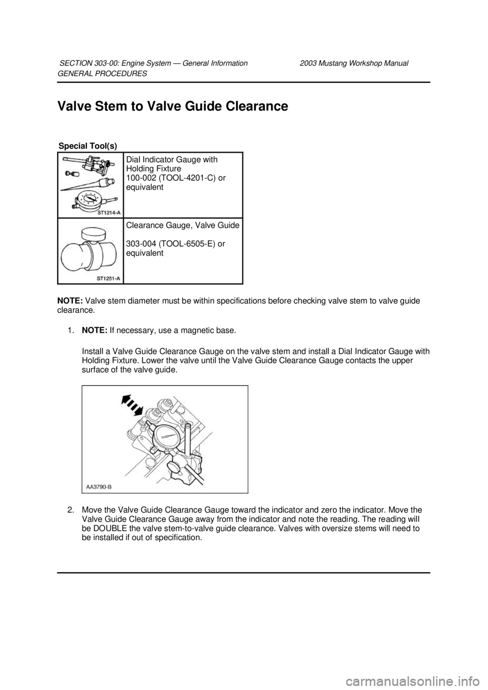
1. NOTE: If necessary, use a magnetic base.
Install a Valve Guide Clearance Gauge on the valve stem and install a Dial Indicator Gauge with
Holding Fixture. Lower the valve until the Valve Guide Clearance Gauge contacts the upper
surface of the valve guide.
2. Move the Valve Guide Clearance Gauge toward the indicator and zero the indicator. Move the Valve Guide Clearance Gauge away from the indicator and note the reading. The reading will
be DOUBLE the valve stem- to-valve guide clearance. Valves with oversize stems will need to
be installed if out of specification.
SECTION 303-
00: Engine System — General Information 2003 Mustang Workshop Manual Special Tool(s)
Dial Indicator Gauge with
Holding Fixture
100-
002 (TOOL- 4201-C) or
equivalent Clearance Gauge, Valve Guide
303-
004 (TOOL- 6505-E) or
equivalent �K�l�j . 1 �b�a
22003 Mustang Workshop Manual
17. 11. 2011file:///C:/Ford/2000 - 2004/tsocache/SHEF_4464/S3B~us~en~ ...
Page 913 of 4378
GENERAL PROCEDURES
Valve —
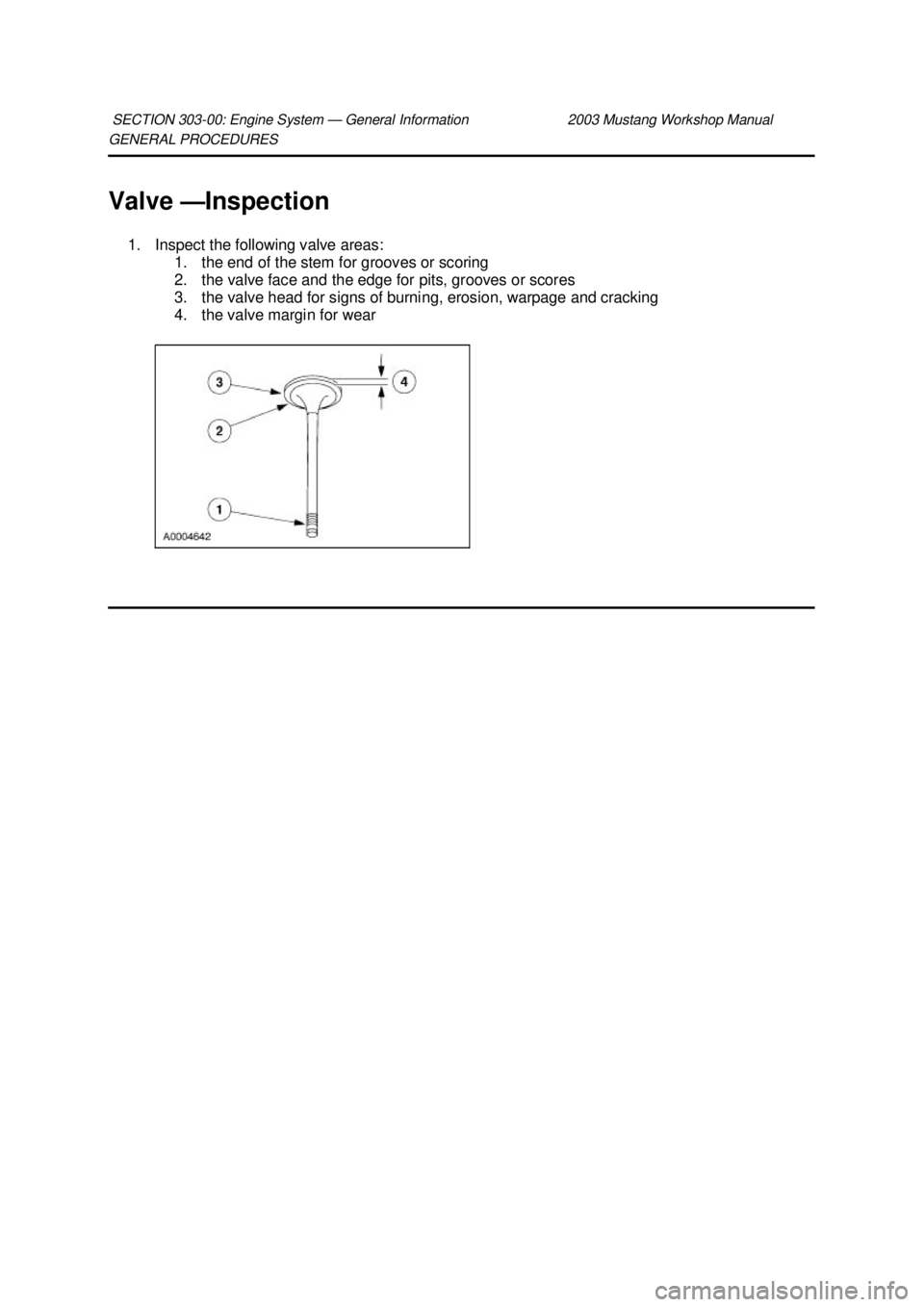
Inspection
1. Inspect the following valve areas: 1. the end of the stem for grooves or scoring
2. the valve face and the edge for pits, grooves or scores
3. the valve head for signs of burning, erosion, warpage and cracking
4. the valve margin for wear
SECTION 303-
00: Engine System — General Information 2003 Mustang Workshop Manual �K�l�j . 1 �b�a
12003 Mustang Workshop Manual
17. 11. 2011file:///C:/Ford/2000 - 2004/tsocache/SHEF_4464/S3B~us~en~ ...
Page 914 of 4378
GENERAL PROCEDURES
Valve —
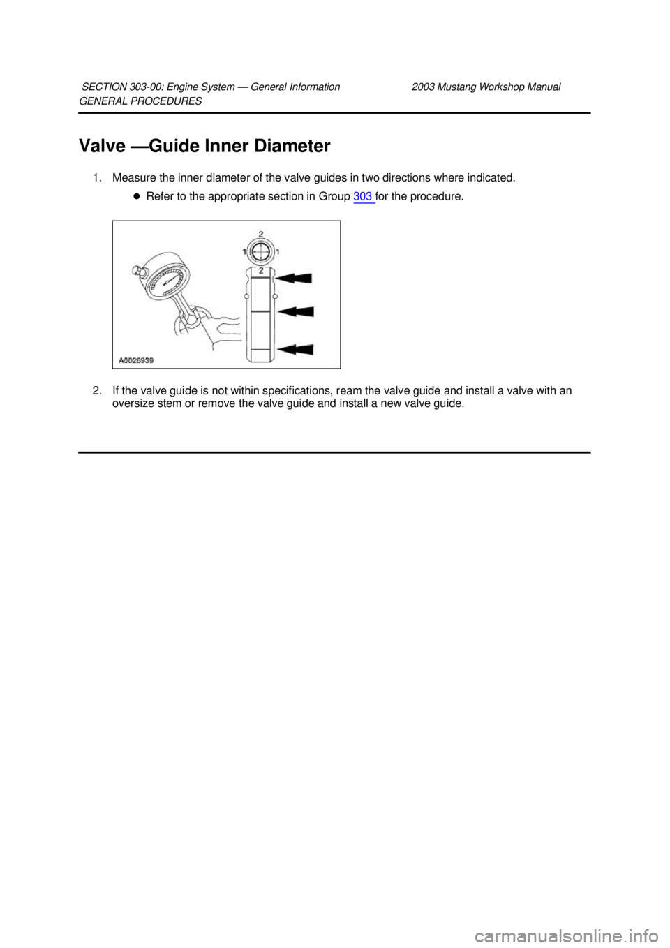
Guide Inner Diameter
1. Measure the inner diameter of the valve guides in two directions where indicated. �zRefer to the appropriate section in Group 303 for the procedure.
2. If the valve guide is not within specifications, ream the valve guide and install a valve with an oversize stem or remove the valve guide and install a new valve guide.
SECTION 303-
00: Engine System — General Information 2003 Mustang Workshop Manual �K�l�j . 1 �b�a
12003 Mustang Workshop Manual
17. 11. 2011file:///C:/Ford/2000 - 2004/tsocache/SHEF_4464/S3B~us~en~ ...
Page 915 of 4378
GENERAL PROCEDURES
Valve —
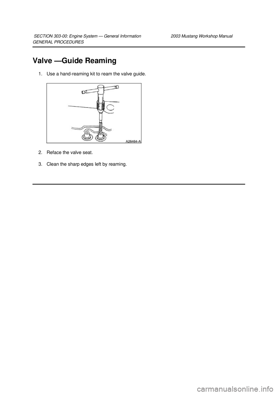
Guide Reaming
1. Use a hand- reaming kit to ream the valve guide.
2. Reface the valve seat.
3. Clean the sharp edges left by reaming.
SECTION 303-
00: Engine System — General Information 2003 Mustang Workshop Manual �K�l�j . 1 �b�a
12003 Mustang Workshop Manual
17. 11. 2011file:///C:/Ford/2000 - 2004/tsocache/SHEF_4464/S3B~us~en~ ...
Page 916 of 4378
GENERAL PROCEDURES
Valve —
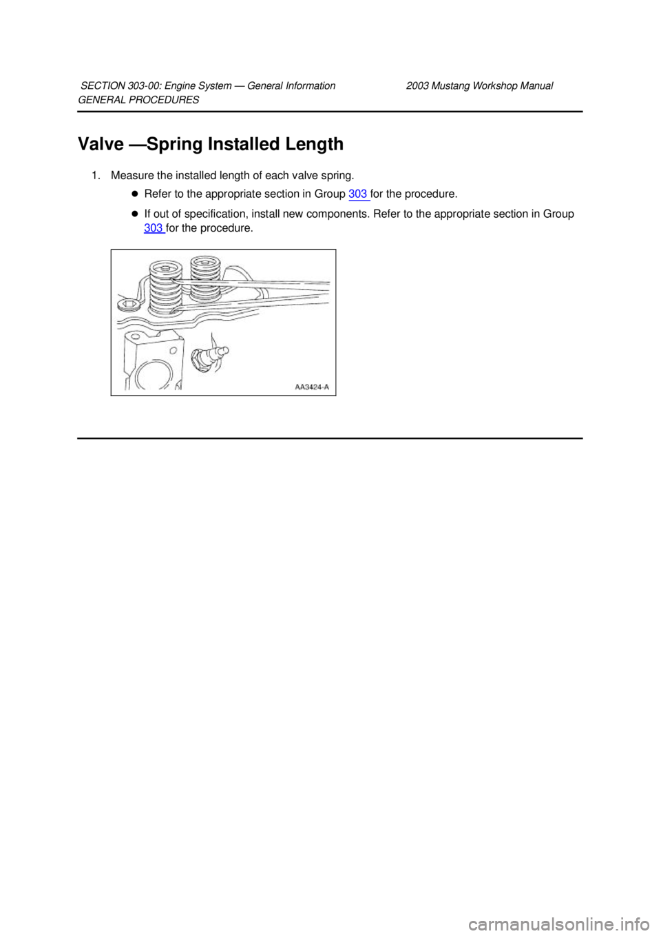
Spring Installed Length
1. Measure the installed length of each valve spring. �zRefer to the appropriate section in Group 303 for the procedure.
�z If out of specification, install new components. Refer to the appropriate section in Group
303 for the procedure.
SECTION 303-
00: Engine System — General Information 2003 Mustang Workshop Manual �K�l�j . 1 �b�a
12003 Mustang Workshop Manual
17. 11. 2011file:///C:/Ford/2000 - 2004/tsocache/SHEF_4464/S3B~us~en~ ...
Page 917 of 4378
GENERAL PROCEDURES
Valve —
Spring Free Length
1. Measure the free length of each valve spring. �zRefer to the appropriate section in Group 303 for the procedure.
�z If out of specification, install new components as necessary. Refer to the appropriate
section in Group 303 for the procedure.
SECTION 303-
00: Engine System — General Information 2003 Mustang Workshop Manual �K�l�j . 1 �b�a
12003 Mustang Workshop Manual
17. 11. 2011file:///C:/Ford/2000 - 2004/tsocache/SHEF_4464/S3B~us~en~ ...
Page 918 of 4378
GENERAL PROCEDURES
Valve —
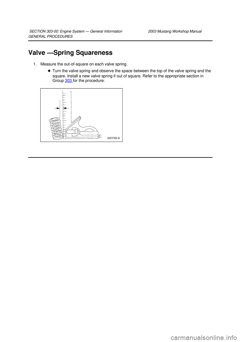
Spring Squareness
1. Measure the out-of- square on each valve spring.
�z Turn the valve spring and observe the space between the top of the valve spring and the
square. Install a new valve spring if out of square. Refer to the appropriate section in
Group 303 for the procedure.
SECTION 303-
00: Engine System — General Information 2003 Mustang Workshop Manual �K�l�j . 1 �b�a
12003 Mustang Workshop Manual
17. 11. 2011file:///C:/Ford/2000 - 2004/tsocache/SHEF_4464/S3B~us~en~ ...
Page 919 of 4378
GENERAL PROCEDURES
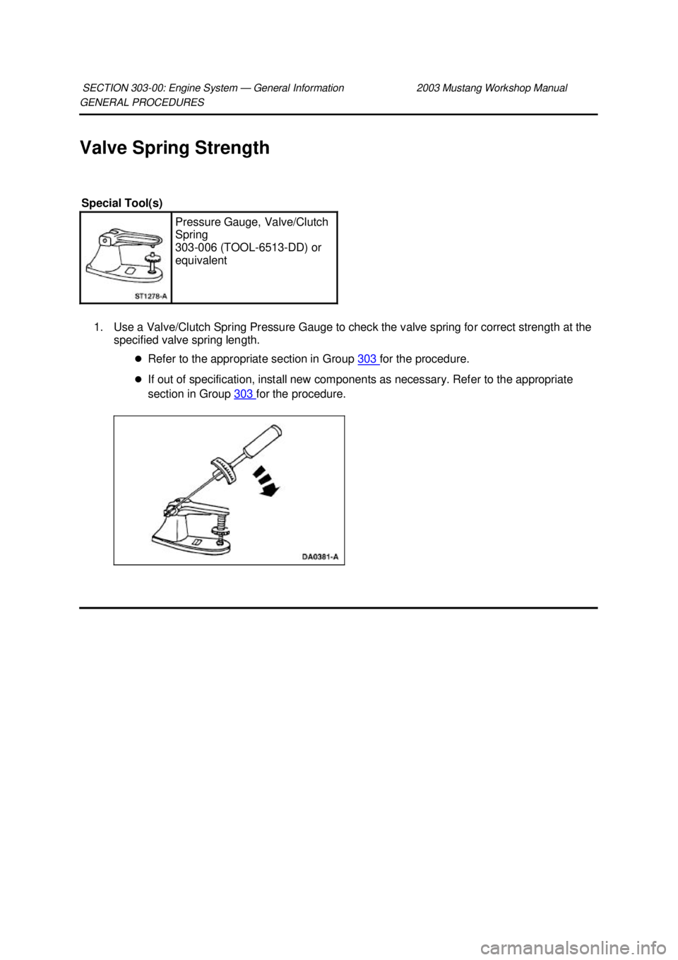
Valve Spring Strength
1. Use a Valve/Clutch Spring Pressure Gauge to check the valve spring for correct strength at the specified valve spring length.
�zRefer to the appropriate section in Group 303 for the procedure.
�z If out of specification, install new components as necessary. Refer to the appropriate
section in Group 303 for the procedure.
SECTION 303-
00: Engine System — General Information 2003 Mustang Workshop Manual Special Tool(s)
Pressure Gauge, Valve/Clutch
Spring
303-
006 (TOOL- 6513-DD) or
equivalent �K�l�j . 1 �b�a
22003 Mustang Workshop Manual
17. 11. 2011file:///C:/Ford/2000 - 2004/tsocache/SHEF_4464/S3B~us~en~ ...
Page 921 of 4378
GENERAL PROCEDURES
Valve —
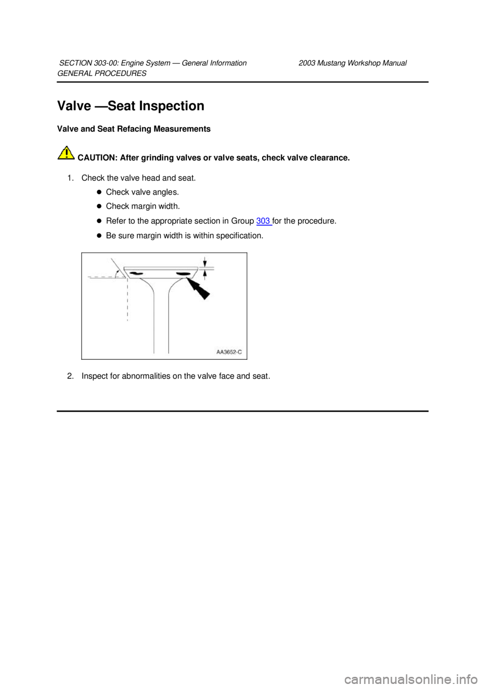
Seat Inspection
Valve and Seat Refacing Measurements
CAUTION: After grinding valves or valve seats, check valve clearance.
1. Check the valve head and seat. �zCheck valve angles.
�z Check margin width.
�z Refer to the appropriate section in Group 303 for the procedure.
�z Be sure margin width is within specification.
2. Inspect for abnormalities on the valve face and seat.
SECTION 303-
00: Engine System — General Information 2003 Mustang Workshop Manual �K�l�j . 1 �b�a
12003 Mustang Workshop Manual
17. 11. 2011file:///C:/Ford/2000 - 2004/tsocache/SHEF_4464/S3B~us~en~ ...
Page 922 of 4378
GENERAL PROCEDURES
Valve —
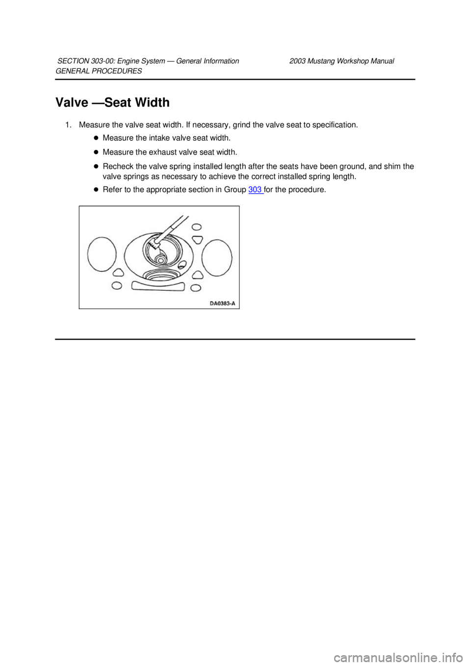
Seat Width
1. Measure the valve seat width. If necessary, grind the valve seat to specification. �zMeasure the intake valve seat width.
�z Measure the exhaust valve seat width.
�z Recheck the valve spring installed length after the seats have been ground, and shim the
valve springs as necessary to achieve the correct installed spring length.
�z Refer to the appropriate section in Group 303 for the procedure.
SECTION 303-
00: Engine System — General Information 2003 Mustang Workshop Manual �K�l�j . 1 �b�a
12003 Mustang Workshop Manual
17. 11. 2011file:///C:/Ford/2000 - 2004/tsocache/SHEF_4464/S3B~us~en~ ...

