FORD TRANSIT 2006 7.G Body And Equipment Mounting Section Manual
Manufacturer: FORD, Model Year: 2006,
Model line: TRANSIT,
Model: FORD TRANSIT 2006 7.G
Pages: 234, PDF Size: 33.19 MB
FORD TRANSIT 2006 7.G Body And Equipment Mounting Section Manual
TRANSIT 2006 7.G
FORD
FORD
https://www.carmanualsonline.info/img/11/5471/w960_5471-0.png
FORD TRANSIT 2006 7.G Body And Equipment Mounting Section Manual
Trending: jacking, flat tire, brake light, change key battery, buttons, fuel type, spare wheel
Page 101 of 234
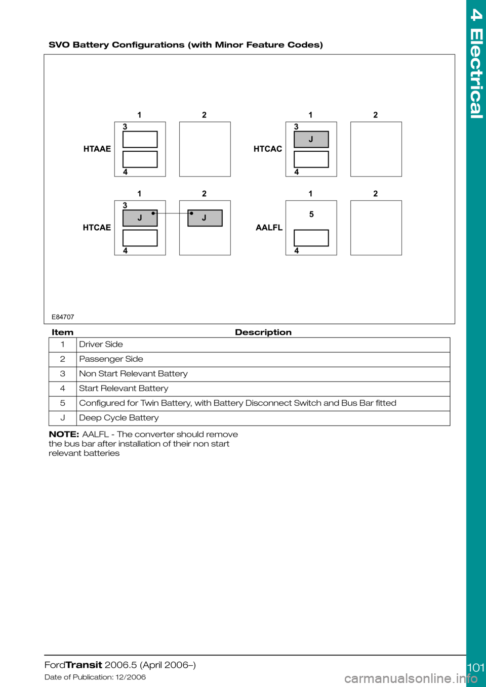
SVO Battery Configurations (with Minor Feature Codes)
DescriptionItem
Driver Side1
Passenger Side2
Non Start Relevant Battery3
Start Relevant Battery4
Configured for Twin Battery, with Battery Disconnect Switch and Bus Bar fitted5
Deep Cycle BatteryJ
NOTE: AALFL - The converter should remove
the bus bar after installation of their non start
relevant batteries
FordTransit 2006.5 (April 2006–)
Date of Publication: 12/2006
4 Electrical
1013143142231414522JJJE84707
Page 102 of 234
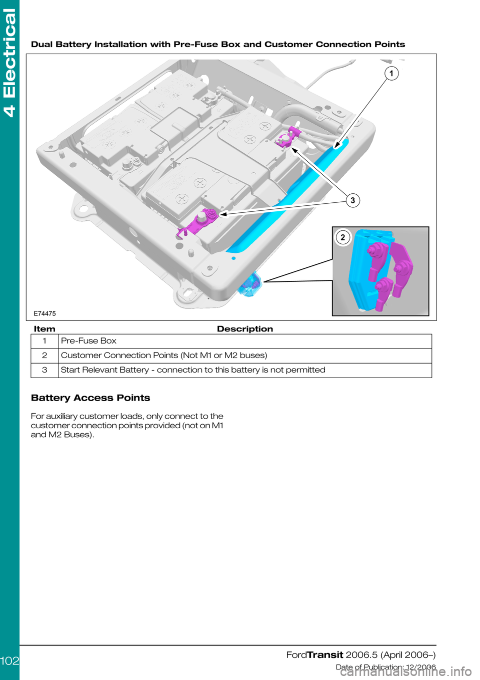
Dual Battery Installation with Pre-Fuse Box and Customer Connection Points
DescriptionItem
Pre-Fuse Box1
Customer Connection Points (Not M1 or M2 buses)2
Start Relevant Battery - connection to this battery is not permitted3
Battery Access Points
For auxiliary customer loads, only connect to the
customer connection points provided (not on M1
and M2 Buses).
FordTransit 2006.5 (April 2006–)
Date of Publication: 12/2006
4 Electrical
102E74475132
Page 103 of 234
4.4.2 Generator and Alternator
Torque Curve of Alternator
Diagram E75871 shows the torque in Nm which
is required to drive the alternator. The vertical
axis (A) shows the torque [Nm] and the horizontal
axis (B) shows the alternators revolutions per
minute [1/min].
NOTE: For equivalent engine revs per minute
(RPM), the alternators revolutions, axis (B) should
be divided by the following factors: 2.66 for diesel
(2.2L and 2.4L), 2.4 for Gasoline (2.3L).
NOTE: These alternator curves do not show
spare output capacity as this would be
dependant on original vehicle features and
options
FordTransit 2006.5 (April 2006–)
Date of Publication: 12/2006
4 Electrical
1030246810121402000400060008000100001200014000160001800020000ABE75871
Page 104 of 234
Current in relation to revolutions per minute
Diagram E75872 shows the current (A) in relation
to alternators revolutions (B) per minute [1/min].
This preliminary Bosch performance curve (1)
arose at a temperature of 25°C and a voltage of
13,5V.
FordTransit 2006.5 (April 2006–)
Date of Publication: 12/2006
4 Electrical
1040204060801001201401601800200040006000800010000120001400016000A1BE75872
Page 105 of 234
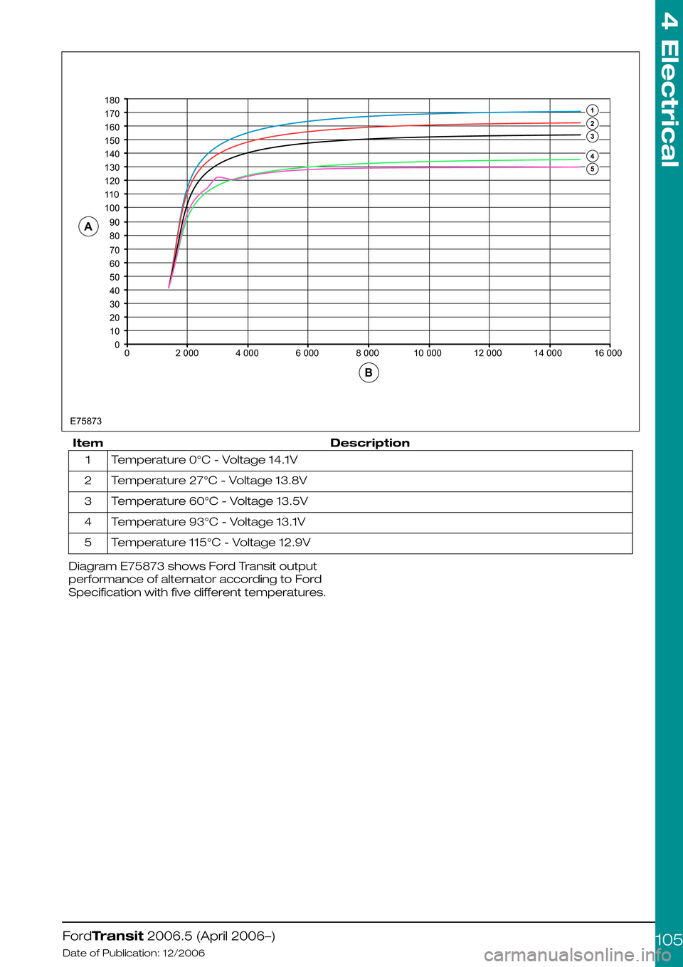
DescriptionItem
Temperature 0°C - Voltage 14.1V1
Temperature 27°C - Voltage 13.8V2
Temperature 60°C - Voltage 13.5V3
Temperature 93°C - Voltage 13.1V4
Temperature 115°C - Voltage 12.9V5
Diagram E75873 shows Ford Transit output
performance of alternator according to Ford
Specification with five different temperatures.
FordTransit 2006.5 (April 2006–)
Date of Publication: 12/2006
4 Electrical
105001020304050607080901001101201301401501601701802000E7587340006000800010000120001400016000AB54321
Page 106 of 234
4.5 Climate Control System
WARNING: Do not use propylene
glycol based coolant
•Never secure hoses or tubes to the
transmission fill or dip stick or to any fuel
system or brake component
•Do not route heater or refrigerant lines near or
directly over any exhaust system component,
including the exhaust manifolds.
•Avoid routing of hoses in the wheelhouse or
stone kick-up arch. However, if routing is
required in these areas, shield against stone
pecking as appropriate.
•Do not route hoses near sharp edges. Utilize
guards to protect against cutting or chafing.
FordTransit 2006.5 (April 2006–)
Date of Publication: 12/2006
4 Electrical
106
Page 107 of 234
4.6 Instrument Cluster
WARNING: Do not tamper with, cut
into or connect to any of the
CAN-Bus interface wiring or
connectors.
The Transit has a Hybrid electronic Cluster (HEC).
Most of the functions are managed over the
CAN-Bus interface (pins 3-8)
FordTransit 2006.5 (April 2006–)
Date of Publication: 12/2006
4 Electrical
107
Page 108 of 234
4.7 Horn
A dual horn may be fitted to the vehicle in place
of the single horn.
Any other aftermarket horn (for example an air
horn) will need to be driven by a separate relay
energised by the horn circuit.
FordTransit 2006.5 (April 2006–)
Date of Publication: 12/2006
4 Electrical
108
Page 109 of 234
4.8 Tachograph
The factory-fit Tachograph option uses a
Siemens VDO system. It is recommended,
therefore, that any vehicle that requires a
tachograph is sent to an authorised Siemens
VDO Tachograph Service Centre for system
installation and calibration.
Details of all recommended Service Centers can
be found on Siemens web site. This site also
contains details of current regulations and
tachograph operation.
4.8.1 Legislation
WARNING: All tachographs require
the same wiring connections as this
is controlled by tachograph
legislation.
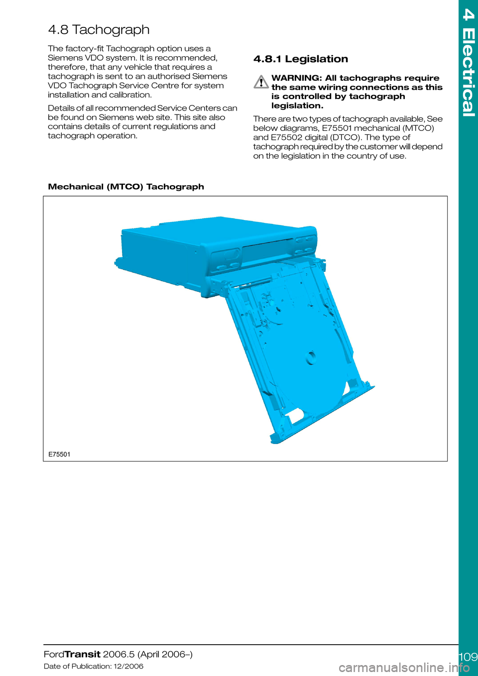
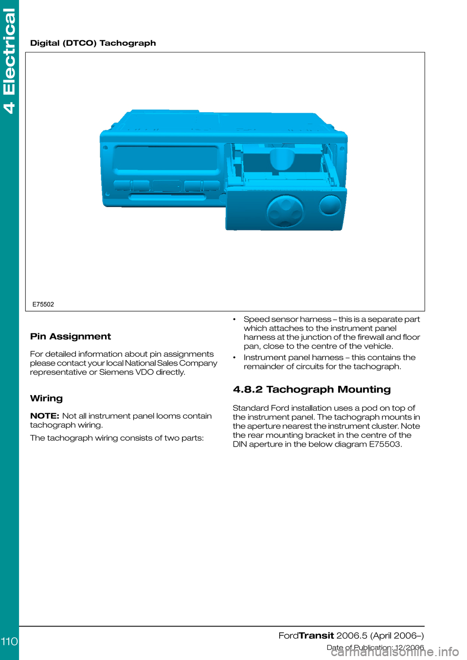
There are two types of tachograph available, See
below diagrams, E75501 mechanical (MTCO)
and E75502 digital (DTCO). The type of
tachograph required by the customer will depend
on the legislation in the country of use.
Mechanical (MTCO) Tachograph
FordTransit 2006.5 (April 2006–)
Date of Publication: 12/2006
4 Electrical
109E75501
Page 110 of 234
Digital (DTCO) Tachograph
Pin Assignment
For detailed information about pin assignments
please contact your local National Sales Company
representative or Siemens VDO directly.
Wiring
NOTE: Not all instrument panel looms contain
tachograph wiring.
The tachograph wiring consists of two parts:
•Speed sensor harness – this is a separate part
which attaches to the instrument panel
harness at the junction of the firewall and floor
pan, close to the centre of the vehicle.
•Instrument panel harness – this contains the
remainder of circuits for the tachograph.
4.8.2 Tachograph Mounting
Standard Ford installation uses a pod on top of
the instrument panel. The tachograph mounts in
the aperture nearest the instrument cluster. Note
the rear mounting bracket in the centre of the
DIN aperture in the below diagram E75503.
FordTransit 2006.5 (April 2006–)
Date of Publication: 12/2006
4 Electrical
110E75502
Trending: warning light, turn signal, instrument cluster, vehicle speed, seat adjustment, towing capacity, fuse box location
![FORD TRANSIT 2006 7.G Body And Equipment Mounting Section Manual 4.4.2 Generator and Alternator
Torque Curve of Alternator
Diagram E75871 shows the torque in Nm which
is required to drive the alternator. The vertical
axis (A) shows the torque [Nm] and the horizon FORD TRANSIT 2006 7.G Body And Equipment Mounting Section Manual 4.4.2 Generator and Alternator
Torque Curve of Alternator
Diagram E75871 shows the torque in Nm which
is required to drive the alternator. The vertical
axis (A) shows the torque [Nm] and the horizon](/img/11/5471/w960_5471-102.png)
![FORD TRANSIT 2006 7.G Body And Equipment Mounting Section Manual
Current in relation to revolutions per minute
Diagram E75872 shows the current (A) in relation
to alternators revolutions (B) per minute [1/min].
This preliminary Bosch performance curve (1)
arose a FORD TRANSIT 2006 7.G Body And Equipment Mounting Section Manual
Current in relation to revolutions per minute
Diagram E75872 shows the current (A) in relation
to alternators revolutions (B) per minute [1/min].
This preliminary Bosch performance curve (1)
arose a](/img/11/5471/w960_5471-103.png)
