brake GEELY MK 2008 Owner's Manual
[x] Cancel search | Manufacturer: GEELY, Model Year: 2008, Model line: MK, Model: GEELY MK 2008Pages: 416, PDF Size: 25.19 MB
Page 83 of 416

Transmission ControlManual Transmission Shift Mechanism4-610. Connect the control cables assembly.
(1) Connect the control cables to floor gear shift lever assembly.
Note:
Make sure the spring clips engage firmly.
(2) Connect the ends of the control cables to the floor gear shift
lever assembly, and then install the cotter pins.
Note:
When connecting the ends, the dents shall be made upwards.
The cotter pins are inserted in a direction as shown in the figure.
(3) Connect the ends of the gear shift cables to the floor gear shift
lever assembly.
11. Install the middle console body.
12. Install the parking brake cover.
13. Install the handle of the gear shift lever.
14. Install the cup-holder.
15. Install the lower cover in dashboard panel.
16. Install the upper cover in dashboard panel.Sawcat part -
Page 84 of 416

Transmission ControlAutomatic Transmission Shift Mechanism4-7Section 4 Automatic Transmission Shift MechanismComponent ViewConsole Panel Upper
Cover Assembly E Clip
Console Panel Lower
Cover Assembly
Cup Holder
Park Brake Cover Plate
E Clip
Console Assembly
Automatic Shifter Assembly121212 Shift Cable Key Retaining Cable E Clip
Specified Torque -
Page 87 of 416

4-108. Install the automatic shifter assembly
Install it in place in the reverse order of removal.
9. Check and adjust the shift lever position
(1) Check that the starter works only when the shift lever is in P position, but doesn't work in other positions.
(2) Move the shift lever, check whether the display of the gear range indicator is consistent with the actual gear
range.
(3) Check that the key can be pulled out in P position.
(4) Except the P position, the ignition key can not be turned to LOCK position with the shift lever in other
positions.
(5) Check that when shift release button is pressed down, the shift lever can be transferred to other positions
from the P position.
10. Adjustment
(1) When moving shift lever among the positions, make sure to
move the shift lever in a stable way, operate properly and the
positive display is correct.
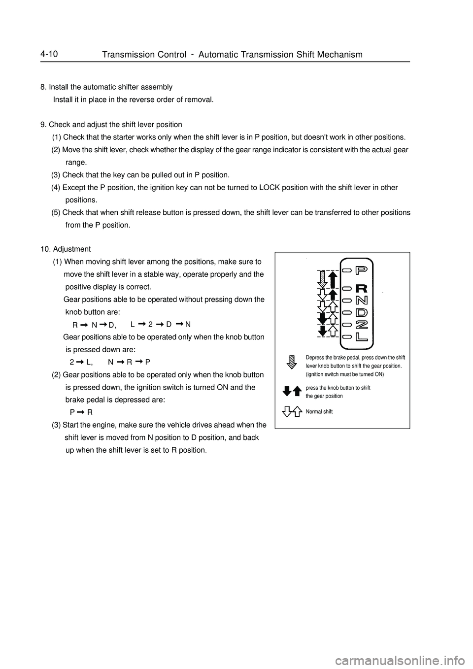
Gear positions able to be operated without pressing down the
knob button are:
R N D,L 2 D N
Gear positions able to be operated only when the knob button
is pressed down are:
2 L,N R P
(2) Gear positions able to be operated only when the knob button
is pressed down, the ignition switch is turned ON and the
brake pedal is depressed are:
P R
(3) Start the engine, make sure the vehicle drives ahead when the
shift lever is moved from N position to D position, and back
up when the shift lever is set to R position.Depress the brake pedal, press down the shift
lever knob button to shift the gear position.
(ignition switch must be turned ON)
press the knob button to shift
the gear position
Normal shiftTransmission ControlAutomatic Transmission Shift Mechanism -
Page 91 of 416

b. Tighten the lock nut.
Torque: 12N.m
c. Check the pedal's height after adjusting the pedal's free
travel.
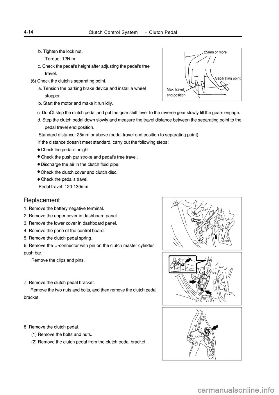
(6) Check the clutch's separating point.
a. Tension the parking brake device and install a wheel
stopper.
b. Start the motor and make it run idly. c. DonÕt step the clutch pedal,and put the gear shift lever to the reverse gear slowly till the gears engage.
d. Step the clutch pedal down slowly,and measure the travel distance between the separating point to the
pedal travel end position.
Standard distance: 25mm or above (pedal travel end position to separating point)
If the distance doesn't meet standard, carry out the following steps:
Check the pedal's height.
Check the push par stroke and pedal's free travel.
Discharge the air in the clutch fluid pipe.
Check the clutch cover and clutch disc.
Check the pedal's travel.
Pedal travel: 120-130mmReplacement1. Remove the battery negative terminal.
2. Remove the upper cover in dashboard panel.
3. Remove the lower cover in dashboard panel.
4. Remove the pane of the control board.
5. Remove the clutch pedal spring.
6. Remove the U-connector with pin on the clutch master cylinder
push bar.
Remove the clips and pins.
7. Remove the clutch pedal bracket.
Remove the two nuts and bolts, and then remove the clutch pedal
bracket.
8. Remove the clutch pedal.
(1) Remove the bolts and nuts.
(2) Remove the clutch pedal from the clutch pedal bracket.Clutch Control SystemClutch Pedal4-1425mm or more
Separating point
Max. travel
end position -
Page 94 of 416

Chapter 4 Propeller Shaft/DriveshaftSection 1 Propeller Shaft, Driveshaft and TransaxleI. Symptom Table The table below can help find the causes of the problem. The numbers indicate the priority of the causes of the
problem. Replace the parts if necessary.
Inspection Area
1. Wheel
2. Front wheel alignment
3. Rear wheel alignment
4. Front wheel hub bearing (worn)
5. Rear wheel hub bearing (worn)
6. Front shock absorber with coil spring
7. Steering linkage (loose or damaged)
8. Stabilizer bar
1. Wheel balance
2. Wheel hub bearing (worn)
3. Front shock absorber with coil spring
1. Outer joint (worn)
2. Inner joint (worn) Symptom
Deviation
Front wheel vibration
Noise (drive shaft)ReferenceII. On-board Inspection1. Check front wheel hub bearing
(1) Remove front wheel.
(2) Remove front brake caliper assembly.
(3) Remove front brake disc.
(4) Check the bearing backlash.
Set a dial indicator near the front wheel hub center to check
the backlash.
Maximum: 0.05mm
If the backlash exceeds the maximum value, replace the front
wheel hub bearing.
(5) Check the front wheel hub deviation
Using a dial indicator, check the deviation of the surface of the
wheel hub outside the hub bolt.
Maximum: 0.07mm
If the backlash exceeds the maximum value, replace the front
wheel hub subassembly.Propeller Shaft/DriveshaftPropeller Shaft, Driveshaft and Transaxle4-17 -
Page 95 of 416

(6) Install front brake disc.
(7) Install front brake caliper assembly
(8) Install font wheel.
Torque: 103N.m
2. Check back wheel hub bearing
(1) Remove rear wheel.
(2) Remove rear brake drum subassembly.
(3) Check bearing backlash.
Set a dial indicator near the rear wheel hub center to check the
backlash.
Maximum: 0.05mm
If the backlash exceeds the maximum value, replace the rear
wheel hub and bearing assembly.
(4) Check rear wheel hub deviation
Using a dial indicator, check the deviation of the surface of
the rear wheel hub inside the hub bolt.
Maximum: 0.07mm
If the backlash exceeds the maximum value, replace the rear
wheel hub and bearing assembly.
(5) Install rear brake subassembly
(6) Install rear wheel
Torque: 103N.mPropeller Shaft/DriveshaftPropeller Shaft, Driveshaft and Transaxle4-18 -
Page 96 of 416

Section 2 Front DriveshaftComponent Viewsnap ring
snap ring
set nutPropeller Shaft/DriveshaftFront Driveshaft4-19right constant velocity drive
shaft assembly
right constant velocity drive
shaft assembly
Tie rod left end assembly
cotter pin
left lower swing arm collar gasket collar
gasket with ABS LF vehicle speed sensor
brake hose
front stabilizer bar
cotter pin
specified torqueN.
m :
Non-reusable parts -
Page 98 of 416

Overhaul1. Drain manual transmission oil (M/T transmission)
Torque: 39N.m
2. Drain automatic transmission oil (A/T transmission)
Torque: 25N.m
3. Remove front wheel
4. Remove engine bottom left shield (M/T transaxle)
5. Remove engine bottom right shield (M/T transaxle)
6. Remove engine bottom shield assembly (A/T transaxle)
7. Remove front wheel hub left bolt
(1) Using a hammer and a drive shaft nut chisel, unstake the
staked part of the left wheel hub nut.
(2) While applying the brake pedal, remove the left wheel hub
nut.
Notice: the staked part of the nut should be fully unstaked,
otherwise it may damage the thread of the drive shaft.
8. Remove left front vehicle speed sensor (with ABS)
(1) Remove the bolt and clip, remove vehicle speed sensor and
brake hose from left front shock absorber assembly.
(2) Remove the bolt, separate the left front vehicle speed sensor
from steering knuckle.
9. Remove front stabilizer bar
(1) Use a 10mm wrench to hold the bolt, remove the nut
(2) Remove two collars, No.1 and No.2 gaskets, remove front
stabilizer barPropeller Shaft/DriveshaftFront Driveshaft4-21 -
Page 106 of 416

Propeller Shaft/DriveshaftFront Driveshaft4-29 (2) Install the new cotter pins.
Notice:
If the pin holes are not aligned, further tighten the nut by 60°.
43. Install front stabilizer bar
(1) As shown in the illustration, install the stabilizer bar with two
No.1 collars and two gaskets and nuts.
Notice:
Make sure the gaskets and collars are correctly installed.
(2) Tighten the nut with a 10mm wrench.
Torque: 18N.m
44. Install left front vehicle speed sensor (with ABS)
(1) Install the left front vehicle speed sensor and brake hose on the
front shock absorber with bolts and clps.
Torque: 29N.m
(2) Install the vehicle speed sensor on the steering knuckle with
bolts.
Torque: 8.0N.m
Notice:
Be careful not to damage the wheel speed sensor.
Keep the vehicle speed sensor clean.
When installing the sensor,do not twist the sensor wire harness.
45. Install left steering knuckle wheel hub nut
(1) Install new left steering knuckle hub nuts
Torque: 216N.m
(2) Using a chisel and hammer, stake the hub locking nut.
46. Install engine bottom left shield
47. Install engine bottom right shield
48. Install engine bottom shield assembly
49. Install front wheel
Torque: 103 N.m
50. Add oil into manual transmission
51. Check and adjust the manual transmission fluid
52. Refill automatic transmission fluid
53. Check and adjust the automatic transmission fluid
54. Check and adjust front wheel alignment
55. Check ABS vehicle speed signal (with ABS) -
Page 107 of 416

Section 3 Front Wheel HubComponent ViewLeft Constant Velocity
Drive Shaft Assembly
Left Brake Caliper Assembly
Retainer
Dual Ball Bearing
Left Steering Knuckle
Front Axle Hub Front Axle Hub NutBrake DiscPropeller Shaft/DriveshaftFront Wheel Hub4-30With ABS
Left Front Vehicle
Speed Sensor
Left Tie Rod End Subassembly
Brake Hose
Left Front Axle Assembly
No. 1 Cushion Collar
Cotter Pin
Cushion
ClipFront Stabilizer
Left No.1 Front Lower
Suspension Arm
SubassemblyLeft Front Axle Hub Nut
Left Front Brake Disc Dust Cover
specified torqueN.
m :No. 1 Cushion Collar - Non-reusable parts -