GREAT WALL FLORID 2008 Repair Manual
FLORID 2008
GREAT WALL
GREAT WALL
https://www.carmanualsonline.info/img/59/57164/w960_57164-0.png
GREAT WALL FLORID 2008 Repair Manual
Trending: wiper fluid, load capacity, ABS, washer fluid, battery location, alternator, diagnostic menu
Page 61 of 281
Downloaded from www.Manualslib.com manuals search engine GWFLORID Maintenance Manual54
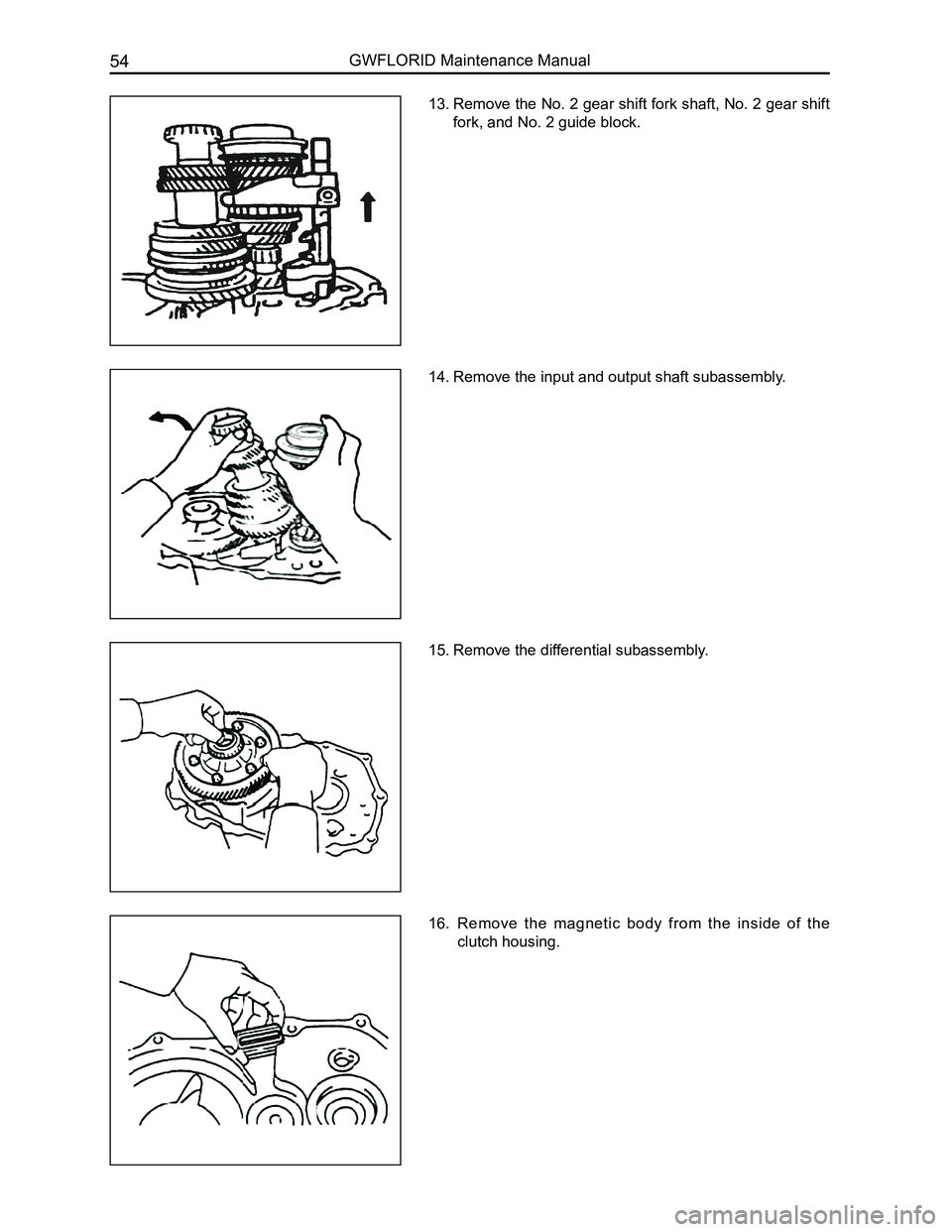
13. Remove the No. 2 gear shift fork shaft, No. 2 gear shift
fork, and No. 2 guide block.
14. Remove the input and output shaft subassembly.
15. Remove the differential subassembly.
16. Remove the magnetic body from the inside of the
clutch housing.
Page 62 of 281
Downloaded from www.Manualslib.com manuals search engine 55Transmission
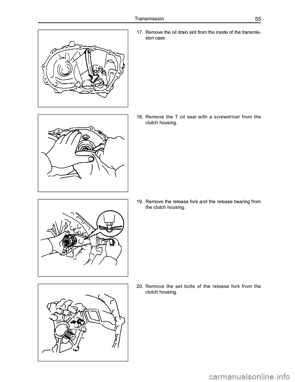
17. Remove the oil drain slot from the inside of the transmis-
sion case.
18. Remove the T oil seal with a screwdriver from the
clutch housing.
19. Remove the release fork and the release bearing from
the clutch housing.
20. Remove the set bolts of the release fork from the
clutch housing.
Page 63 of 281
Downloaded from www.Manualslib.com manuals search engine GWFLORID Maintenance Manual56
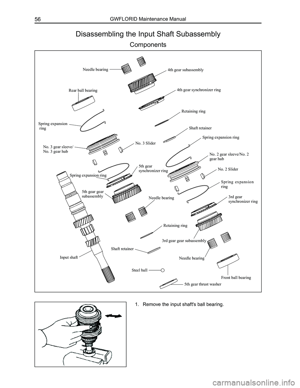
Disassembling the Input Shaft Subassembly
Components
Input shaft
Rear ball bearing
No. 3 gear sleeve/
No. 3 gear hub
No. 3 Slider
Spring expansion ring
5th gear synchronizer ring
5th gear gear subassemblyNeedle bearing
Retaining ring
Shaft retainer
Steel ball
5th gear thrust washer
Needle bearing4th gear subassembly
4th gear synchronizer ring
Retaining ring
Shaft retainer
No. 2 gear sleeve/No. 2 gear hub
No. 2 Slider
Spring expansion ring
3rd gear synchronizer ring
Needle bearing
Front ball bearing
3rd gear gear subassembly
Spring expansion ring
Spring expansion ring
1. Remove the input shaft's ball bearing.
Page 64 of 281
Downloaded from www.Manualslib.com manuals search engine 57Transmission
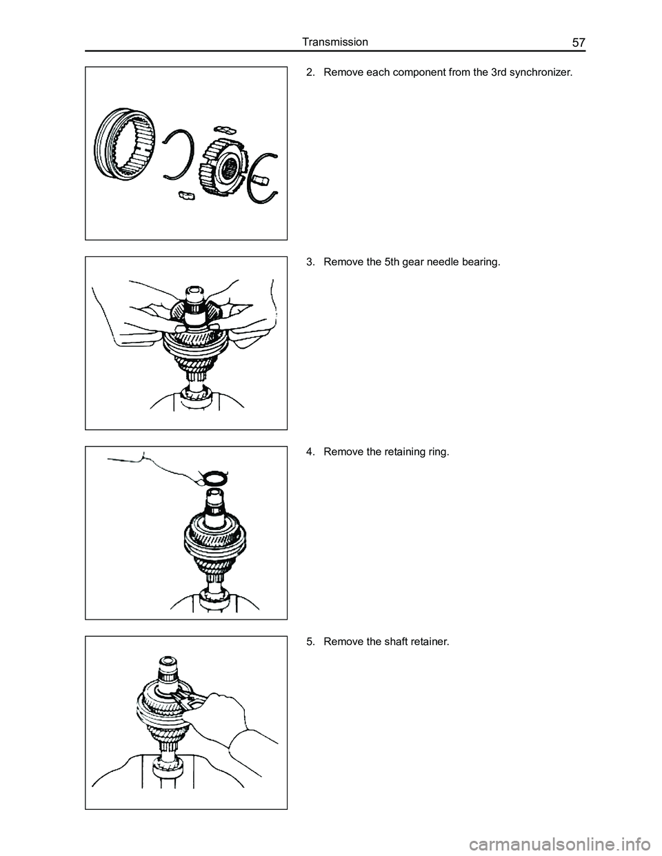
2. Remove each component from the 3rd synchronizer.
3. Remove the 5th gear needle bearing.
4. Remove the retaining ring.
5. Remove the shaft retainer.
Page 65 of 281
Downloaded from www.Manualslib.com manuals search engine GWFLORID Maintenance Manual58
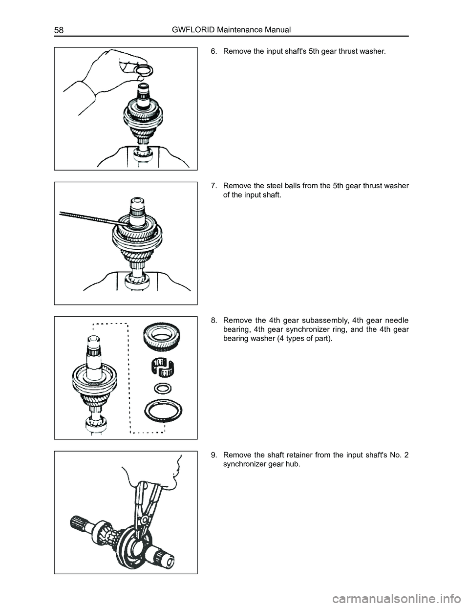
6. Remove the input shaft's 5th gear thrust washer.
7. Remove the steel balls from the 5th gear thrust washer
of the input shaft.
8. Remove the 4th gear subassembly, 4th gear needle
bearing, 4th gear synchronizer ring, and the 4th gear
bearing washer (4 types of part).
9. Remove the shaft retainer from the input shaft's No. 2
synchronizer gear hub.
Page 66 of 281
Downloaded from www.Manualslib.com manuals search engine 59Transmission
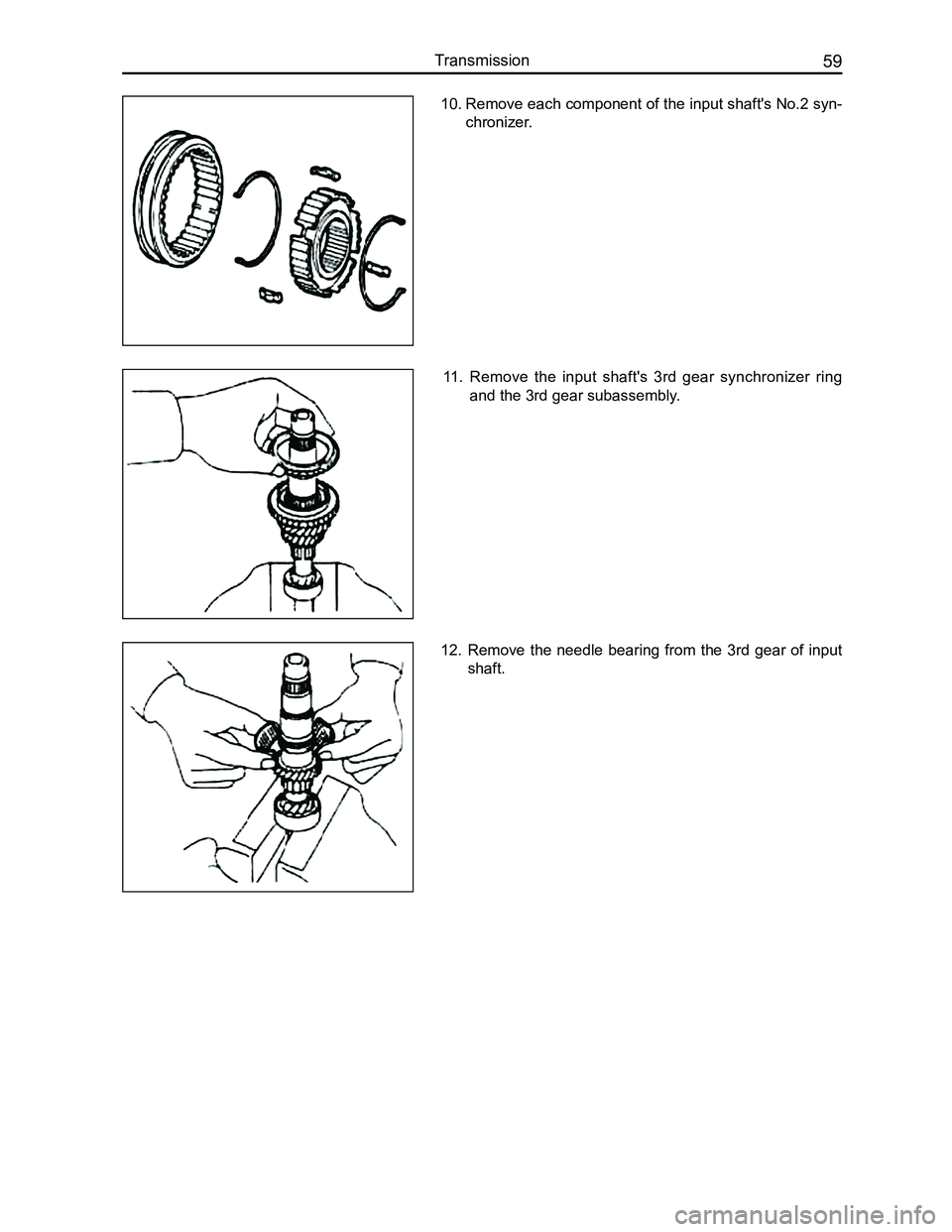
10. Remove each component of the input shaft's No.2 syn-
chronizer.
11. Remove the input shaft's 3rd gear synchronizer ring
and the 3rd gear subassembly.
12. Remove the needle bearing from the 3rd gear of input
shaft.
Page 67 of 281
Downloaded from www.Manualslib.com manuals search engine GWFLORID Maintenance Manual60
Disassembling the Output Shaft Subassembly
Components
Front tapered roller bearing
Output shaft
Needle bearing
1st gear gear subassembly
1st gear synchronizer ring
No. 1 gear sleeve/No. 1 gear hub
No. 1 Slider
Spring expansion ring
Shaft retainer
Retaining ring
Needle bearing
2nd gear synchronizer ring
2nd gear gear subassembly
3rd driven gear
Spacer
4th driven gear
5th driven gear
Shaft retainer
Rear tapered roller bearing
1. Remove the output shaft's rear tapered roller bearing.
Page 68 of 281
Downloaded from www.Manualslib.com manuals search engine 61Transmission
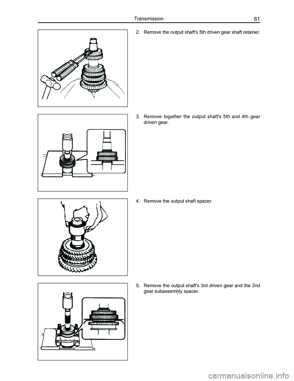
2. Remove the output shaft's 5th driven gear shaft retainer.
3. Remove together the output shaft's 5th and 4th gear
driven gear.
4. Remove the output shaft spacer.
5. Remove the output shaft's 3rd driven gear and the 2nd
gear subassembly spacer.
Page 69 of 281
Downloaded from www.Manualslib.com manuals search engine GWFLORID Maintenance Manual62
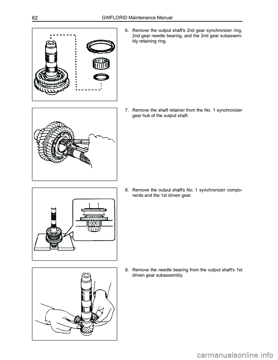
6. Remove the output shaft's 2nd gear synchronizer ring,
2nd gear needle bearing, and the 2nd gear subassem-
bly retaining ring.
7. Remove the shaft retainer from the No. 1 synchronizer
gear hub of the output shaft.
8. Remove the output shaft's No. 1 synchronizer compo-
nents and the 1st driven gear.
9. Remove the needle bearing from the output shaft's 1st
driven gear subassembly.
Page 70 of 281
Downloaded from www.Manualslib.com manuals search engine 63Transmission
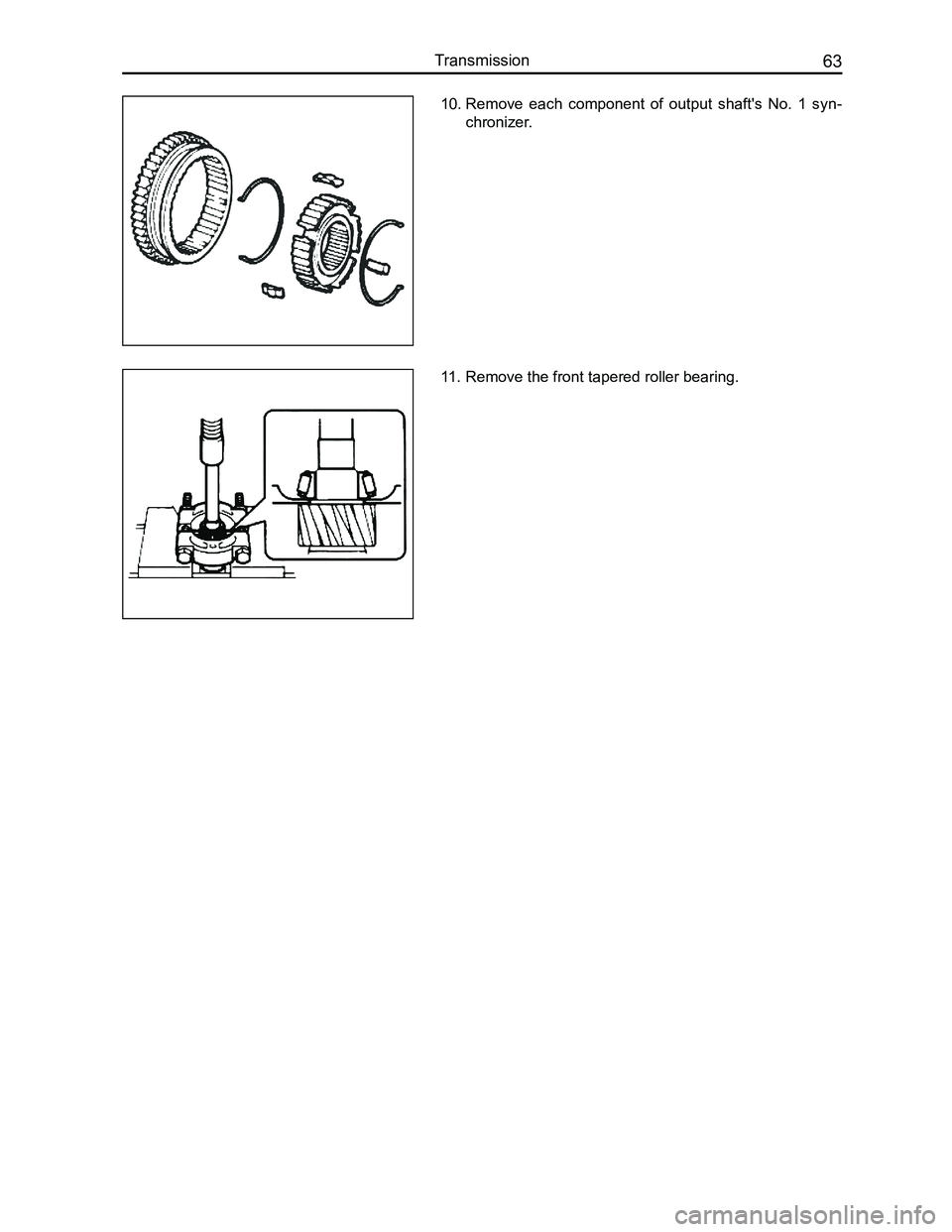
10. Remove each component of output shaft's No. 1 syn-
chronizer.
11. Remove the front tapered roller bearing.
Trending: window, door lock, ECU, lights, fuse diagram, coolant, charging
