power steering HONDA CIVIC COUPE 1999 Owners Manual
[x] Cancel search | Manufacturer: HONDA, Model Year: 1999, Model line: CIVIC COUPE, Model: HONDA CIVIC COUPE 1999Pages: 269, PDF Size: 2.42 MB
Page 46 of 269
Additional Information About Your SRS
SRS Components
Your Supplemental Restraint System (SRS) includes: Two front airbags. The driver's
airbag is stored in the center of
the steering wheel; the front
passenger's airbag is stored in the dashboard. Both are marked "SRS
AIRBAG." Sensors that can detect a
moderate to severe frontal
collision. A sophisticated electronic system
that continually monitors thesensors, control unit, the airbag
activators, and all related wiring
when the ignition is ON (II). An indicator light on the
instrument panel that alerts you to
a possible problem with thesystem (see page 47). Emergency backup power in case
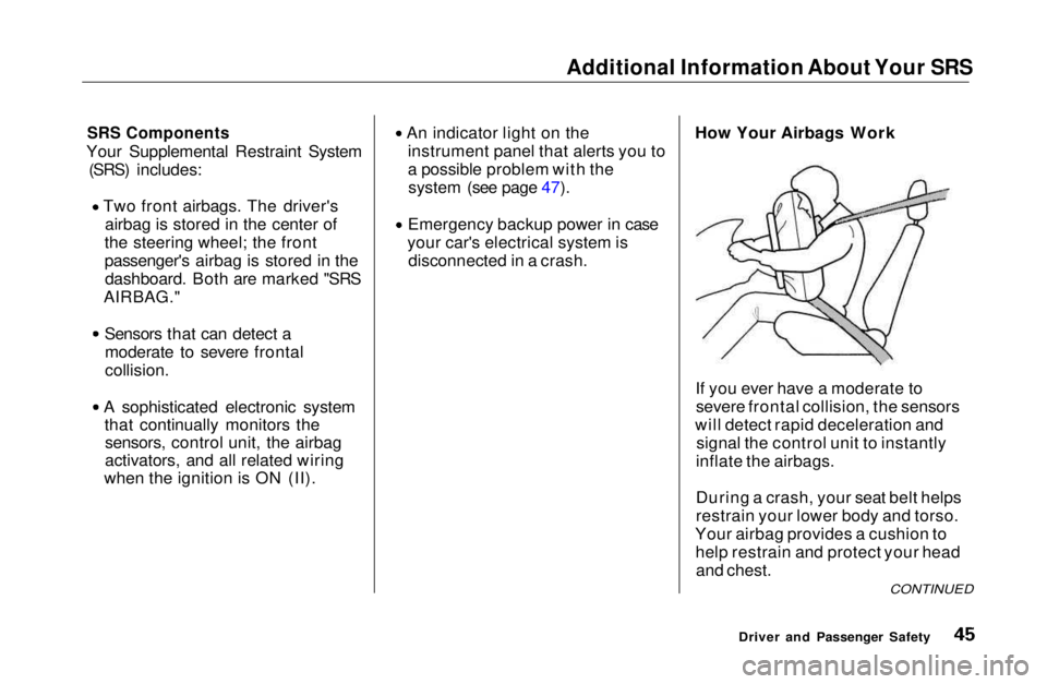
your car's electrical system is disconnected in a crash. How Your Airbags Work
If you ever have a moderate tosevere frontal collision, the sensors
will detect rapid deceleration and signal the control unit to instantly
inflate the airbags.
During a crash, your seat belt helps
restrain your lower body and torso.
Your airbag provides a cushion to help restrain and protect your headand chest.
Driver and Passenger Safety
CONTINUEDMain Menu Table of Contents s t
Page 52 of 269
Instruments and Controls
This section gives information about
the controls and displays thatcontribute to the daily operation of
your Honda. All the essential
controls are within easy reach.
Control Locations............................ 52
Indicator Lights................................ 53
Gauges.............................................. 57
Speedometer................................ 57
Tachometer.................................. 57
Odometer...................................... 57
Trip Meter.................................... 57
Fuel Gauge................................... 58
Temperature Gauge.................... 58
Maintenance Required
Indicator.................................... 59
Controls Near the Steering Wheel........................................ 60
Headlights.................................... 61
Daytime Running Lights............. 61
Instrument Panel Brightness..... 62
Turn Signals................................. 62
Windshield Wipers...................... 63
Windshield Washers................... 63
Hazard Warning........................... 64
Rear Window Defogger.............. 64
Steering Wheel Adjustment....... 65
Steering Wheel Controls ................ 66 Cruise Control.............................. 66
Keys and Locks................................ 69
Keys.............................................. 69
Ignition Switch............................. 69
Door Locks................................... 70
Power Door Locks....................... 71
Remote Transmitter.................... 72
Trunk............................................ 75
Seat Adjustments............................. 76
Front Seat Adjustments.............. 76
Rear Seat Access......................... 77
Head Restraints........................... 77
Folding Rear Seat............................ 78
Power Windows............................... 79
Moonroof.......................................... 81
Mirrors.............................................. 81
Adjusting the Power Mirrors..... 82
Parking Brake.................................. 83 Glove Box......................................... 83
Beverage Holder.............................. 84
Accessory Power Socket................ 85
Ashtrays............................................ 85
Interior Light.................................... 86
Instruments and ControlsMain Menu s t
Page 71 of 269
Keys and Locks
LOCK (0) — You can insert or
remove the key only in this position.
To switch from ACCESSORY to LOCK, you must push the key inslightly as you turn it. If your car has
an automatic transmission, the shift
lever must also be in Park. The anti-
theft lock will lock the steering column when you remove the key.
If the front wheels are turned, theanti-theft lock may sometimes make
it difficult to turn the key fromLOCK to ACCESSORY. Firmly turn
the steering wheel to the left or to
the right as you turn the key. ACCESSORY (I) — In this position,
you can operate the audio systemand the accessory power socket.
ON (II) — This is the normal key
position when driving. All features
and accessories on the car are usable.
Several of the lights on the instru-
ment panel come on as a test when
you turn the ignition switch from
ACCESSORY to ON.
START (III) — Use this position
only to start the engine. The switch
returns to ON (II) when you let go of
the key.
You will hear a reminder beeper if you leave the key in the ignition switch in the LOCK (0) or
ACCESSORY (I) position and open the driver's door. Remove the key toturn off the beeper.
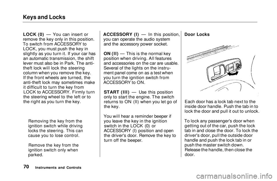
Door Locks
Each door has a lock tab next to the
inside door handle. Push the tab in to
lock the door and pull it out to unlock.
To lock any passenger's door when getting out of the car, push the lock
tab in and close the door. To lock thedriver's door, pull the outside door
handle and push the lock tab in or
push the master switch down. Release the handle, then close the
door.
Instruments and Controls
Removing the key from the
ignition switch while driving
locks the steering. This can
cause you to lose control.
Remove the key from the
ignition switch only when
parked.Main Menu Table of Contents s t
Page 156 of 269
Maintenance
This section explains why it is important to keep your car wellmaintained and to follow basic
maintenance safety precautions.
This section also includes Maintenance Schedules for normal
driving and severe driving conditions,
a Maintenance Record, and instruc-
tions for simple maintenance tasks
you may want to take care of yourself.
If you have the skills and tools to per-form more complex maintenance
tasks on your Honda, you may want
to purchase the Service Manual. See
page 263 for information on how to obtain a copy, or see your Honda
dealer.
Maintenance Safety....................... 158
Important Safety Precautions.. 159
Maintenance Schedule.................. 160
Maintenance Record..................... 167 Owner Maintenance Checks........ 169
Fluid Locations............................... 170
Engine Oil....................................... 171
Adding Oil................................... 171
Recommended Oil..................... 171Synthetic Oil............................... 172
Additives..................................... 172
Changing the Oil and Filter...... 173
Cooling System.............................. 175
Adding Engine Coolant............. 175Replacing Engine Coolant........ 177
Windshield Washers..................... 180
Transmission Fluid........................ 180
Automatic
Transmission.......................... 180
5-speed Manual
Transmission.......................... 182
Brake and Clutch Fluid................. 182
Brake System............................. 183
Clutch System............................ 183
Power Steering............................... 184
Air Cleaner Element...................... 185 Hood Latch..................................... 186
Spark Plugs..................................... 187
Replacement............................... 187
Specifications............................. 188
Battery............................................ 189
Wiper Blades.................................. 191
Air Conditioning System............... 193 Drive Belts...................................... 194
Timing Belt..................................... 194
Tires................................................ 195 Inflation....................................... 195
Recommended Tire Pressures
for Normal Driving............ 196
Inspection................................... 197
Maintenance............................... 197
Tire Rotation.............................. 198
Replacing Tires and Wheels .... 199
Wheels and Tires....................... 200
Winter Driving........................... 200
Snow Tires.............................. 200
Tire Chains............................. 201
Lights.............................................. 202 Replacing Bulbs......................... 204
Storing Your Car............................ 212
MaintenanceMain Menu s t
Page 169 of 269
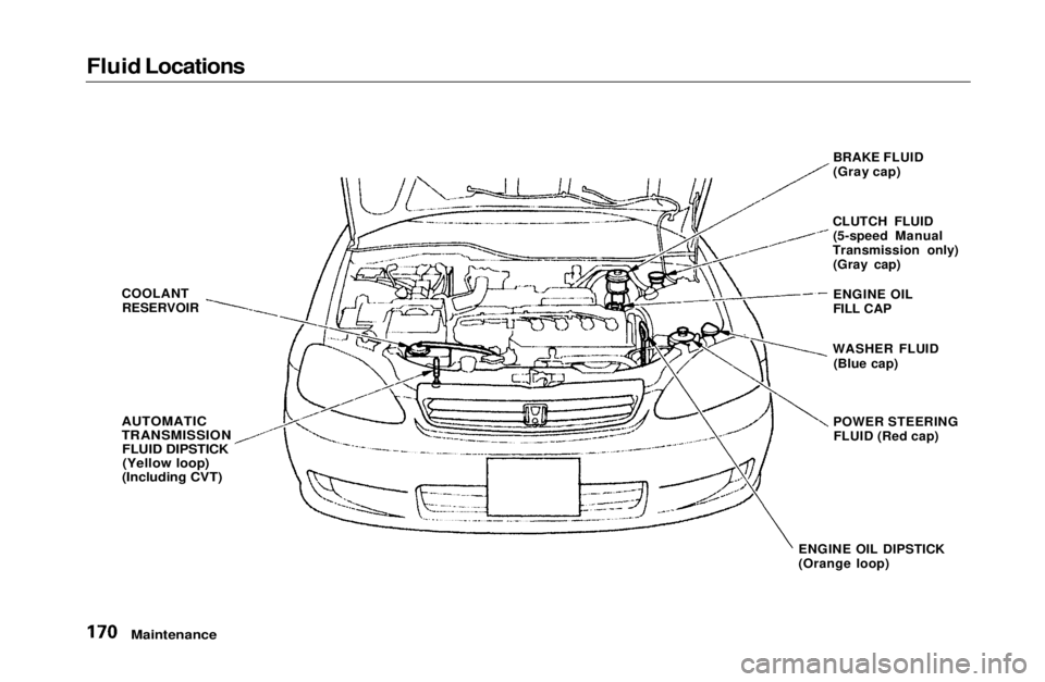
Fluid Locations
Maintenance
COOLANT
RESERVOIR
AUTOMATIC
TRANSMISSION
FLUID DIPSTICK(Yellow loop)
(Including CVT)
BRAKE FLUID
(Gray cap)
CLUTCH FLUID (5-speed Manual
Transmission only) (Gray cap)
ENGINE OIL DIPSTICK
(Orange loop) ENGINE OIL
FILL CAP
WASHER FLUID (Blue cap)
POWER STEERING FLUID (Red cap)Main Menu Table of Contents s t
Page 183 of 269
Power Steering
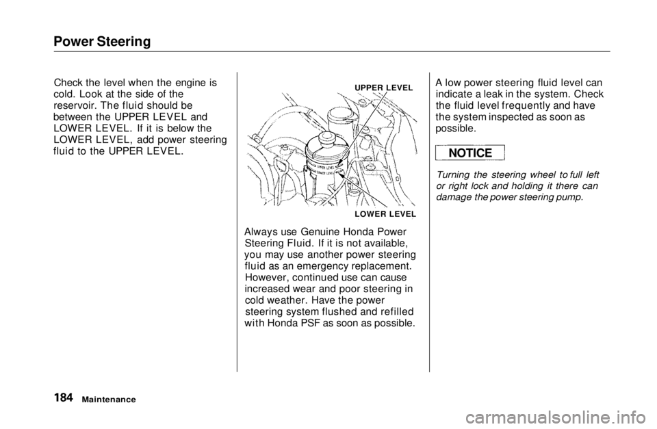
Check the level when the engine is
cold. Look at the side of the
reservoir. The fluid should be
between the UPPER LEVEL and LOWER LEVEL. If it is below the
LOWER LEVEL, add power steering
fluid to the UPPER LEVEL.
Always use Genuine Honda PowerSteering Fluid. If it is not available,
you may use another power steering fluid as an emergency replacement.However, continued use can cause
increased wear and poor steering in cold weather. Have the powersteering system flushed and refilled
with Honda PSF as soon as possible. A low power steering fluid level can
indicate a leak in the system. Check
the fluid level frequently and have
the system inspected as soon as
possible.
Turning the steering wheel to full left
or right lock and holding it there can
damage the power steering pump.
Maintenance
NOTICE
UPPER LEVEL
LOWER LEVELMain Menu Table of Contents s t
Page 193 of 269
Drive Belts, Timing Belt
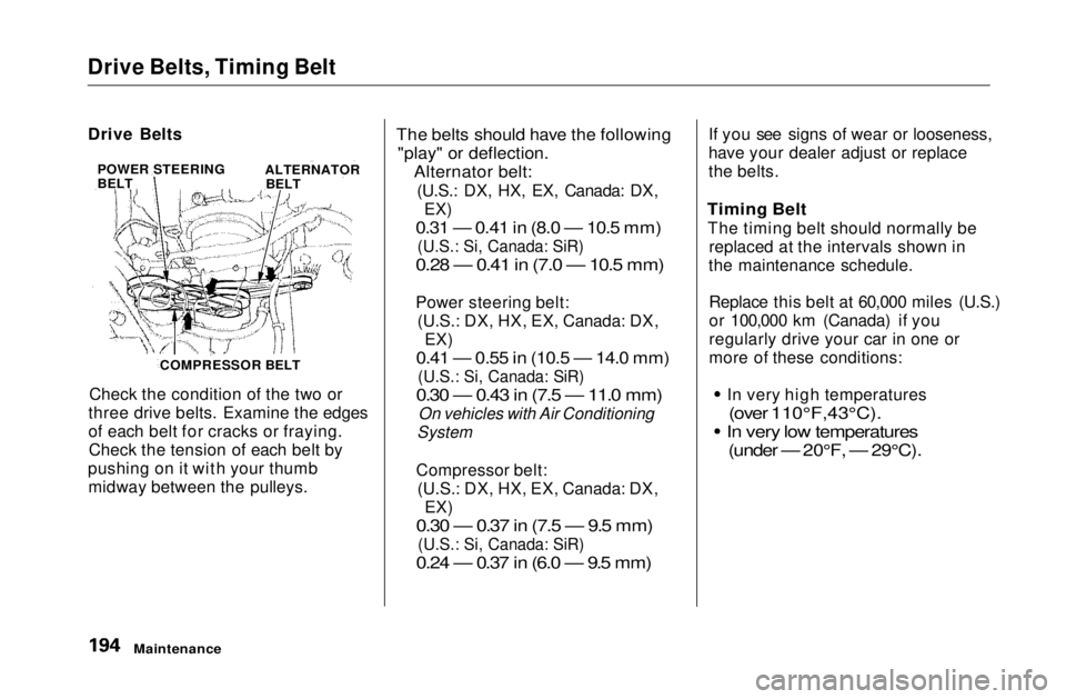
Check the condition of the two or
three drive belts. Examine the edges
of each belt for cracks or fraying. Check the tension of each belt by
pushing on it with your thumb midway between the pulleys.
The belts should have the following
"play" or deflection.
Alternator belt:
(U.S.: DX, HX, EX, Canada: DX,
EX)
0.31 — 0.41 in (8.0 — 10.5 mm)
(U.S.: Si, Canada: SiR)
0.28 — 0.41 in (7.0 — 10.5 mm)
Power steering belt: (U.S.: DX, HX, EX, Canada: DX, EX)
0.41 — 0.55 in (10.5 — 14.0 mm)
(U.S.: Si, Canada: SiR)
0.30 — 0.43 in (7.5 — 11.0 mm)
On vehicles with Air Conditioning
System
Compressor belt: (U.S.: DX, HX, EX, Canada: DX,
EX)
0.30 — 0.37 in (7.5 — 9.5 mm)
(U.S.: Si, Canada: SiR)
0.24 — 0.37 in (6.0 — 9.5 mm)
If you see signs of wear or looseness,
have your dealer adjust or replace
the belts.
Timing Belt
The timing belt should normally be replaced at the intervals shown in
the maintenance schedule.
Replace this belt at 60,000 miles (U.S.)
or 100,000 km (Canada) if you
regularly drive your car in one or
more of these conditions:
In very high temperatures
(over 110°F,43°C).
In very low temperatures
(under — 20°F, — 29°C).
Maintenance
Drive Belts
POWER STEERING
BELT ALTERNATOR
BELT
COMPRESSOR BELTMain Menu Table of Contents s t
Page 203 of 269
Lights
Replacing a Headlight Bulb
Your car has halogen headlight bulbs, one on each side. When
replacing a bulb, handle it by its steel
base and protect the glass fromcontact with your skin or hard
objects. If you touch the glass, clean
it with denatured alcohol and a clean
cloth.
Halogen headlight bulbs get very hot when lit. Oil, perspiration, or a scratch
on the glass can cause the bulb to
overheat and shatter.
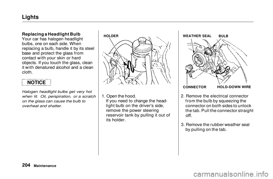
1. Open the hood.
If you need to change the head-
light bulb on the driver's side, remove the power steeringreservoir tank by pulling it out of
its holder.
2. Remove the electrical connector
from the bulb by squeezing theconnector on both sides to unlock
the tab. Pull the connector straight
off.
3. Remove the rubber weather seal by pulling on the tab.
Maintenance
NOTICE
HOLDER
WEATHER SEAL
BULB
CONNECTOR
HOLD-DOWN WIREMain Menu Table of Contents s t
Page 204 of 269
Lights
4. Unclip the end of the hold-down wire from its slot. Pivot it out ofthe way and remove the bulb.
5. Insert the new bulb into the hole, making sure the tabs are in theirslots. Pivot the hold-down wire
back in place and clip the end into
the slot.
6. Install the rubber seal over the back of the headlight assembly.Make sure it is right side up; it is
marked "TOP."
7. Push the electrical connector onto the tabs of the new bulb. Makesure it locks in place.
Turn on the headlights to test the new bulb.
8. (Driver's side) Reinstall the power steering
reservoir.
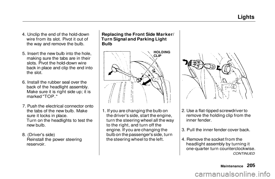
Replacing the Front Side Marker/
Turn Signal and Parking Light Bulb
1. If you are changing the bulb on the driver's side, start the engine,
turn the steering wheel all the way
to the right, and turn off the
engine. If you are changing the
bulb on the passenger's side, turn
the steering wheel to the left. 2. Use a flat-tipped screwdriver to
remove the holding clip from the
inner fender.
3. Pull the inner fender cover back.
4. Remove the socket from the headlight assembly by turning it
one-quarter turn counterclockwise.
CONTINUED
Maintenance
HOLDING
CLIPMain Menu Table of Contents s t
Page 241 of 269
Emergency Towing
plugged into the accessory powersocket are turned off so they do not
run down the battery.
Trying to lift or tow your vehicle by
the bumpers will cause serious
damage. The bumpers are not designed to support the vehicle's
weight.
Taking Care of the Unexpected
The steering system can be
damaged if the steering wheel is locked. Leave the ignition switch in
Accessory (I), and make sure the steering wheel turns freely before
you begin towing.
NOTICE
NOTICEMain Menu Table of Contents s t