HONDA INTEGRA 1994 4.G Workshop Manual
Manufacturer: HONDA, Model Year: 1994, Model line: INTEGRA, Model: HONDA INTEGRA 1994 4.GPages: 1413, PDF Size: 37.94 MB
Page 991 of 1413
Seat Belts
lnspection
Retractol InsDection
1. Before installing the retractor, check that the seat
belt can be pulled out freely.
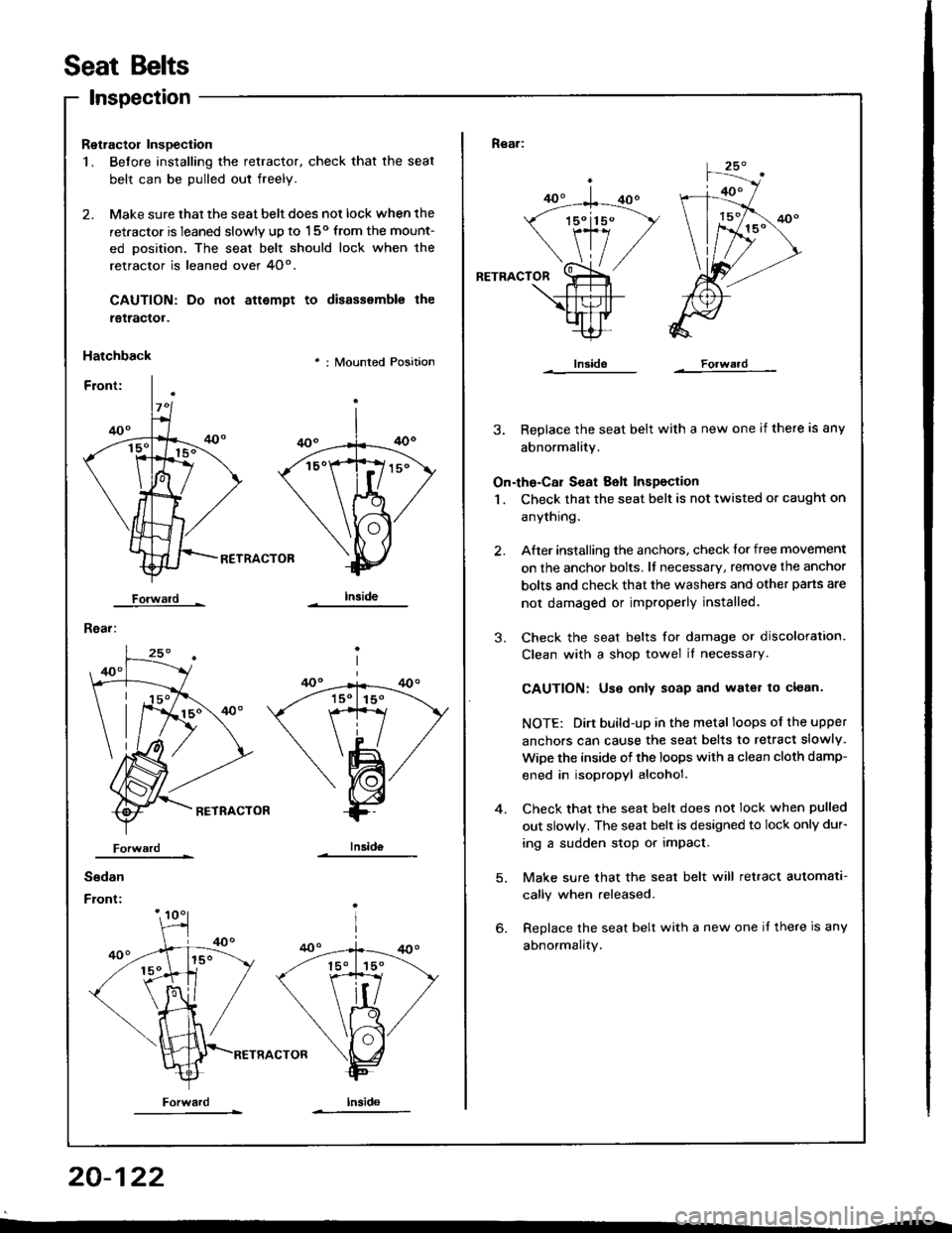
2. Make sure that the seat belt does not lock when the
retractor is leaned slowly up to 150 from the mount-
ed oosition. The seal belt should lock when the
retractor is leaned over 4O".
CAUTION: Do
tgtractol.
Hatchback
Forwald -
Rear:
not attempt to disassemble the
' : Mounted Position
RETRACTOB
Iniid6
Sedan
Front:
Forwardlnsido
Forward
Rear:
RETRACTOR
3. Replace the seat belt with a new one if there is any
abnormality.
On-the-Cal S€at Belt Inspection
1 . Check that the seat belt is not twisted or caught on
anythrng.
After installing the anchors, check lor free movement
on the anchor bolts. lf necessary, remove the anchor
bolts and check that the washers and other pans are
not damaged or improperly installed.
Check the seat belts for damage or discoloration.
Clean with a shop towel iI necessary.
CAUTION: Use only soap and water to clean.
NOTE: Dirt build-up in the metal loops of the upper
anchors can cause the seat belts to retract slowly.
WiDe the inside of the loops with a clean cloth damp-
ened in isopropyl alcohol.
Check that the seat belt does not lock when pulled
out slowly. The seat belt is designed to lock only dur-
ing a sudden stop or impact.
Make sure that the seat belt will retract automata-
cally when released.
Replace the seat belt with a new one it there is any
abnormality.
2.
3.
4.
20-122
Page 992 of 1413
Child Seat Anchor Plate
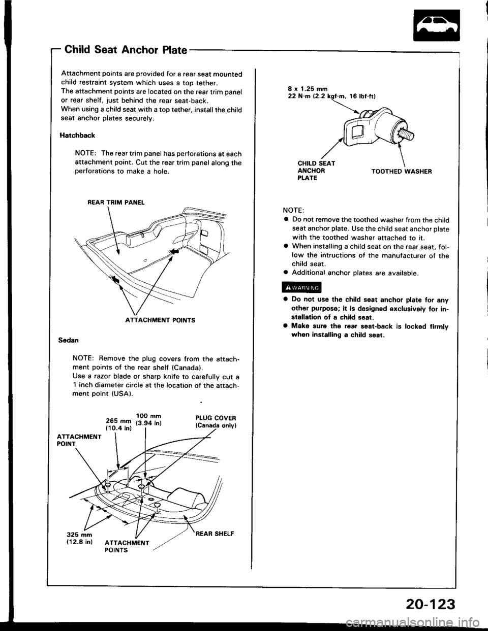
Attachment points are provided for a rear seat mountedchild restraint system which uses a top tether,
The attachment points are located on the rear trim panel
or rear shelf, just behind the rear seat-back.
When using a child seat with a top tether, installthe childseat anchor plates securely.
Hatchback
NOTE: The rear trim panel has perJorations at each
attachment point. Cut the rear trim panel along theperforations to make a hole,
Sedan
NOTE: Remove the plug covers from the attach-ment points of the rear shelf (Canada).
Use a razor blade or sharp knife to carefully cut a1 inch diameter circle at the location of the attach-ment point (USAI.
265 mm(10.4 inl
IOO mm13.94 inl
BEAR TRIM PANEL
ATTACHMENT POINTS
TOOTHED WASHER
NOTE:
a Do not remove the toothed washer from the child
seat anchor plate. Use the child seat anchor plate
with the toothed washer attached to it.a When installing a child seat on the rear seat, fol-low the intructions of the manufacturer of thechild seat,a Additional anchor plates are available.
a Do not use the child seat anchor plate for any
other puipos€; it is dosigned exclusively tor in-
stallation of a child seat.
a Mako sure tho roar seat-back is locked firmlvwh€n installing a child soat.
REAR SHELF
20-123
Page 993 of 1413
Garpet
Replacement
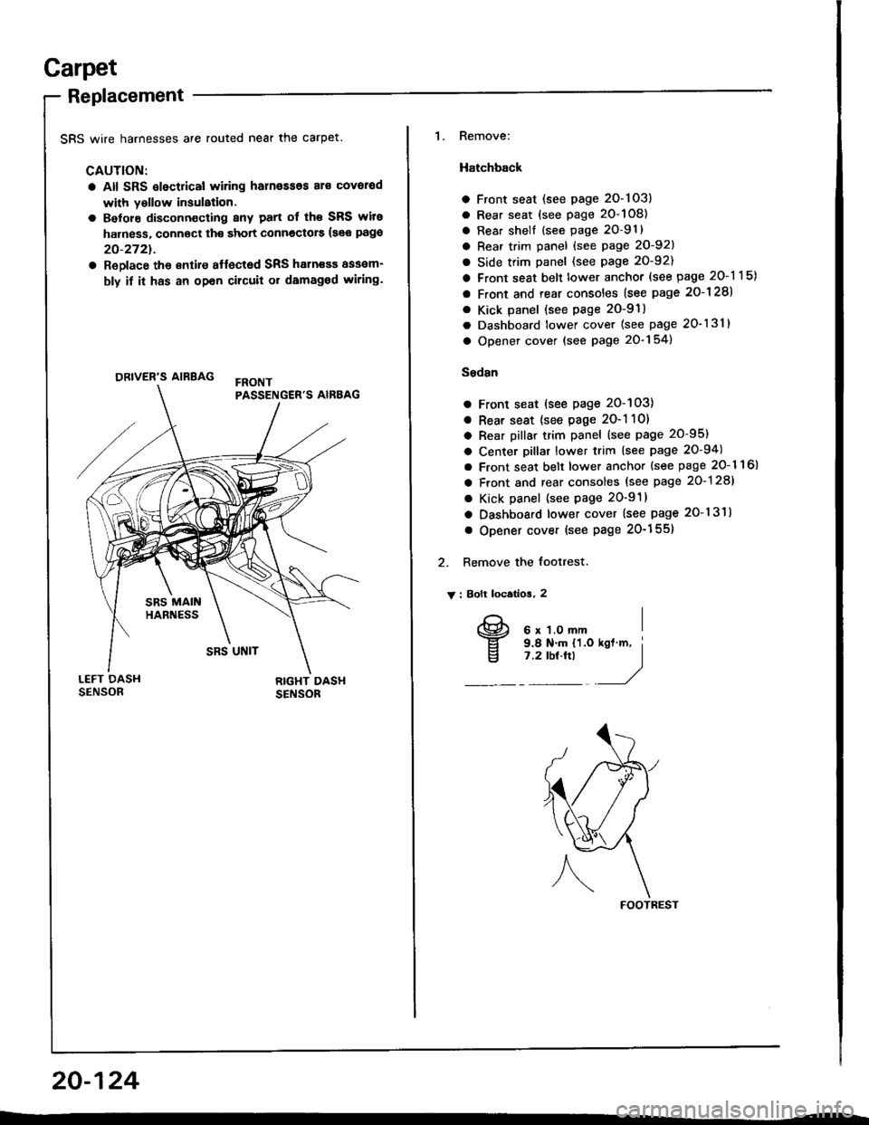
SRS wire harnesses are routed near the carpet.
CAUTION:
a All SRS slectrical wiring harn€ssos al€ covorod
with yollow insulation.
a Belore disconn€cting 8ny patt of th€ SRS wite
harness, connoct th€ short connectors {see pago
20-2721.
a ReDlace the €ntire affected SRS haln€sa assam-
bly if it has an opan cilcuit or damaged wiring.
ORIVER'S AIRBAG
1. Remove:
Hatchback
a Front seat (see page 2O-103)
a Rear seat (see page 20-108)
a Rear shell {see page 2O-91}
a Rear trim panel {see Page 20-921
a Side trim panel (see page 20-92)
a Front seat belt lower anchor (see page 20-115)
a Front and rear consoles (see page 2o-128)
. Kick panel (see page 2O-91)
a Dashboard lower cover (see page 20-131)
a Opener cover (see page 20-154)
Sedsn
a Front seat (see page 20-103)
a Rear seat {see page 2O-1 10)
a Rear pillar trim panel (see page 20-95)
a Center pillar lower trim (see page 20-94)
a Front seat belt lower anchor {see page 20- 1 1 6l
a Front and rear consoles (see page 20-128)
a Kick panel (see page 20-91)
a Dashboard lower cover (see page 20-131)
o Opener cover (see Page 20-155)
2. Remove the footrest.
V : Bolt locatios, 2
FOOTREST
20-124
I
v
6 x 1.O mm9.8 N.m {'l.o7 .2 tbt.ftl
Page 994 of 1413
: Push nul locatlon3, 5
DOOR SILL MOLDING
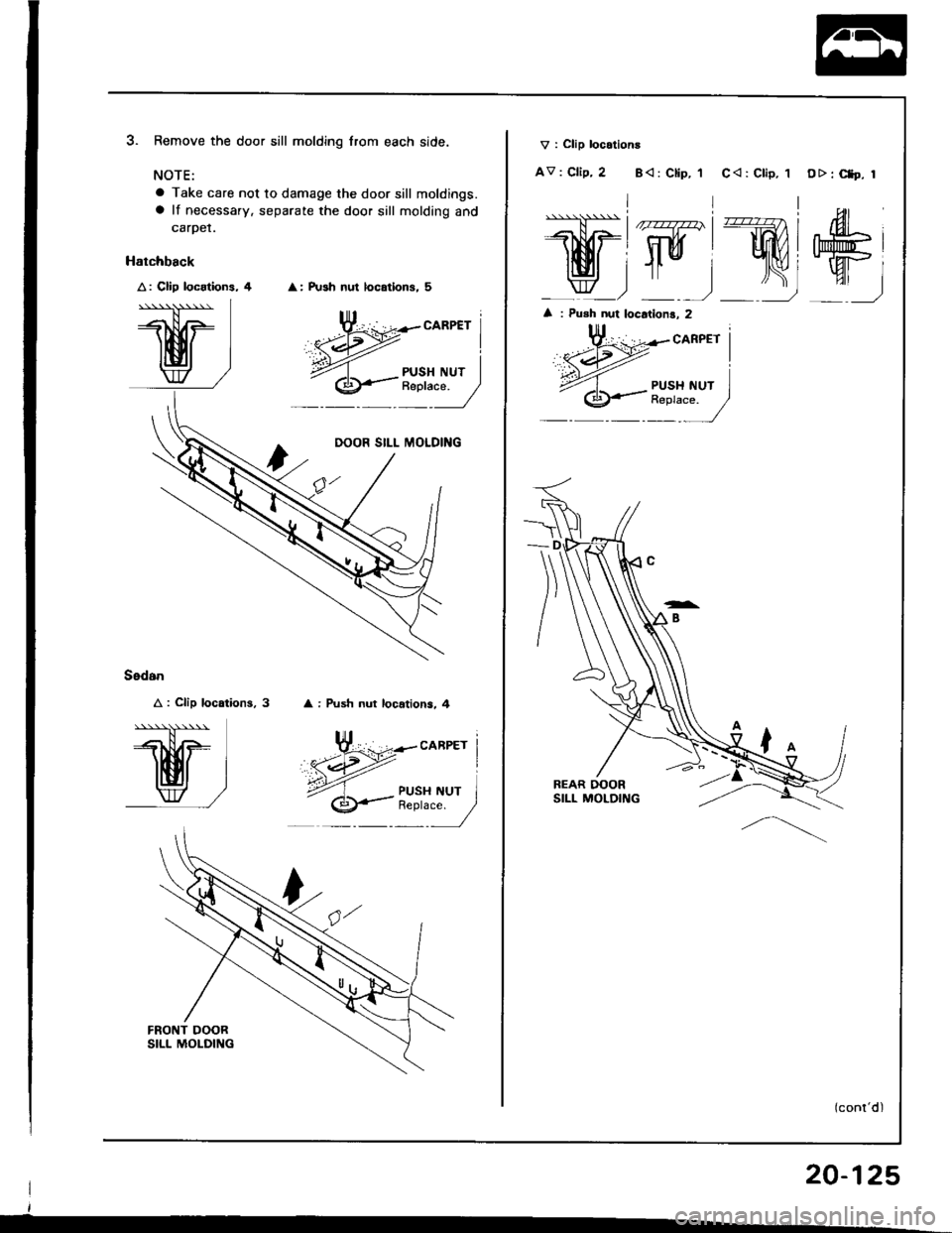
Remove the door sill molding lrom each side.
NOTE:
a Take care not to damage the door sill moldings.a lf necessary. separate the door sill molding and
carper.
: Push nut locations, 4
Sedan
A : Clip location3,
''*'N*
I EI I
w/
FRONT DOORSILL MOLDII{G
| 20-125
CARPET I
I
{ NUr I":-/
V : Clip locatlons
AV : Clip, 2 B< : Ctip, 'lC<: Clip, 1 O>: Ct9. r
.l\-\).\\1,------l- | /rryz)' | ru4l rA
lMi WIWI
_ w_) -) _)
: Push nut locations, 2
Page 995 of 1413
Carpet
Replacement (cont'd)
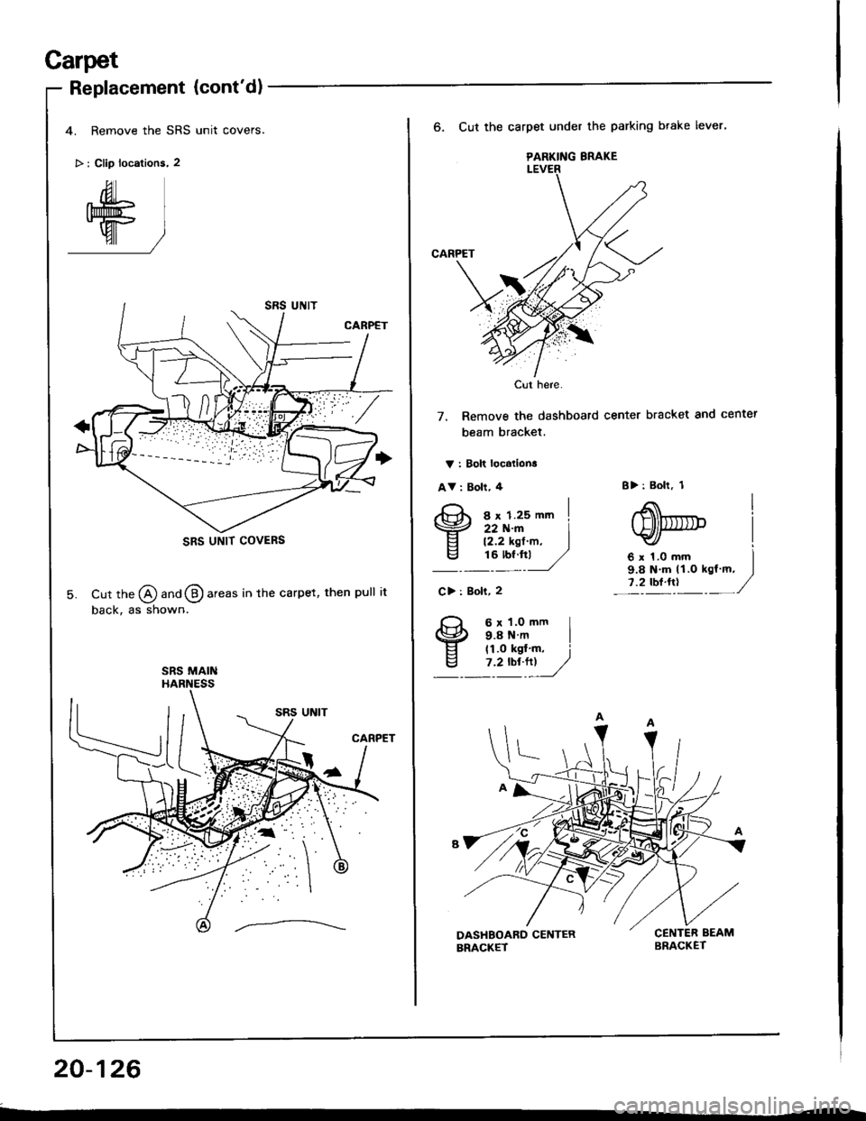
4. Remove the SRS unit covers.
> : Clip locations, 2
Cut tne @ ana @ areas in the carpet, then pull it
back, as shown.
SRS UNIT COVERS
SRS MAIN
20-126
PARKING BRAKE
Cut here.
6. Cut the carpet under the parking btake lever'
CARPET
7. Remove the dashboard center bracket and center
beam bracket.
V : Bolt locatlona
AV : Boll, 4
s x 1.2s mm I22 N.m I12.2 ksf m, I16 tbt.ftl /,/
B>: Bolt, 1
6x1.Omm I9.8 N'm tl.O kgl m, I
l:?'o'!"t -'/C> : goli, 2
6 x 1.0 ftm I9.8Nm I11.0 kst'm, i'1Y"!_/
Page 996 of 1413
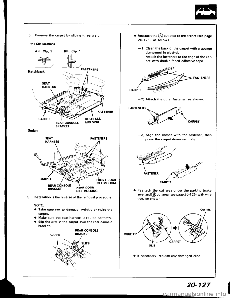
8. Remove the carpet by sliding it rearward.
V : Cllp loc6tions
AV : Clip, 3B>: Clip, 1
FASTENERS
:ft
r,,-,
Hatchback
CARPET
Ssdan
FASTENERS
SILL MOLDINGREAR CONSOLEBRACKETSILL MOLDING
Installation is the reverse of the removal procedure.
NOTE:
a Take care not to damage, wrinkle or twist the
carpet.
a Make sure the seat harness is routed correctly.a Slip the slits in the carpet over the rear console
bracket.
REAR CONSOLEBRACKET
a Reattach the @ cut area of the carpet {see page
20-126). as tollows.
- 1) Clean the back of the carpet with a sponge
damoened in alcohol.
Attach the fasteners to the edge of the car,
pet with double-faced adhesive tape.
FASTENERS
-2) Attach the other tastener. as shown.
FASTENERS
CARPET
-3) Align the carpet with the fastener,
press the carpet down securely.
then
CARPET
Reattach the cut area under the parking brake
lever and (9 cut area (see page 20-126) with wire
ties, as shown.
Cut otf.
WIRE TIE
a lf necessary, replace any damaged clips.
FASTENER
SLIT
20-127
Page 997 of 1413
Front and Rear Consoles
Replacement
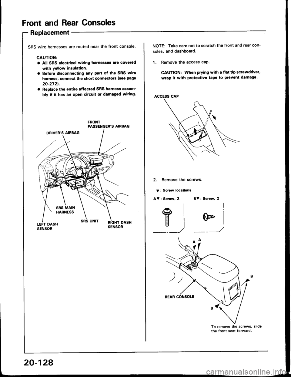
SRS wire harnesses are routed near the front console.
CAUTION:
a All SFS electrical wiring harnesses aro coverod
with y6llow insulalion.
a Betore disconnecting any part of lho SRS wire
harness, connect th€ short connoctorc (so€ pago
20-272t.
a Replaco tho sntilo aftocted SRS halness assom-
bly it it has an opon circuit or damaged wlring.
FBONTPASSENGER'S AIRBAG
20-128
NOTE: Take care not to scratch the tront and rear con-
soles, and dashboard.
1. Remove the access cap.
CAUTION: liYhen prying with a flat tip scr€wd.lv€r,
wrap it with protoctivo tape to provent damag€.
ACCESS CAP
2. Remove the sctews.
v : Scraw loc€tlona
At : Scr.w, 2 Bv : Scrow, 2
E)
w)
Page 998 of 1413
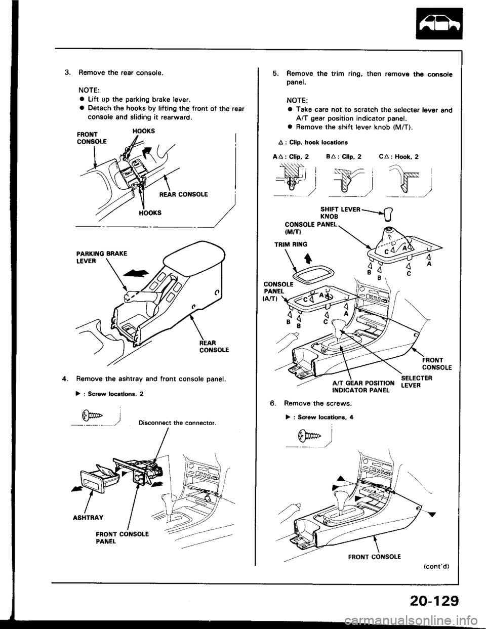
3.Remove the rear console,
NOTE:
a Lift up the parking brake lever.
a Oetach the hooks by lifting the front ot the rear
console and sliding it rearward.
Remove the sshtrsy and front console panel.
> : Scrow locatlon3, 2
Diaconn€ct the connector.
4.
l
5. Remove the trim ring, then remov€ th€ consolepanel.
NOTE:
a Take cafe not to scratch the selecter l6ver 8ndA/T gear position indicator panel.
a Remove the shiJt lever knob (M/T).
A : Cllp, hook loc.tions
AA : Clip, 2 BA : Cllp, 2 CA : Hook, 2
SHIFT I.EVERKNOB
CONSOLE PANEL
IM/TI
TRIM RI'{G
"onroar€
,"Hr"t z{o$
co soLE
POStTtONSELECTERLEVEBINDICATOR PANEL
6. Remove the screws.
> : Screw locationr, 4
6bo'' I:./
20-129
Page 999 of 1413
Front and Rear Consoles
Replacement (cont'd)
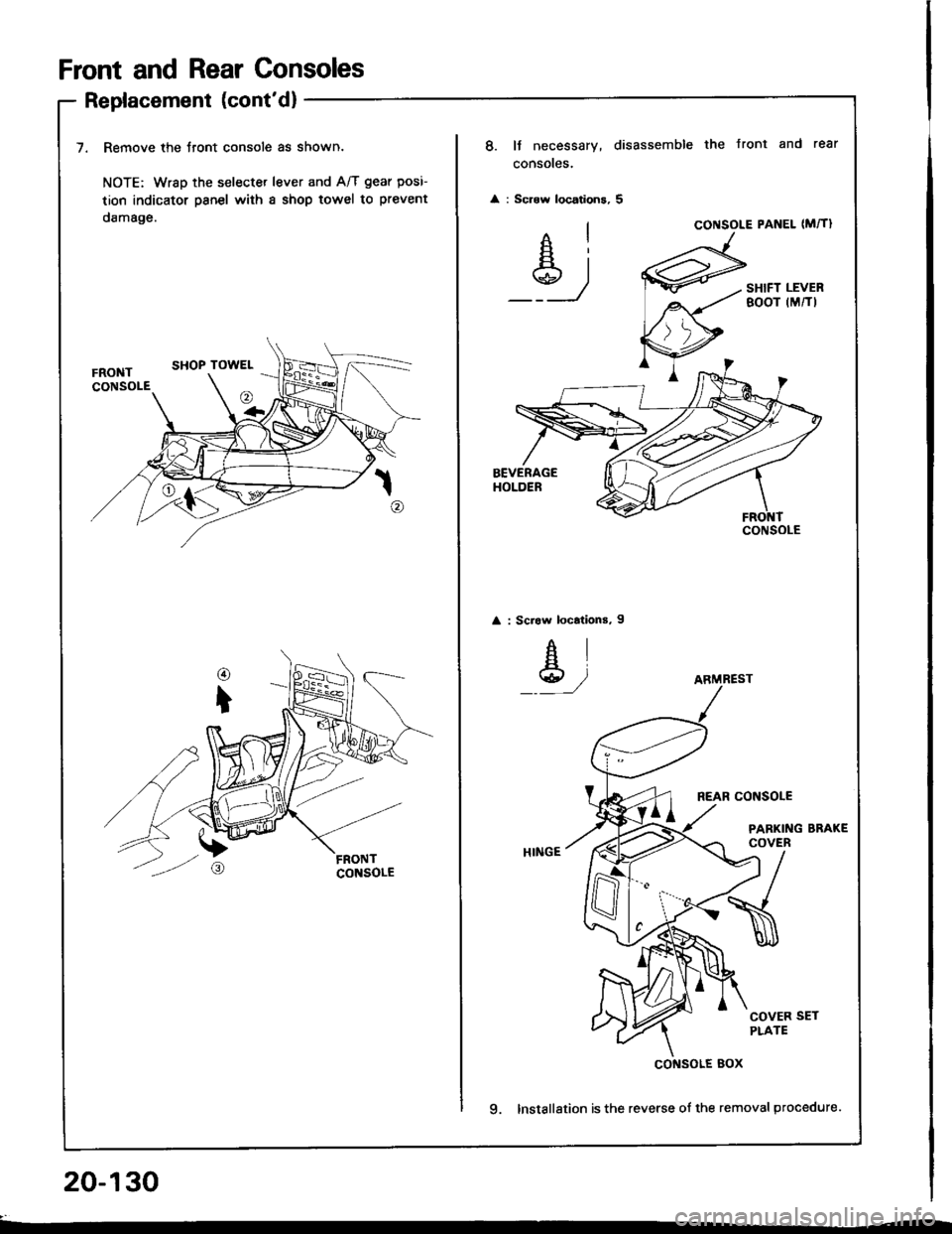
7. Remove the Jront console as shown.
NOTE: Wrsp the selecter lever and A/T gear posi-
tion indicator psnel with a shop towel to prevent
damage.
20-130
8. It necessary, disassemble the Jront and rear
consoles.
: Scrow locations, 5
Ai
_Y_)
CONSOLE PANEL (M�TI
SHIFT LEVERBOOT (M/TI
: Scraw locations, I
AI
Y,/
REAR CONSOLE
PARKING BRAKECOVER
COVER SETPLATE
9. Installation is the reverse of the removal procedure.
CONSOLE
ARMREST
cof{solE Box
Page 1000 of 1413
Dashboard
Component Removal/lnstallation
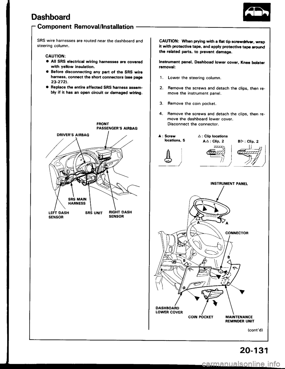
SRS wire harnesses are routed near the dashboard andsteering column.
CAUTION:
a All SRS olectrical wiring harnesses ar6 covolodwith yallow insulation.
a Betoro disconnecting any paft ot th6 SRS wiro
harn€ss, connoct th€ shoi connectots (s66 page
23-2721.
a Replaco th€ entire Itlocted SRS hsrness asaem-
bly il h has an open circuh or damagod wiring.
CAUTION: Whan prying with a flat tip scrowdiv... wrapit with protoctiv€ tape, and apply protectivo tapo a.oundth€ felatsd parts. to provent damag€.
Instiumont p8n6l, Dashboad lower covor. Knec bobtcframoval:
l. Lower the steering column.
2. Remove the screws and detach the cliDs, then re-
move the instrument panel.
3. Remove the coin oocket.
4. Remove the screws and detach the clips, then re-
move the dashboard lower cover.
Disconnect the connector.
: Scrawlocation3, 5
AIF|]A\g)
A i Clip locationg
AA: Cllp, 2 B> : Clip, 2
I l-l L'l| ,-__-, )
itrvi
) 4Z)
_:n,,4<-ft
INSTRUMENT PAI{EL
(cont'd)
COIN POCKET
20-131