HONDA INTEGRA 1994 4.G Workshop Manual
Manufacturer: HONDA, Model Year: 1994, Model line: INTEGRA, Model: HONDA INTEGRA 1994 4.GPages: 1413, PDF Size: 37.94 MB
Page 1031 of 1413
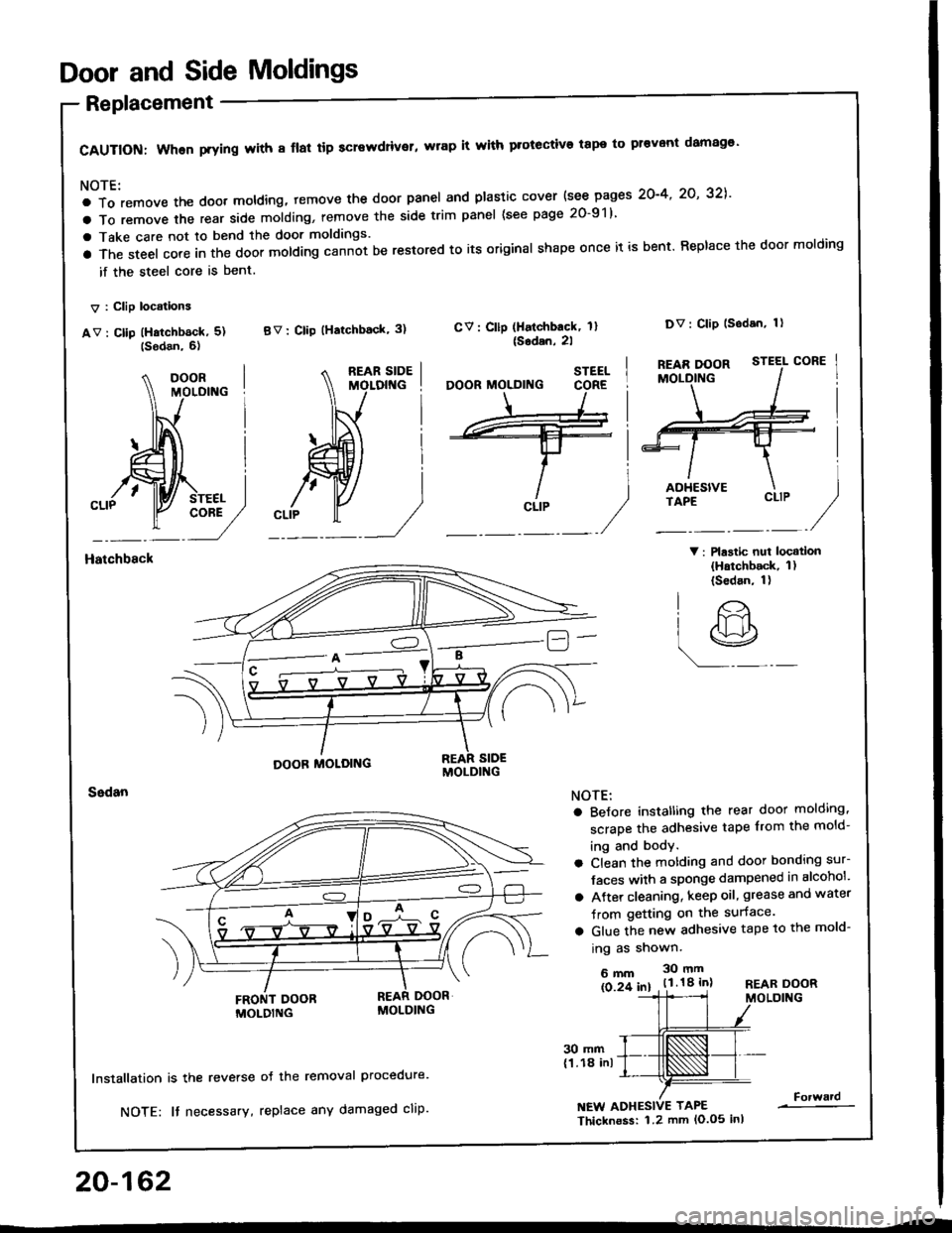
Door and Side Moldings
Replacement
CAUTION: When prying with 8 flal tip screwdriver, wrap it with protective tape to pr€vont damag€'
NOTE:
a To remove the doot moldlng, temove the door panel and plastic cover {see pages 2O-4' 2O' 32],'
a To remove the rear side molding, remove the side trim panel (see page 20-91)
a Take care not to bend the door moldings.
a The steel core in the door molding cann-ot be restored to its original shape once it is bent. Replace the door molding
if the steel core is bent.
V : Clip locations
av : cllp (Hatchb6ck, 5) BV: clip (Hatchback' 3)
V: Plastic nui locatlon(Hatchback, 1)(Sedan, 1)
CV: Cllp (Halchback, 1l{Sodan,2l
Dv: Clip lsodan, 1)
Hatchbsck
20-162
30 mm(1.18 inl
lnstallation is the reverse
NOTE: It necessary,
oJ the removal Procedure.
replace any damaged cliP.NEW ADHESIVE TAPE
Thicknoss: 1.2 mm lo.o5 inl
Forward
STEEL
CLIP
O'
lr>
r9
NOTE:
a BeJore instatling the rear door molding,
scrape the adhesive tape from the mold-
ing and body.
a Clean the motding and door bonding sur-
Jaces with a sponge dampened in alcohol'
a Atter cleaning, keep oil, grease and water
Jrom getting on the surface.
a Glue the new adhesive tape to the mold-
ing as shown.
6mm 30mm
ls 2f 61 . t.l.18 inlREAR DOORMOLDING
Page 1032 of 1413
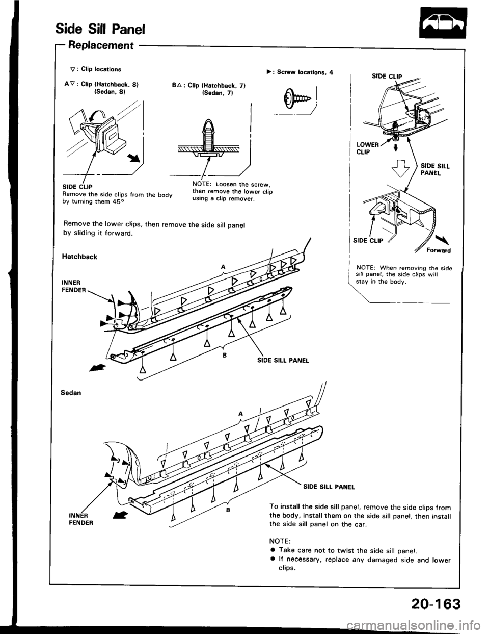
Side Sill Panel
Replacement
V : Clip locations
AV: Ctip {Harchbsck, 8){Sodan.
SIDE CLIPRemove the side clips fromby turning them 45o
Remove the lower clips,
by sliding it forward.
Hatchback
BA : Clip (Harchback, 7){sodan,7l
> : Screw locations, 4
q,
8l
/
rhe body
then remove the side sill panel
NOTE: Loosen the screw,then .emove the lower clipusing a clip remover.
NOTEj When removing the sidesill panel, lhe side clips will
\y':
SIDE SILL PANEL
To install the side sill panel, remove the side clips fromthe body, install them on the side sall panel, then instatlthe side sill panel on the car.
NOTE:
a Take care not to twist the side sill panet.
a lf necessary, replace any damaged side and lowerclips,
FENDER
20-163
Page 1033 of 1413
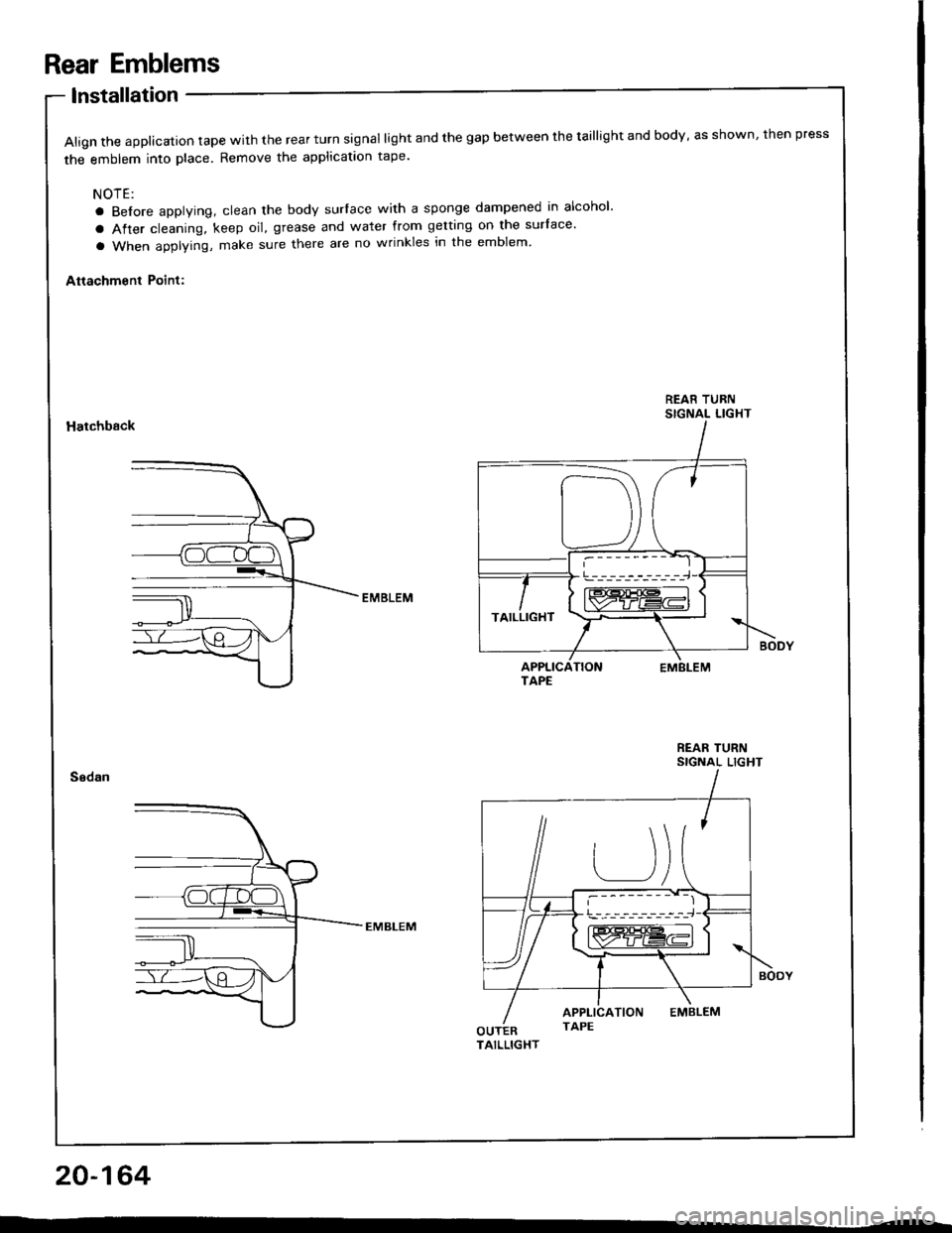
Rear Emblems
lnstallation
Align the applicalion tape with the rear turn signal light and the gap between the taillight and body, as shown, then press
the emblem into place. Remove the applicataon tape'
NOTE:
a Before applying, clean the body surlace with a sponge dampened in alcohol'
a After cleaning, keep oil, grease and water from getting on the surface'
a When applying, make sure there are no wrinkles in the emblem'
Attachment Point:
REAR TURNSIGNAL LIGHTHatchback
REAR TURNSIGNAL LIGHT
20-164
!---_-----------,-i-J
TAILLIGHT
Page 1034 of 1413
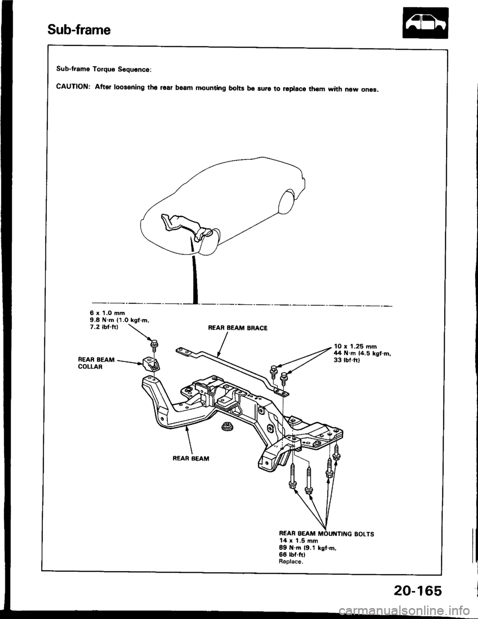
Sub-t.ame Torque Sequence:
cAUTloN: After roosening tho rsar beam mounting borts be sura to repraco thom with new onea.
6 x 'l.O mm9,8 N.m (1.0 kgt.rn,7.2 tbt-fllREAB BEAM BBACE
FEAR BEAMCOLLAR
10 x 1.25 mm44 N.m {4.5 kgt.m,33 rbr.ftl
REAR BEAM
REAR BEAM14 x 1.5 mm89 tt.m (9.1 kst.m,66 lbf.ftlBeplace.
Sub-frame
20-165
Page 1035 of 1413
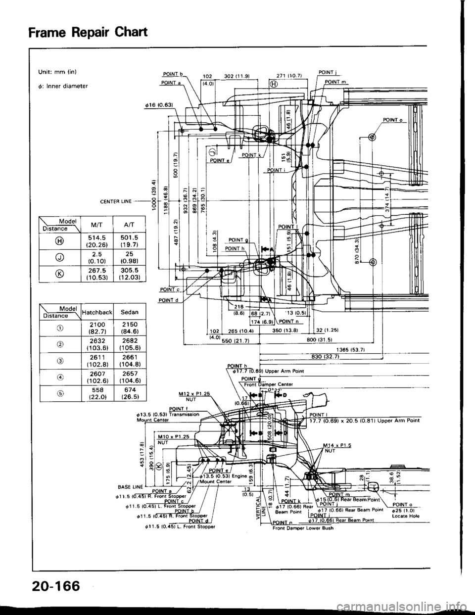
Frame Repair Ghart
1
ar"tr*,,,ua -!
BASE LINE
d11.5
dl 1.5 tO_
011.5
I cir (o-36;E;
y+, Aoad Poinr | 9rl lv
Front Osmpsr Lowsr Bush
20-166
cr1.5 (0.
ModelDls6ft-\M/T
@514.5
120.261
501 .5(19.7)
U-)2.5(0.10)25{o.98)
(J{10.53)112.03)
\---!e!s!SedanDistance \
o2100lE2.712150(84.6t
2632{103.6)
2642{105.6}
J5261 1(102.8)(104.8)
@2607(102.6)2657(104.6)
t22.Ol674(26.5)
Page 1036 of 1413
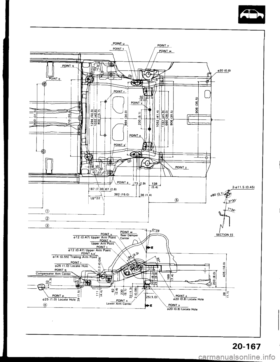
POINT w
d25 ll.ol Locare Hole g
@
20-167
Page 1037 of 1413
Heater and Air Conditioning
Heater ........ 21-1
Air Conditioning .......... ..22-1
SUPPLEMENTAL RESTRAINT SYSTEM {SRS}
The Integra SRS includes a driver's airbag, located in the steering wheel hub. In addition. all models except the
RS model for Canada have a front passenge.'s airbag located in the dashboard above the glovs box. Information
necessary to safely service the SRS is included in this Service Manual. ltems msrk€d with an asterisk (') on the
conlents page include, or are located near, SRS components. Servicing, disassembling or,eplacing thes€ items
will require special precautions and tools, and should therefore be done by an authorized Acura dealer.
a To avoid r6nd6dng tho SRS inoporativo. which could lead to personal injury or dealh in tho svont ot a sevele
frontal collision, all SRS servica work musl b€ portormed by an authorized Acura dealer.
a lmpropor sorvico procaduro3, including incorrect romoval and installatlon of tho SRS, could load to porsonal iniu-
ry causod by uninlonlional activation of tho ailbag8.
a All SRS eloctdcal widng harnossos are covored with yollow in3ulation. Relatsd compononts a.o locatod in tha
stsering column, flont console, daehboard, and dashboafd low6r pan6l, and in lhe dsshboa.d above lh€ glove
box. Do not uao electdcal tost equipmont on theae circuhs.
NOTE: The original radio has a coded theft protection circuit. Be sure to get the customer's code number beto.e
- disconnecting the battery.- removing the No. 32 (7.5 A) luse from the under-hood fuse/relay box.- removing the radio.
After service, reconnect power to the radio and turn it on. When the word "CODE" is displayed, enter the cus-
tomer's 5-digit code to restore radio operation.
Page 1038 of 1413
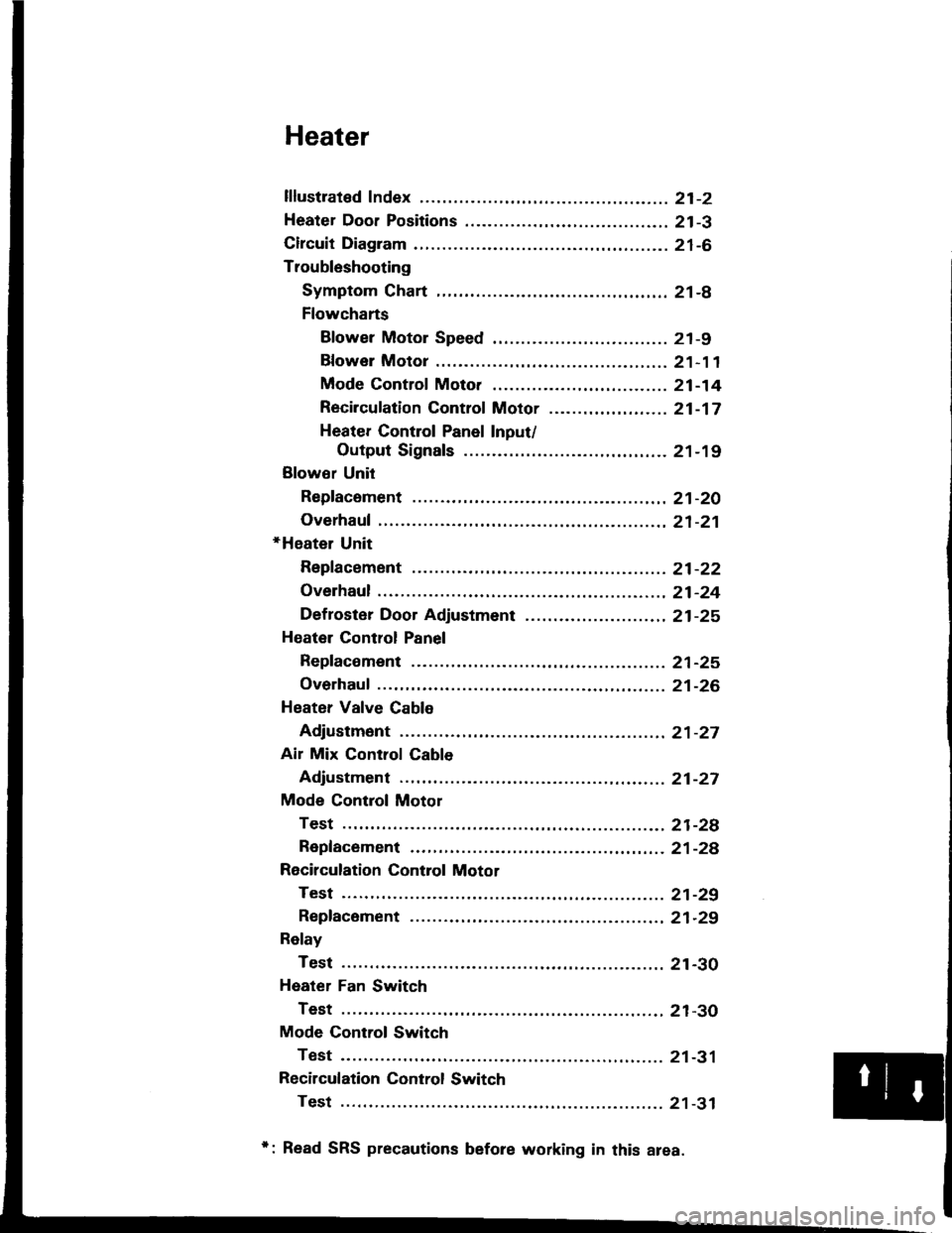
Heater
lflustrated Index ............. .........21-2
Heater Door Positions .........,..,. 21-3
Circuit Diagram ....................... 21-6
Troubleshooting
Symptom Chart ............. ......21-8
Flowcharts
Blower Motor Speed ............................... 21 -9
Bfower Motor .........,..,,,,,.. 21-11
Mode Control Moto. ............ ................... 21 -14
Recircufation Control Motor ......,...,.,,,.,.... 21 -17
Heater Control Panel Input/
Output Signals ..............21-19
Blower Unit
Repfacoment ....................... 21-20
Overhaul .......21-21
+Heater Unit
Repfacement ....................... 21-22
Overhaul .......21-24
Def roster Door Adjustment ...,............. ......,, 21 -25
Heatel Control Panel
Repfacoment ....................... 21-25
Overhaul .......21-26
Heater Valve Cable
Adjustment ...21-27
Air Mix Control Cable
Adjustment ... 21-27
Mode Control Motol
Test .............. ..................... 21-2e
Repfacement ..,..............,,,,.. 21-28
Recirculation Control Motor
Test .............. ..................... 21-29
Repfacement ....................... 21-29
Relay
Test .............. ..................... 21-30
Heater Fan Switch
Test .............. ..................... 21-30
Mode Control Switch
Test .............. ..................... 21-31
Recilculation Control Switch
Test .............. ..................... 21 -31
*: Read SRS precautions before working in this area.
Page 1039 of 1413
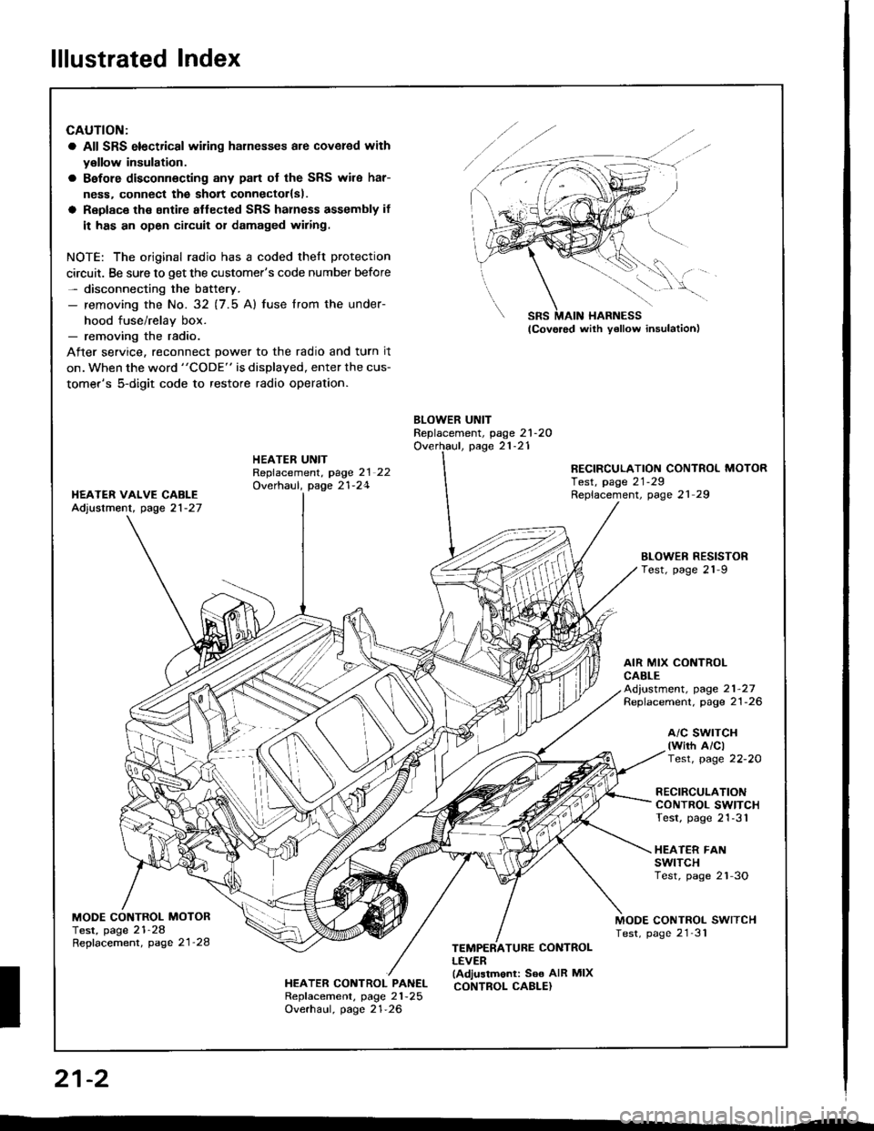
lllustrated Index
CAUTION:
a All SRS electrical wiling harnesses are covered with
y€llow insulation.
a Bafore disconnecting any pan of the SRS wile har-
ness. connect the sholt connectorlsl.
a Replace the sntire aflected SRS halness assembly if
it has an open circuit or damaged wiring.
NOTE: The original radio has a coded thelt protection
circuit. Be sure to get the customer's code number before- disconnecting the battery.- removing the No. 32 (7.5 Al fuse lrom the under-
hood fuse/relav box.- removing the radio.
After service, reconnect power to the radio and turn it
on. when the word "CODE" is displayed, enter the cus-
tomer's 5-digit code to restore radio operation.
BLOWER UNITReplacement, page 21-2OOverhaul, page 21-21HEATER UNITRepfacement, page 2l 22Overhaul, page 21-24
RECIRCULATION CONTROL MOTORTest, page 21-29Replacement, page 21 29I{EATER VAIVE CABLEAdjustment, page 21-27
BLOWEN RESISTORTest, page 21-9
AIR MIX CONTROLCABLEAd,ustment, page 21-27Replacement. page 21-26
a/c swrTcH(wirh A/clTest, page 22-20
RECIRCULATIONCONTROL SWITCHTest, page 21-31
HEATER FANswtTcHTest, page 2'l-3O
MODE CONTROL MOTORTest, page 21-28Repfacement, page 21'28
MODE CONTROL SWITCHTest, page 21'31
HEATER CONTROL PANELRepf acement, page 21 -25
Overhaul, page 21-26
TEMPERATURE CONTROLLEVER(Adjustmonl: See AIR MIXCONTROL CABLE}
SRS MAIN HARNESS
W,
21-2
I
Page 1040 of 1413
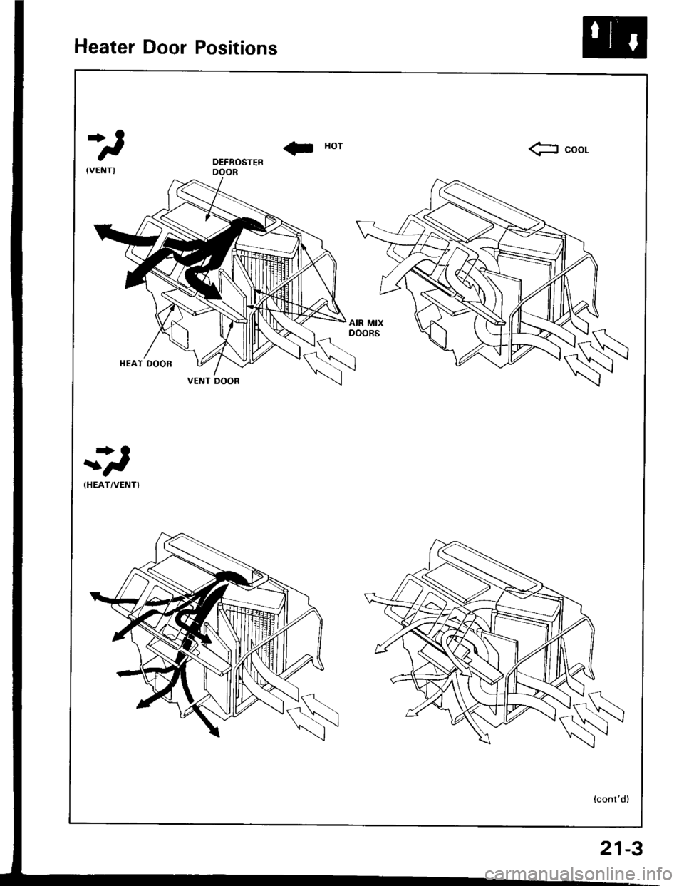
Heater Door Positions
*)
! xorfr coor.
-*)
(HEAT/VENTI
(cont'd)
VENT OOOR
21-3