connector or terminal HONDA INTEGRA 1994 4.G Workshop Manual
[x] Cancel search | Manufacturer: HONDA, Model Year: 1994, Model line: INTEGRA, Model: HONDA INTEGRA 1994 4.GPages: 1413, PDF Size: 37.94 MB
Page 1277 of 1413
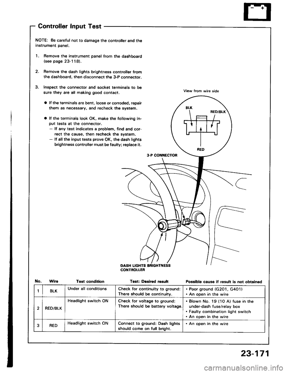
Controller Input Test
NOTE: 8e careful not to damage the controller and the
instrument panal.
1. Remove the instrument panel lrom the dsshboard
{see page 23-1181.
2. Remove the dash lights b.ightness controller {rom
the dashboard. then disconnect the 3-P connector.
Inspect the connector and socket terminals to be
sure they are all making good contact.
a lf the terminals are bent. loose o. corroded, repsir
them as necessary, and recheck the system.
a It the terminals look OK, make the tollowing in-
Dut tests at the connector.- lf any test indicates a problem, find and cor-
rect the cause, then recheck the system.- lf all the input tests prove OK, the dash lights
brightness controller must be faulty; replace it.
View from whe side
Possible causo it resull is not obtained
3-P CON[{ECTOR
OASH LIGHTSCOI{TROLIER
WireTost conditionTogt: Dasired resuh
1BLKUnder all conditionsCheck for continuity to ground:
There should be continuitv.
. Poor ground (G20 l , G4O1). An open in the wire
RED/BLK
Headlight switch ONCheck Jor voltage to ground:
There should be battery voltage.
Blown No. 19 (1O A) tuse in the
under-dash fuse/relay box
Faulty combination light switch
An open in the wire
aREDHeadlight switch ONConnect to ground: Dash lights
should come on full bright.
. An open in the wire
23-171
Page 1280 of 1413
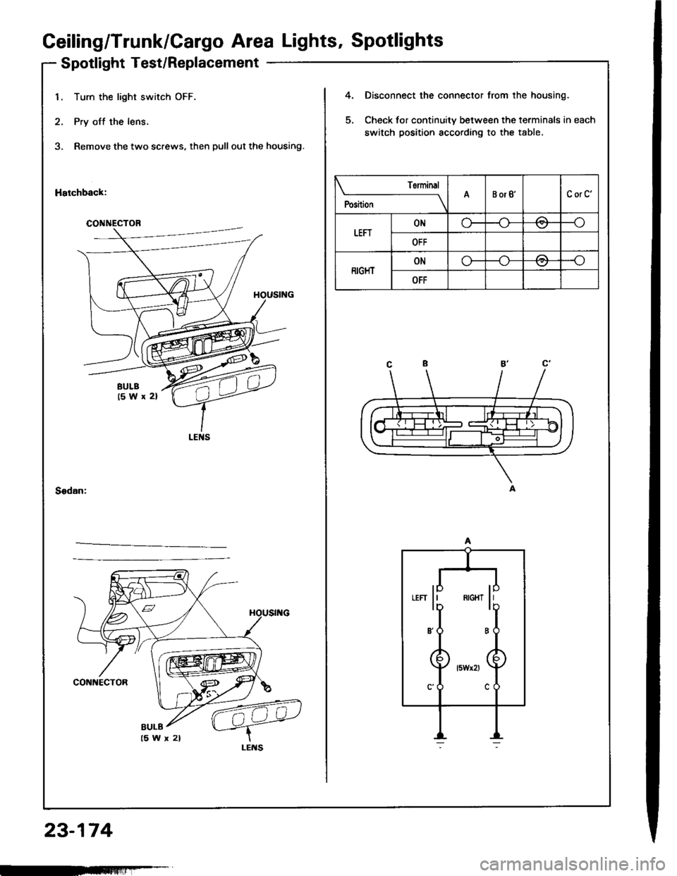
Ceiling/Trunk/Cargo Area Lights, Spotlights
Spotlight Test/Replacement
23-174
1. Turn the light switch OFF.
2. Pry off the lens.
3, Remove the two screws, then pull out the housing.
Hatchback:
4.
5.
Disconnect the connector from the housing.
Check for continuity between the terminals in each
switch position according to the table.
Sedan:
CONNECTOR
Torminal
;r,,-
----lABorB'CorC'
tEFrONo-/:\--o\:/
OFF
RIGHTONo---o
OFF
"" li ** li
B'O B
BULB
-FFmlliF-T
Page 1281 of 1413
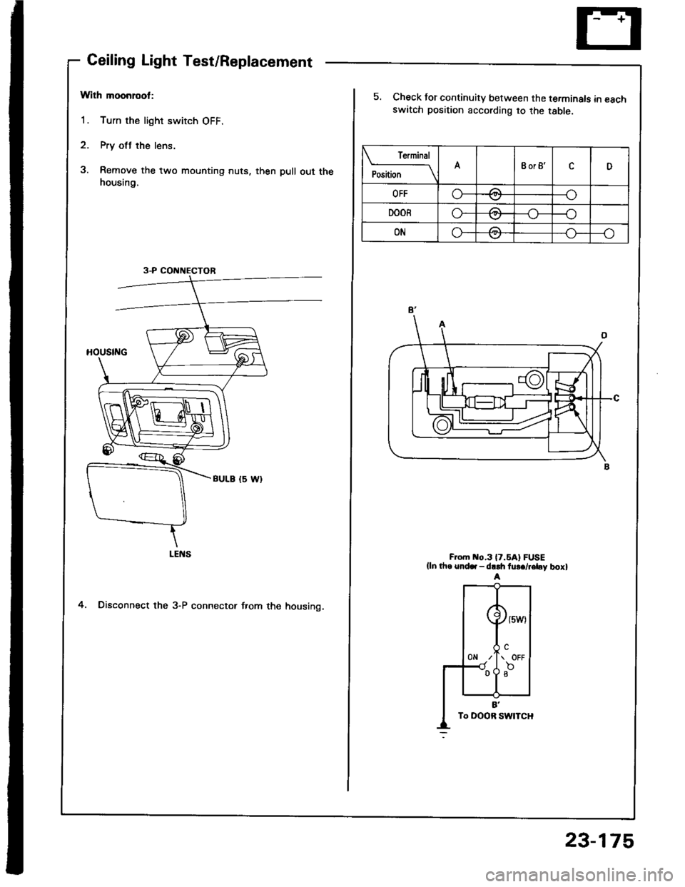
Ceiling Light Test/Replacement
With moonrool:
1. Turn the light switch OFF.
2. Pry otJ the lens.
3. Remove the two mounting nuts, then pull out thehousing.
4. Disconnect the 3-P connector f.om the housing.
3-P CONNECTOR
re.mrnal
Position \A8or8'cD
OFFo-za--o\7
DOORo---o\7
ONG-/1--o\:.,/
5. Check for continuity between the terminals in €schswatch position according to the table.
F om o.3l7.5Al FUSE(ln th. snd.. - dr.h fu!./r€by boxl
23-175
Page 1282 of 1413
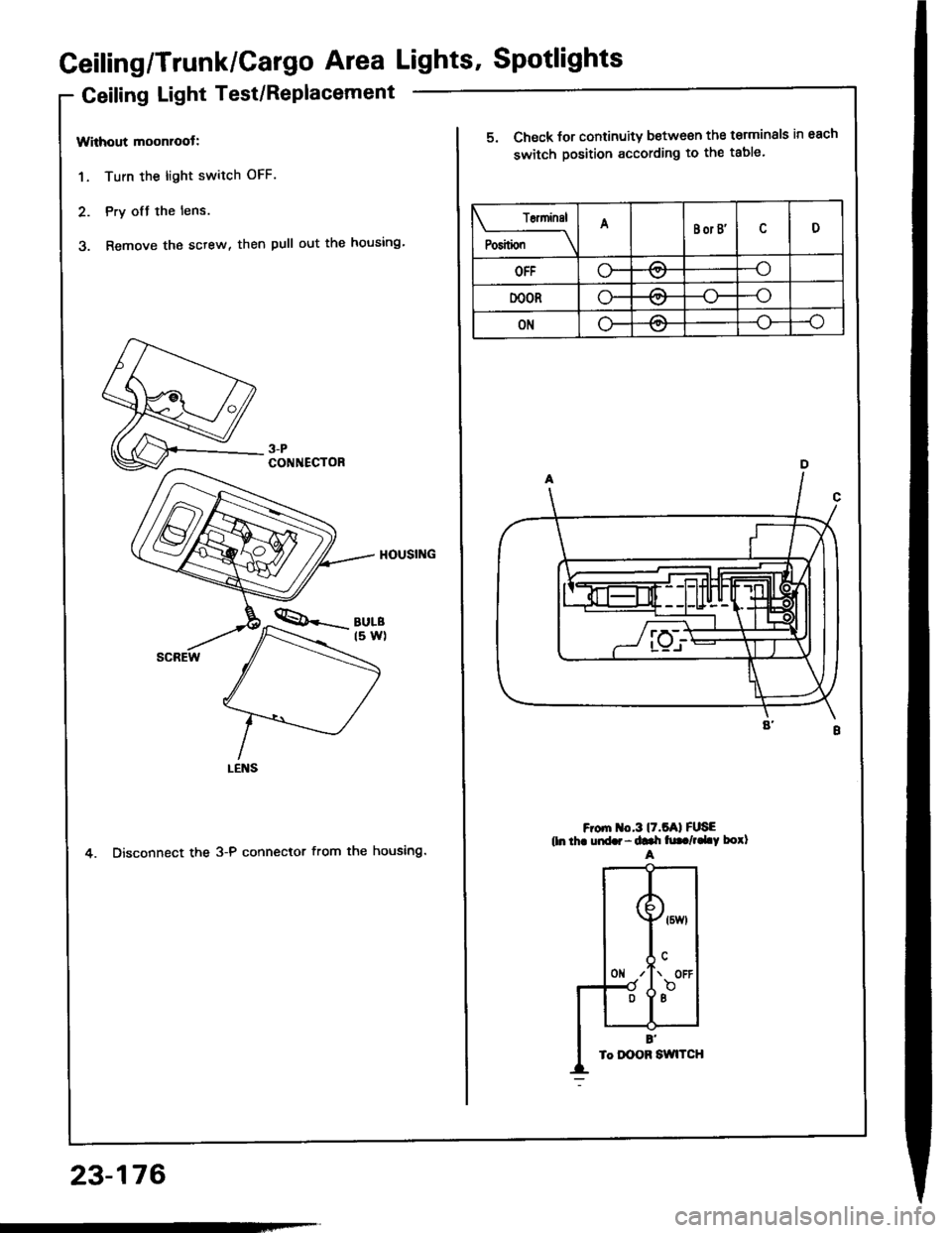
Geiling/Trunk/Cargo Area Lights' Spotlights
Geiling Light Test/Replacement
Without moonroot:
1. Turn the light switch OFF.
2. Pry ofJ the lens.
3. Remove the sctew, then pull out the housing'
4. Disconnect the 3-P connector from the housing.
3-PCONNECTOR
23-176
T6ninsl
P"riti"" \
ABor B'D
OFFo-/:\--o\:.,/
DOORo-A--o
ONLF/A--o
5. Check for continuity between the terminals in each
switch position according to the table.
F om o.3l7.5Al FUSEtln thr uid.r - ddr h|. /,.LY borlA
Page 1284 of 1413
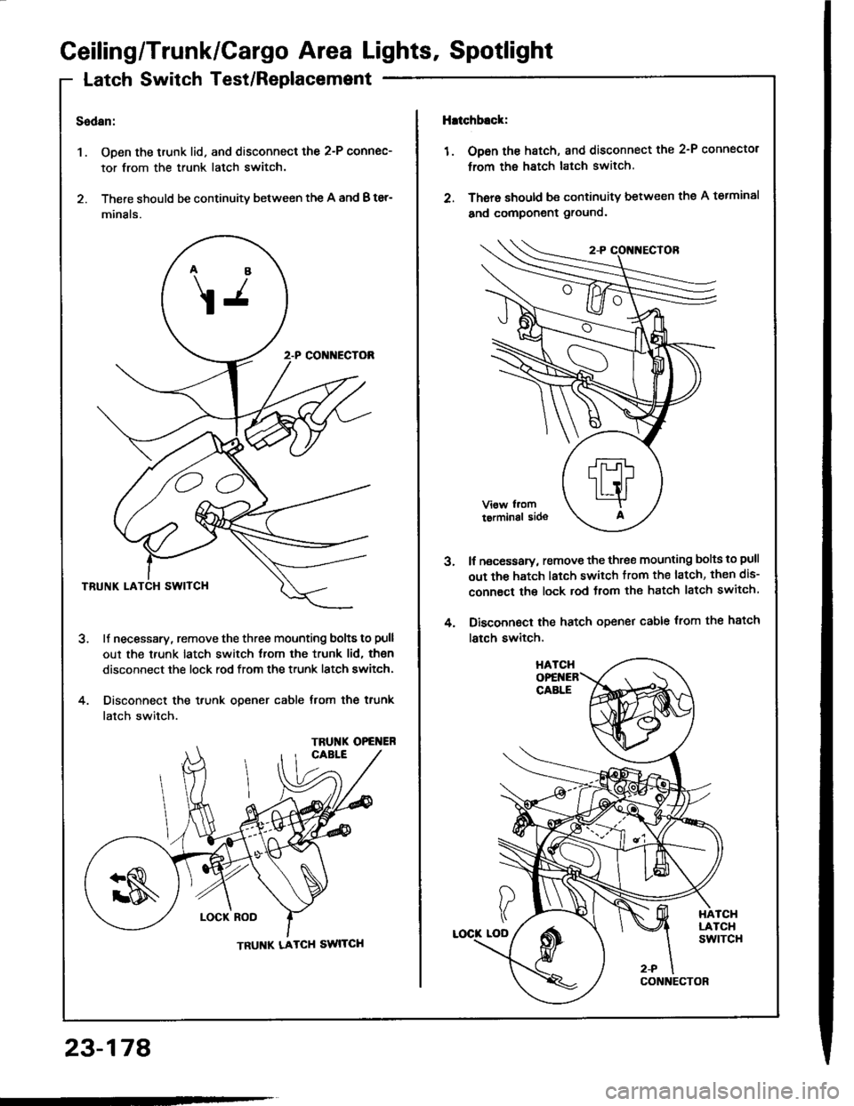
Ceiling/Trunk/Cargo Area Lights, Spotlight
Latch Switch Test/Replacemsnt
Sedan:
1. Open the trunk lid. and disconnect the 2-P connec-
tor from the trunk latch switch.
2. There should be continuity between the A and B ter-
minals.
ll necessary, remove the three mounting bolts to pull
out the trunk latch switch from the trunk lid, then
disconnect the lock rod from the trunk latch switch.
Disconnect the trunk opener cable from the trunk
latch switch.
4.
\j
CC
TRU'{K OPG ER
TRUNK LATCH SWITCH
lhtchb.ck:
1 . Op6n the hatch, and disconnect the 2-P connector
trom the hatch latch switch.
2. There should be continuity between thg A terminal
and component ground.
lf necessary, remove the three mounting bolts to pull
out the hatch latch switch trom the latch, then dis-
connact the lock rod Jrom the hatch latch switch
Disconnect the hatch opener cable trom the hatch
latch switch,
3.
4.
23-178
Page 1286 of 1413
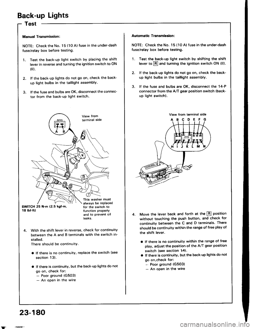
Back-up Lights
Manual Transmigsion:
NOTE: Check the No. 1 5 { 1 O A) fuse in the under-dash
fuse/relay box befote testing.
'1. Test the back-up light switch by placing the shift
lever in reverse and turning the ignition switch to ON
(
).
2. It the back-up lights do not go on, check the back-
up light bulbs in the taillight assembly.
3. lf the tuse and bulbs are OK. disconnect the connec-
tor from the back-up light switch.
terminal sade
This washer must
always be replacedtor the switch tolunction properlY
and to ptevent ollteaKs.
4. With the shift lever in reverse. check Jor continuity
between the A and B terminals with the switch in-
stalled.
There should be continuity.
a lf there is no continuity, replace the switch {see
section 13).
a lf there is continuity, but the back-up lights do not
go on, check for:- Poor ground (G5O3)
- An open in the wire
23-180
Automatic Transmission:
NOTE: Check the No. l 5 ( 1 O A) fuse in the under-dash
fuse/relay box belore testing.
1. Test the back-up light switch by shitting the shift
lever to l3l and turning the ignition switch ON (ll).
2. lf the back-up lights do not go on, check the back-
up light bulbs in the taillight assembly.
3. lf the tuse and bulbs are OK, disconnect the 14-P
connector from the A/T gear position switch (back-
up light switch).
Move the lever back and torth at the LBI position
without touching the push button, and check tor
continuitv between th€ C and D terminals. There
should be continuitY within the range of free plsy of
the shift lever.
a lf there is no continuity within the range oJ J.ee
play, adjust the position ot the A/T gear position
switch lsee section 141.
a lt there is continuity, but the back-up lights do not
go on,check {or:- Poor ground {G503)- An oDen in the wire
4.
Page 1288 of 1413
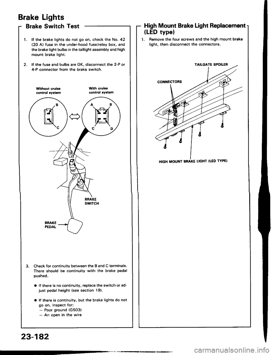
AB'|Frt
jr'li
CD
Brake Lights
Brake Switch Test
lf the brake lights do not go on, check the No. 42
{2O A) fuse in the under-hood fuse/relay box, and
the brake light bulbs in the taillighr assembly and high
mount brake light.
lf the fuse and bulbs are OK. disconnect the 2-P or
4-P connector {rom the brake switch.
3. Check fo. continuitv between the B and C terminals.
There should be continuity with the brake pedal
pushed.
a lJ there is no continuitv, replsce the switch or ad-
just pedal height {see section 19).
a lf there is continuity, but the brake lights do not
go on, inspect for:- Poor ground (G5O3)
- An ooen in the wire
High Mount Brake Light Replacement
(LED typel
1. Remove the four screws and the high mount btake
light, then disconnect the connectors.
HIGH ltlOUt{T BRAKE LIGHT {LED TYPEI
23-1A2
Page 1292 of 1413
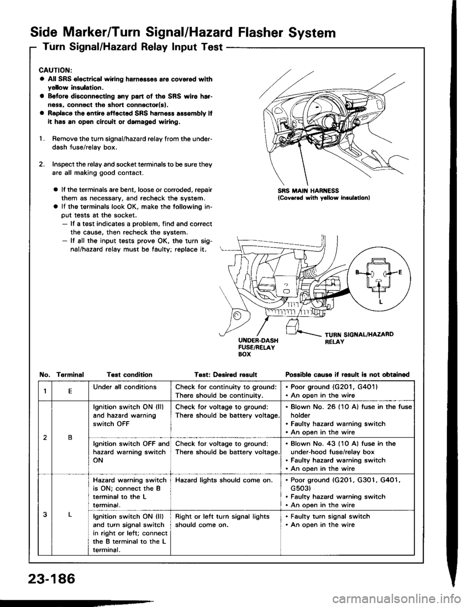
Side Marker/Turn Signal/Hazard Flasher System
Turn Signal/Hazard Relay Input Test
CAUTION:
a All SRS electrical wiring harn6ss6s ar€ covered with
yellow insulation.
a B€foro disconn6cting any part of th€ SRS wire har-
noss, connoct tho short connector(s).
a Replaco tho ontiro sftoctod SRS harness ass€mbly it
it has an open circuit or damagod wiring,
I . Remove the turn signal/hazard relay from ths under-
dash Juse/relay box.
2. Inspect the relay and socket terminals to be sure they
are all making good contact.
a It the terminals are bent, loose or coroded, repair
them as necessary, and recheck the system.
a lf the terminals look OK, make the tollowing in-
put tests at the socket.- lf a test indicates a problem, find and correct
the cause, then recheck the system.- lf all the input tests prove OK, the turn sig-
nal/hazard relay must be taulty; replace it.
UI{DEB-DASHFUSE/RELAYBOX
Test: D€sired rosult
SBS MAIN HAR ESS{Covg.ed with yollow inrulltion)
TelminalTeEt conditionPo$iblo causo it fosult is not obtainod
,lEUnder all conditionsCheck for continuity to ground:
There should be continuitv.
. Poor ground (G201 , G4O1). An oDen in the wire
2B
lgnition switch ON (ll)
and hazard warning
switch OFF
Check for voltage to ground:
There should be battery voltage.
Blown No. 26 (10 A) fuse in ths fuse
holder
Faulty hazard warning switch
An open in the wire
lgnition switch OFF and
hazard warning switch
ON
Check for voltage to ground:
There should be battery voltage.
Blown No. 43 (10 Al fuse in the
under-hood fuse/relay box
Faulty hazard warning switch
An ooen in the wire
3
Hazard wa.ning switch
is ON; connect the B
terminal to the L
termrnat.
Hazard lights should come on.Poor ground (G2O1, G3O1, G4O1
G503)
Faulty hazard warning switch
An open in the wire
lgnition switch ON (lll
and turn signal switch
in right or left; connect
the B terminal to the L
terminal.
Right or left turn signal lights
should come on.
. Faulty turn signal switch. An open in the wire
23-186
-
Page 1293 of 1413
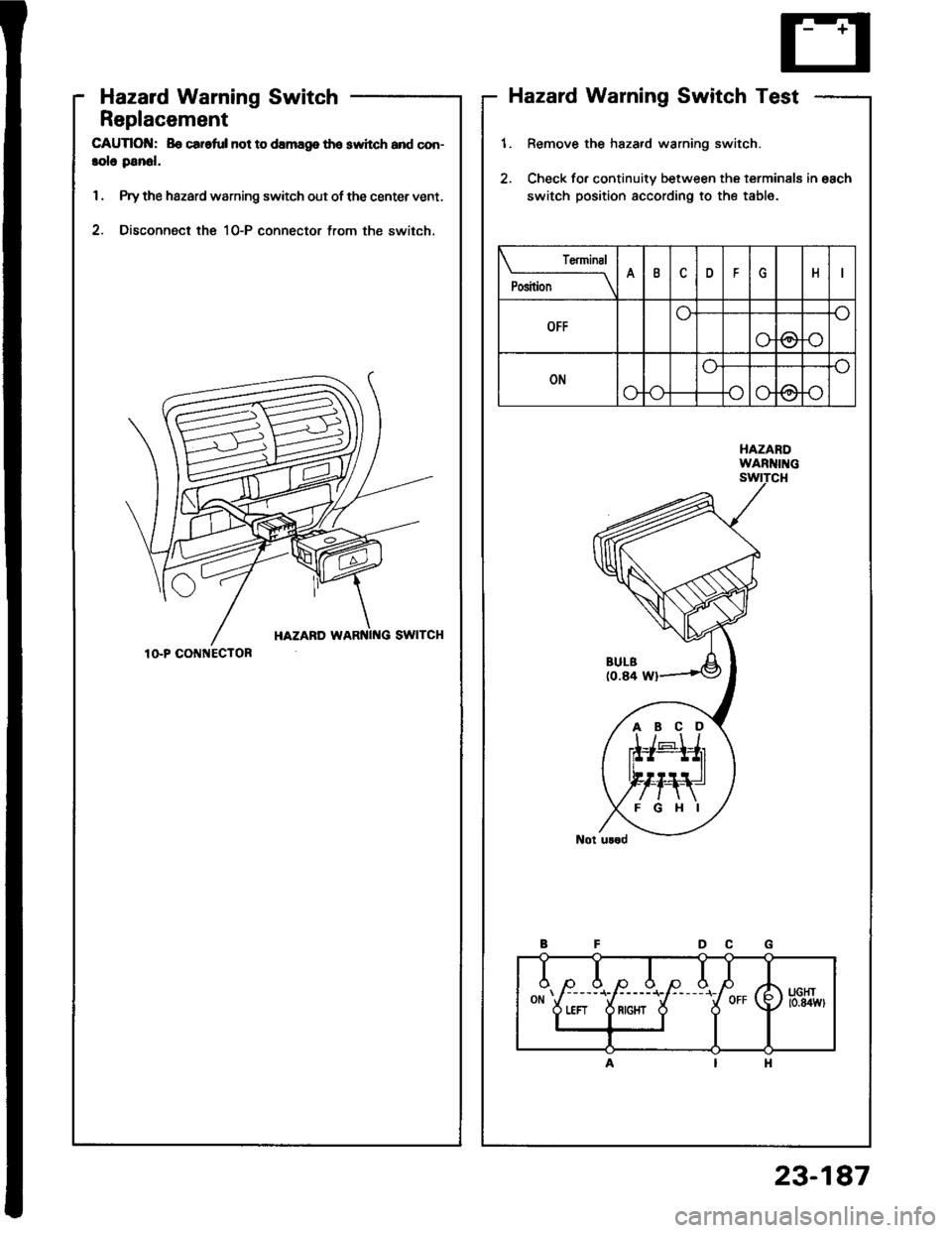
Hazard Warning Switch
Replacement
CAUTIOI{: Bo car.ful not to damag8 tho switch and con-
lolo panol.
1. Prythe hazard warning switch out of the center vent,
2. Disconnect the 10-P connector trom the switch.
Hazard Warning Switch Test
1.
2.
Remove the hszard warning switch.
Check fo. continuity between the terminals in each
switch position according to the table.
uorr) to.uwl
I"j'!ld
PositionAIDFH
OFF
@r)
ONo
@
ABCD
10-P CO ECTOR
23-187
Page 1294 of 1413
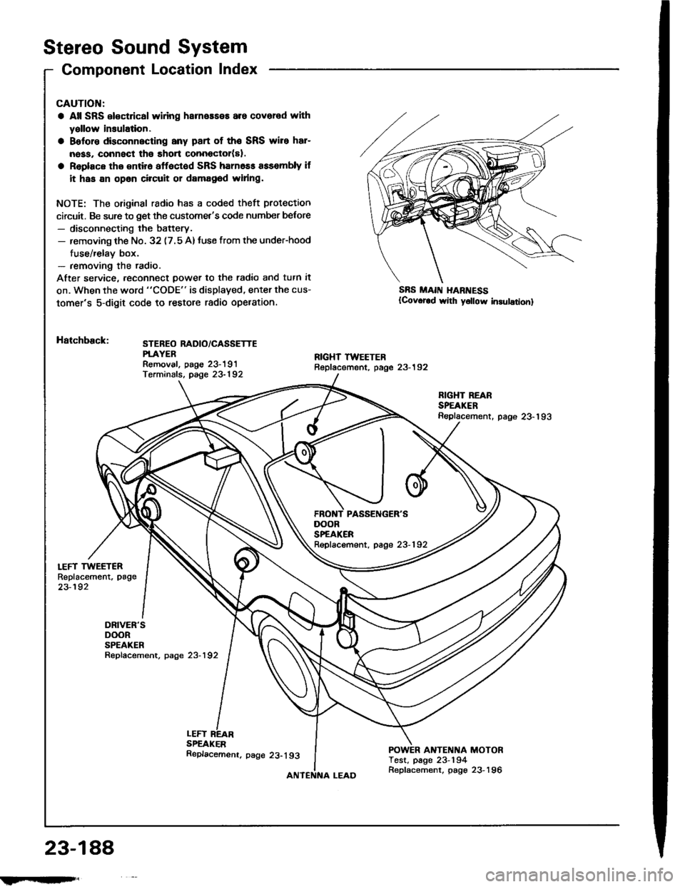
Stereo Sound System
Component Location Index
LEFT TWEETERReplacement, page
23-192
DRIVER'SDOORSPEAKERRepfacement, page 23-192
CAUTION:
a All SRS el€ctrical wlring harneaseE are covered with
yallow insulation.
a Belore dbconnscting any part of the SRS wire har-
nass, connect tho short connector(sl.
a Replace tho entir6 affoctod SRS harn6ss assembly if
it has an opan circuit or damag6d widng.
NOTE: The original radio has a coded theft protection
circuit. Be sure to get the customet's code number belore- disconnecting the battery.- removing th€ No. 32 (7.5 A)tuse from the under-hood
fuse/relay box.- removing the radio.
After service, reconn€ct power to th€ radio and tutn it
on. When the word "CODE" is displaved, enter the cus-
tomer's 5-digit code to restore radio opelation.
Hatchback:STEBEO RADIO/CASSETTEPTAYERRemoval. paoe 23-191Terminals, page 23-192
SBS MAII{ I{ARI{ESS(Covor€d wirh y6llow in3ulationl
LEFTSPEAKER
RIGHT REARSPEAKERReplacement. page 23-193
ANTENNA MOTORTest, page 23-194
DOORSPEAKERRepfacement, page 23-192
23-188
!iltil;s'
Replacemenr. page 23-193
Replacement, page 23-196