connector or terminal HONDA INTEGRA 1994 4.G Workshop Manual
[x] Cancel search | Manufacturer: HONDA, Model Year: 1994, Model line: INTEGRA, Model: HONDA INTEGRA 1994 4.GPages: 1413, PDF Size: 37.94 MB
Page 1387 of 1413
Supplemental Restraint System (SRSI
Troubleshooting (cont'dl
SRS Indicator Light Stays on Continuously
NOTE: Before troubleshooting, make sure that battery
voltage is 12 V or mo.e. Otherwise you'll obtain wrong
test readings.
1. Make a photocopy of the chart on page 23-283,
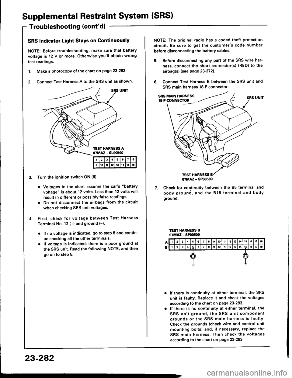
2. Connect Test Harness A to the SRS unit as shown.
Tu.n the ignition switch ON (lll.
. Voltages in the chart assume the car's "battery
voltage" is about 12 volts. Less than 12 volts will
result in different or possibly talse readings.
. Do not disconnect the airbags ftom the circuit
when checking SRS unit voltages.
First, check for voltage between Test Harnoss
Terminal No. 12 (+) and ground (-).
. lf no voltage is indicated, go to step I and contin-
ue checking all the other terminals.
o lf vottsge is indicated, there is a poor ground at
the SRS unit. Read the following NOTE, and then
go on to step 5.
I21I
tolll2t3tlrt
23-282
TEST HANNESS
NOTE: The original .adio has a coded theft protection
circuit. Be sure to get the customer's code number
before disconnecting the battery cables.
Before disconnecting any pan of the SRS wire har-
ness, connect the short connecto(s) {RED) to the
airbag(s) (see page 23-2721.
Connect Test Harness B between the SRS unit and
SRS main harn€ss 18-P connector.
7. Check for continuitv between the 85 terminal and
body ground, and the Bl5 terminal and body
ground.
TEST HARNESS B07MAZ - SPqrS{X)
lf there is continuity at either terminal, the SRS
unit is faulty. Replace it and check the voltages
according to the chan on page 23-283.
lf there is no continuity at either terminal, the
SRS unit ground, the SRS unit component
grounds or the SRS main harness is faulty
Check the grounds (check wire and control unit
mounting bolts) and, if necessary, replace th€
SRS main harness. Then check the voltages
according to the chart on page 23-283
Page 1388 of 1413
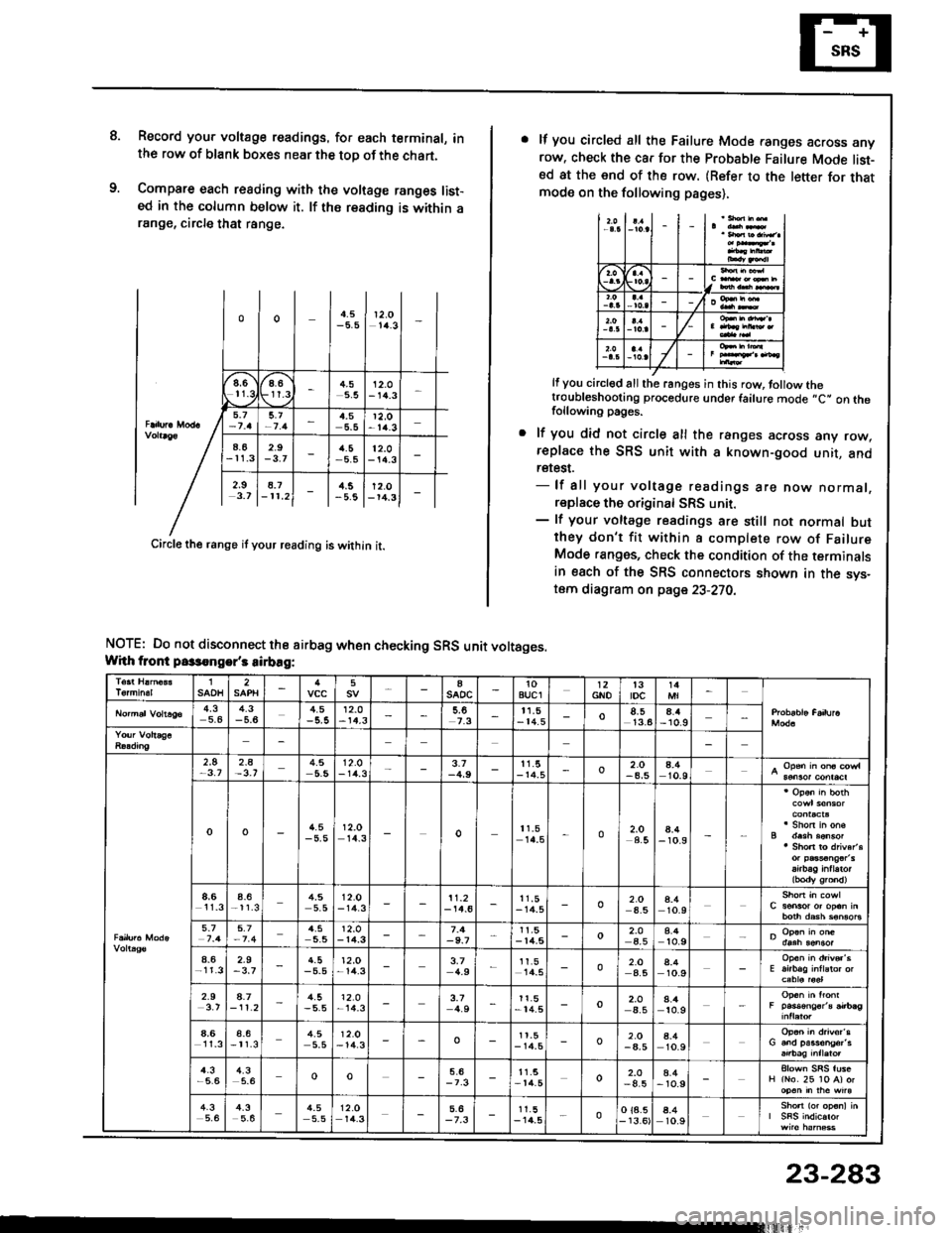
8.Record you. voltage readings. for each terminal, inthe row of blank boxes near the top of the chart.
Compare each reading with the voltage ranges list-ed in the column below it. lf ths reading is within arange, circle that range.
oo4.512,O1/4.3
".)6r-
at'9
t.g4.55.512.O- 14.3
5.t4,5r2,o-t4.3
4.62.9rl.5-5.512.0- 14.3
2.9 18.7 | l..s lr2.ol3.7 l-rr.2l - | -5.8 l-ra.3l -
Circle the range if your reading is within it.
NOTE: Do not disconnect the airbag when checking SRS unit voltages.Whh tront passongor's sirbag:
lf you circled all the Failure Mode ranges across anyrow. check the car for the Probable Failure Mode list-sd at the end of the row. (Refer to the letter for thatmode on the following pages),
I
/
It you circl€d all the ranges in this row, tollow thetroubleshooting procedure under failure mode ,,C" on thefollowing pages.
lf you did not circle all the ranges across any row,replace the SRS unit with 8 known-good unit, andretest.- lf all your voltage readings are now normal,replace the original SRS unit.- lf your voltage readings are still not normal butthey don't fit within a complete row of FailureMode ranges, check the condition of the terminalsin esch of the SRS connectors shown in the svs-tom diagram on page 23-270,
1SAOH25aSADC10auclGNOt3tDc4,35.44.3-5.64.512.0-14.3t1,5- 14.5o13.64.4- 10.9
2.5-3.72_A4.512.O- 1rt.33.1-4,911.5- r4.5o2.O-4,54.410.9
oo4.5-5,512.014_3o11.514.5o2.O4.58.4- 10.9
8,6l1_3a_6-11.34,55.512.0- 14.311.2-14.611.5- 14.5o2.O4.54.410.9
5_74.512.0- 14.3-9.7r1,5-14,5o2.O4.58.4to.9
4.62.9-3,74.5-5.512,O-14.33,74.9I1.5l4_502.O4.58.410.9
2.94.7- 11 .24.5-5.5'12.o-14.33.74.911.5- 14.5o2.Oa_54.410.9
4,6l1_3a_6-t1.34.55.512.O-14.3oI t.5- r4.5o2.O-4,54.410.9
4.3-5,64.35.6oo11.5- t lt.5o2.O-4.54.4- 1o.9
4.35,64_35.64.55.512.Or4.3-7.31 1.5- 14.5oo 18.5- 13.64.410.9
23-283
Page 1389 of 1413
Supplemental Restraint System (SRSI
Troubleshooting (cont'd)
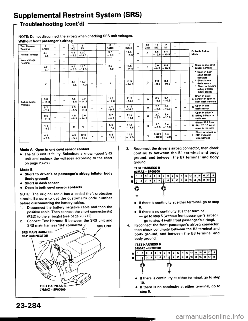
NOTE: Do not disconnect the airbag when checking SRS unit voltages.
Without lront Passongor's sirbag:
Modo A: Open in one cowl sonsor conlact
r The SRS unit is faultY. Substitute a known-good SRS
unit and recheck the voltages according to the chart
on page 23-283.
Mods B:
. Short to driver's or Passonger's aitbag inflator body
(body groundl
. Short in dash sonsor
. Opsn in both cowl sgnsor contacts
NOTE: The original radio has a coded theft protection
circuit. Be sure to get the customer's code number
before disconnecting the battery cables.
1. Disconnect the battery negative cable and then the
positive cable. Then connect the short connectots(s)
(RED) to the airbag(s) (see page 23-272).
2. Connect Test Harness B between the SRS unit and
A
B
SRS main harness 18-P connector.SRS UN]T'...SRS MAIN HARNESS18.P CONNECTOR
3. Reconnect the driv€r's airbag connector, then check
continuity between the B1 terminal and body
ground, and b€twesn the 87 terminsl and body
grounq,
TEST HABT{ESS B
. lf there is continuity at either terminal, go to step
o.
. lf there is no continuity at sither terminal'
- go to step 5 (without front passonge/s airbag)'
- go to step il (with front passenger's airbag)'
Reconnect the front passonger's sirbag connector,
then check continuity betwo€n ihs 82 t€rminal and
body ground, and between the 88 terminal and
body ground.
lf there is continuity at either terminal, go to step
10.
lf there is no continuity at either terminal, go to
step 5.
lSAOHvcc58saoc10BUCI12Gto13toct4
4,35.65.512.O- 14.35,6-7.311.5- 14,5oa_5-13.68.:aro.9
2.43.74.55.5
't2.o
14.33.74.911,5-14.5o2.O-8.58.4-r0.9
o4.55,512.O- 14.3o11.5-14,5o2.O-8.58./a-r0.9
4.6-11.3-5.512.O- 14.311.2- 14.611.514,5o2.O8./t-r0.9
5.74.5t2.o14,3-9.7tt.5- 14_5o-8.58.1-10.9
4.611.34.5- 5.512.0- 14.33.7-4.91t.514.5o2.O-8.5a.a-r0.9
4.3oo5,6-7.311.514,5o2,O8.it,r0.9H ll{o. 26 lo Al o.
4.3-5.64.5-5.512.O- 14.3-7.3t1.5- 14-5oo ta,5- 13.0tE,4-10.9
23-284
Page 1390 of 1413
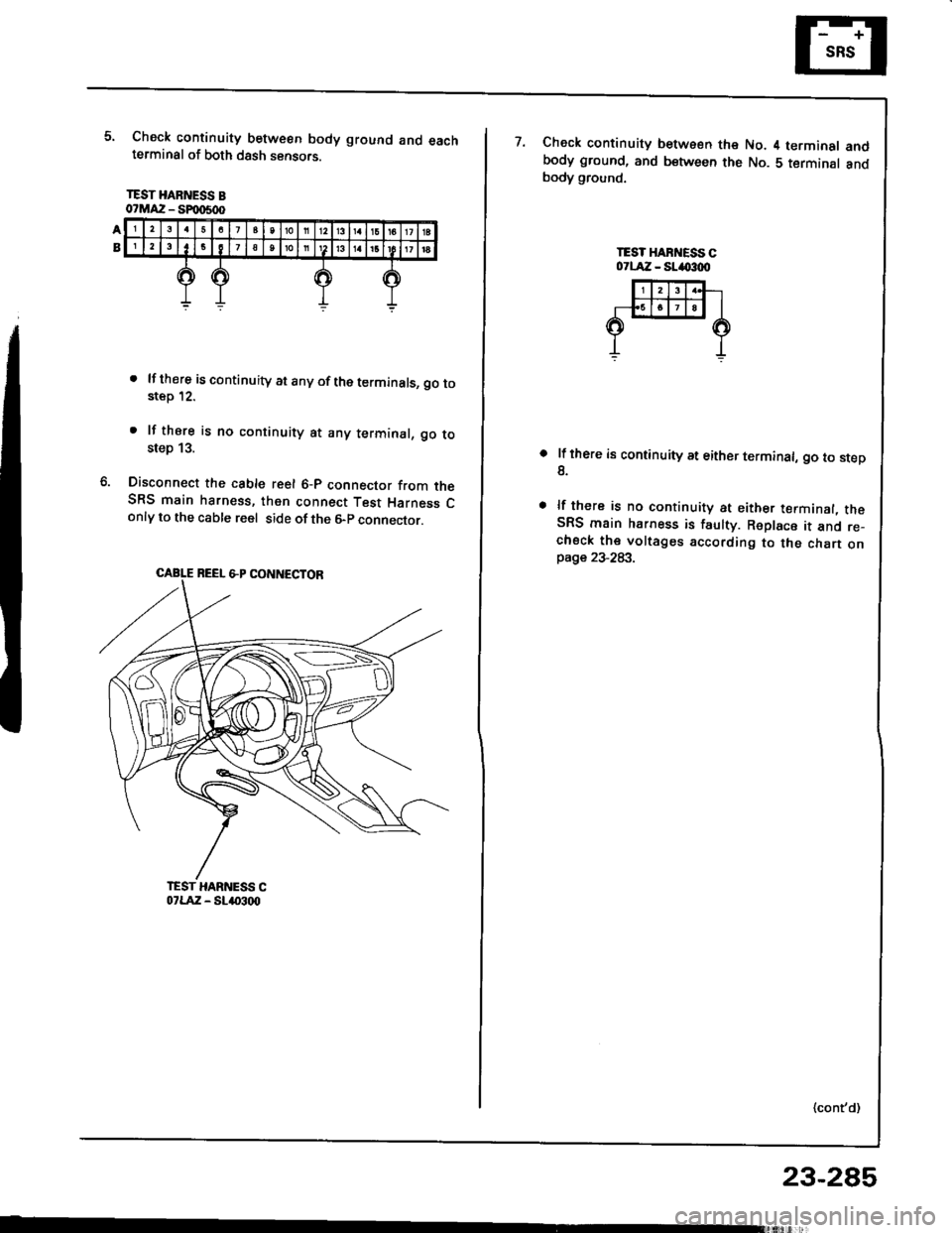
Check continuity between body ground and eachterminal of both dssh sensors.
TEST HARNESS Bo?MAZ - SFmSd)
. lf there iscontinuity at anyof theterminals, go tostep 12.
. lf thsre is no continuity at any terminal, go tosteo 13.
Disconnect the cable reel 6-p connector from theSRS main harn€ss, then connect Test Harness Conly to the cable reel side of the 6-p connector.
CABLE NEEL &P CONNECTOR
7.Check continuity between the No. 4 terminal andbody ground, and between the No. 5 terminal andbody ground.
TEST HABI{ESS C07LAiZ - SLIO:loo
lf there is continuity at either terminal, go to step8.
lf there is no continuity at either terminal, theSRS main harness is faulty. Replace it and re_chsck the voltages according to the chart onpage 23-283.
(cont'd)
23-285
Page 1391 of 1413
Supplemental Restraint System (SRS)
Troubleshooting {cont'd}
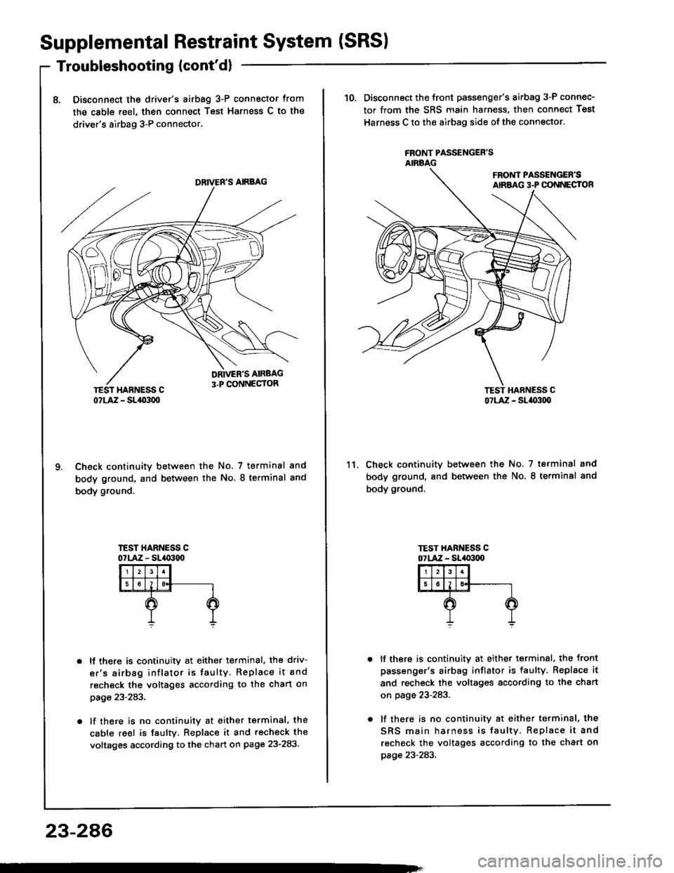
8. Disconnect the drive/s airbag 3-P connector trom
the cable reel, then connect Test Harness C to the
driver's airbag 3-P connector.
Check continuitv between the No. 7 terminal and
body ground, and between the No. 8 terminal and
body ground.
lJ there is continuity at either terminal, the driv-
er's airbag inflator is faulty. Replace it and
recheck the voltages according to the chart on
page z3- z6J.
lf there is no continuity at either terminal, the
cable reel is faulty. Replace it and recheck the
voltages according to the chart on page 23-283.
DRIVER'S AIRBAG
23-286
10. Disconnect the front passenger's airbag 3-P connec-
tor from the SRS main harness, then connect Test
Harness C to the airbag side of the connector.
FRONT PASSENGER'SANBAG
Check continuitv between the No. 7 terminal and
body ground, and between the No. 8 te.minal and
body ground.
lf there is continuitv at either terminal, the Jront
passenger's airbag inflator is faulty. Replace it
and recheck the voltages according to the chart
on page 23-283.
lf there is no continuitv at either terminal, the
SRS main harness is faulty. Replace it and
recheck the voltages according to the chart on
page 23-283.
11.
o7LAiZ - Slao:tq,
Page 1392 of 1413
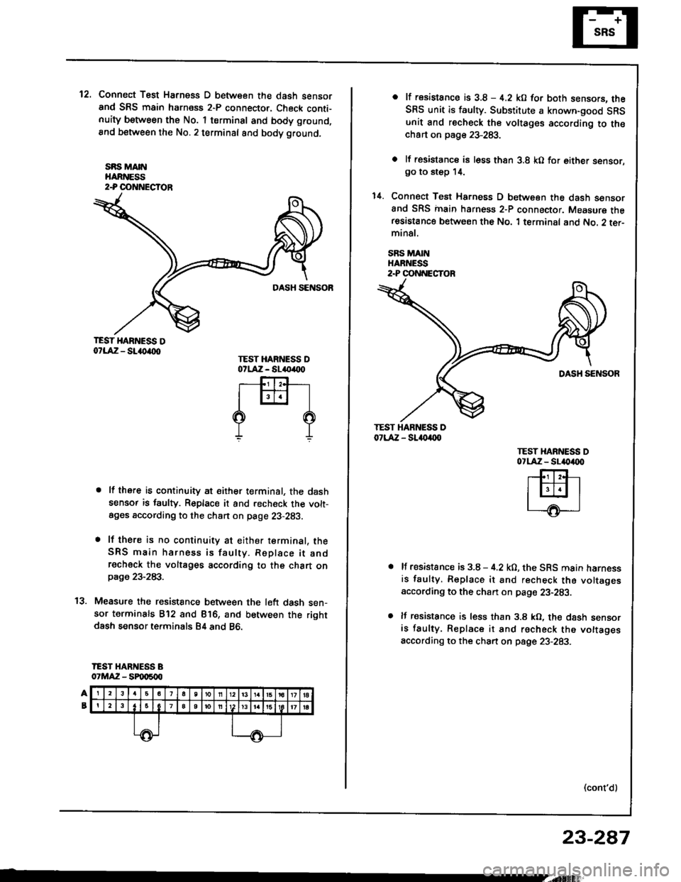
12.Connect Test Harness D between the dash sensorand SRS main harness 2-P connector. Check conti-nuity between the No. 1 terminsl and body ground,
8nd between the No.2 terminal and body ground,
sRs MA[{HARNESS2-P OOTTNECTOR
TEST HARNESS Do?LAiZ - SL()a(xt
. lf there is continuity at either terminal, the dashsensor is faulty. Replace it and recheck the volt-ages according to the chan on page 23-293.
. lf there is no continuity at either terminal, theSRS main harness is faulty. Replace it andrecheck the voltages according to the chart onpage 23-283.
Measure the resistance between the l6ft dash sen-sor terminals B'12 and Bl6, and between the rightdash sensor terminals B4 and 86.
IEST HARNESS B07MAZ - SPqt500
TEST HARNESS DotlA:z - sl(,(x)
rffi-l
??
t'l
o lt rssistance is 3.8 - 4.2 kO for both sensors. theSRS unit is faulty. Substitute a known-good SRSunit €nd recheck the voltages according to th€chart on page 23-283.
o lf resistancs is l6ss thsn 3.8 kO for either sensor.go to step 14.
1il. Connect Test Harness D between the dash sensorand SRS inain harness 2-P connector. Measure theresastance between the No. 1 terminal and No. 2 ter-minal.
SRS MAINHARNESS2.P CONNECTOR
TEST HAR ESS D07LAZ - SL.{)a(xl
TEST XARNESS DotlA:z - sl4|)4tx)
lf resistance is 3.8 - 4.2 kO, the SRS main harnessis faulty. Replace it and recheck the voltagesaccording to the chan on pag€ 23-283.
lf resistance is less than 3.8 kO, the dash sensoris faulty. Replace it and recheck the vottagesaccording to the chart on psge 23-283.
(cont'd)
23-287
Page 1393 of 1413
Supplemental Restraint System (SRS)
Troubleshooting (cont'd)
Modg C: Shon in one cowl son3ol, or open in both dash
sensors
Mode D: Open in ono da3h sensol
NOTE: The original radio has a coded theft protection
circuit. Be sure to get the customer's code number
before disconnecting the battery cables
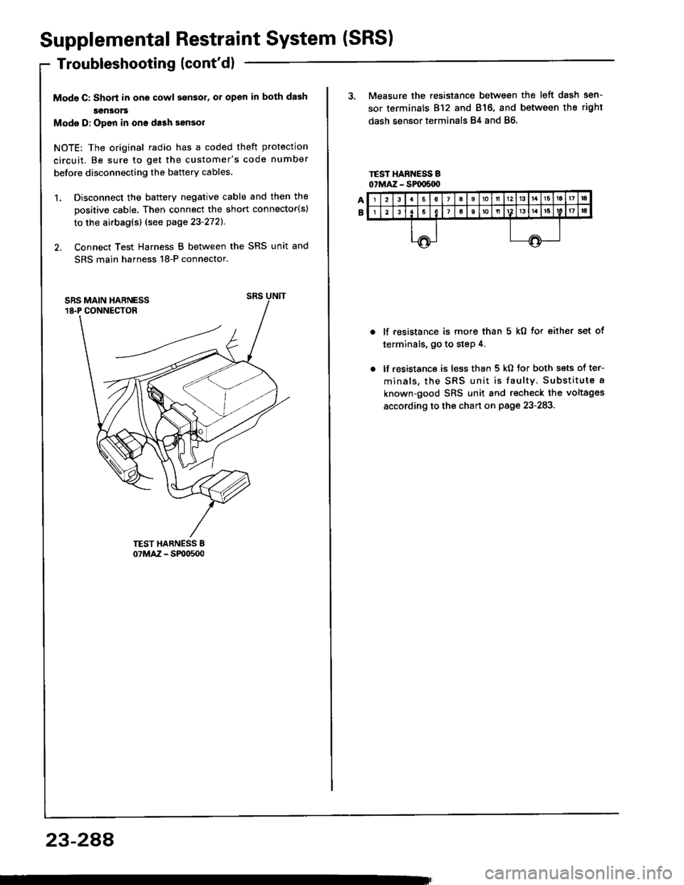
1. Disconnect the battery negative cable and then the
positive cable. Then connect the short connector(s)
to the airbag(s) (see page 23'2721.
2. Connect Test Harness B between the SRS unit and
SRS main harness 18-P connector.
23-2AA
3. Measure the resistance between the left dash sen-
sor terminals 812 and 816, and between the right
dash sensor terminals 84 and 86.
lf resistance is more than 5 kO for eiiher set of
terminals, go to step 4.
lf resistance is less than 5 kO tor both sets of ter-
minals, the SRS unit is faulty. Substitute a
known-good SRS unit and recheck the voltages
according to the chart on page 23-283.
Page 1394 of 1413
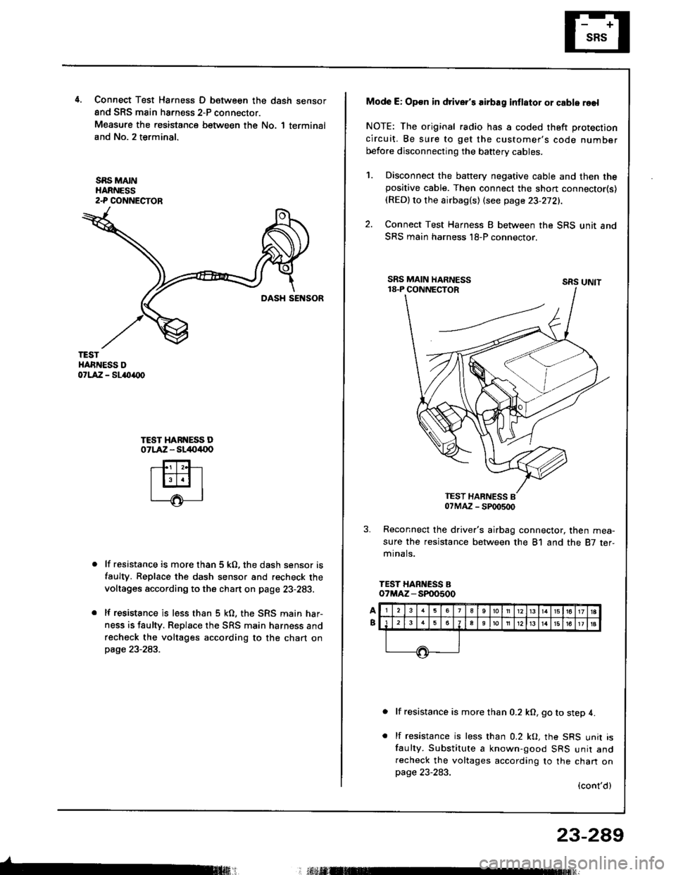
4.Connect T6st Harness D between the dash sensor
and SRS main harness 2-P connector.
Measure the resistance between the No. 1 terminal
and No. 2 terminal.
SBS MAINHARNESS2-P COI{NECTOR
TESTHARNESS DorlA:a - sl{tarx)
TEST HARI{ESS DOTLAZ - sl/to4{lo
lf resistance is more than 5 kO, the dash sensor is
faulty. Replace the dash sensor and recheck the
voltages according to the chart on page 23-283.
lf resistance is less than 5 kO, the SRS main har-
ness is faulty. Replace rhe SRS main harness and
recheck the voltages according to the chart onpage 23-283.
Mode E: Op€n in driver's airbag inflator or cable reel
NOTE: The original radio has a coded theft protection
circuit. Be sure to get the customer's code number
before disconnecting the baftery cables.
Disconnect the battery negative cable and then thepositive cable. Then connect the short connector(s)(RED)to the airbag(s) (see page 23-272).
Connect Test Harness I between the SRS unit and
SRS main harness l8-P connector.
sRs uNtt
Reconnect the driver's airbag connector, then mea-
sure the resistance between the 81 and the 87 ter,mr na ls.
TEST HARNESS Bo?MAZ - SP00500
lf resistance is more than 0.2 kO, go to step 4.
lf resistance is less than 0.2 kO, the SRS unit isfaulty. Substitute a known-good SRS unir andrecheck the voltages according to the chan onpage 23-283.
(cont'd)
23-289
; r.il M
1.
2.
Page 1395 of 1413
Supplemental Restraint System (SRS)
Troubleshooting {cont'd}
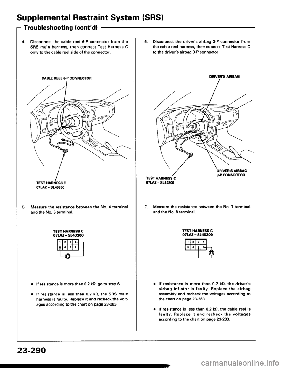
4, Disconnect the cable reel 6-P connector from the
SRS main harness, then connect Test Harness C
onlv to the cable reel side ot the connector.
CAB1I REEL &P CONNECTOB
TEST HARNESS C07LAZ - SLIO300
Measure the resistance between the No. 4 terminal
and the No, 5 terminal.
TEST HARI{ESS COTLAiZ - Sl/t{r3q)
lf resistance.is more than 0.2 ko, go to step 6.
It resistance is less than 0.2 k0, the SRS main
harness is faulry. Replace it and recheck the volt-
ages according to the chart on page 23-283.
23-290
6. Disconnect the driver's airbag 3-P connsctor from
the cabls reol harness, then connoct Test Harn6ss C
to the driver's airbag 3-P conn6ctor.
DRIVER'S AIRBAG
7.Measure the resistance between the No. 7 terminsl
and the No. 8 terminal.
TEST HARI{ESS COTLAZ - AL/|{,3OO
lf resistance is more than 0.2 kO, ths drivsr's
airbag inflator is faulty. Replace the airbsg
ass€mbly and recheck the voltages according to
the chart on page 23-283,
lf resistance is less than 0.2 kO. the cable reel is
faulty. Replace it and recheck the voltag€s
according to the chart on page 23-283.
Page 1396 of 1413
Modc F: Opon in tront pa3s6ngs/s rirbag inflstor
NOTE: The original radio has a coded theft protection
circuit. Be sure to get the customer's code number
before disconnecting the battery cables.
1, Disconnect the battery negative cable and then thepositive cable. Then connect the short connoctor{sl
{RED} to the airbag(s) (see page 23-272).
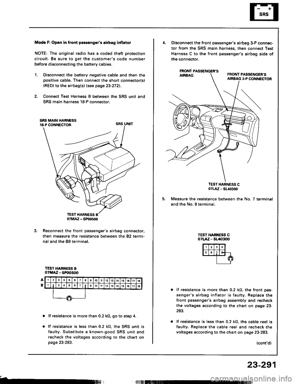
2. Connect Test Harness B between the SRS unit and
SRS main harness 18-P connector.
SRS UNIT
Reconnect the front passenger's airbag connector,
then measure the resistance between the 82 termi-
nal and the B8 terminal.
TEST HARNESS BoTMAZ - SP005(x)
lf resistance is more than 0.2 k0, go to step 4.
lf resistance is less than 0.2 kO, the SRS unit is
faulty. Substitute a known-good SRS unit and
recheck the voltages according to the chart onpage 23-283.
b
07MAZ - SP|D500
Disconnect the front passenger's airbag 3-P connec-
tor from the SRS main harness, then connect Test
Harness C to the front passenger's airbag sids of
the connector,
FAONT
TEST HARNESS C07LA,Z - SL/O300
Measure the resistance between the No. 7 terminal
and the No. 8 terminal.
TEST HAB ESS C071-Aiz - sll|{,300
lf resistance is more than 0.2 kO, the front pas-
senger's airbag inflator is faulty. Replace the
front passenger's airbag assembly and r€check
the voltages according to the chart on page 23-
243.
lf resistance is less than 0.2 kO, the cable reel is
faultv. Replace the cable reel and r€check the
voltages according to the chart on page 23-283.
(cont'd)
23-291