connector or terminal HONDA INTEGRA 1994 4.G Owners Manual
[x] Cancel search | Manufacturer: HONDA, Model Year: 1994, Model line: INTEGRA, Model: HONDA INTEGRA 1994 4.GPages: 1413, PDF Size: 37.94 MB
Page 1241 of 1413
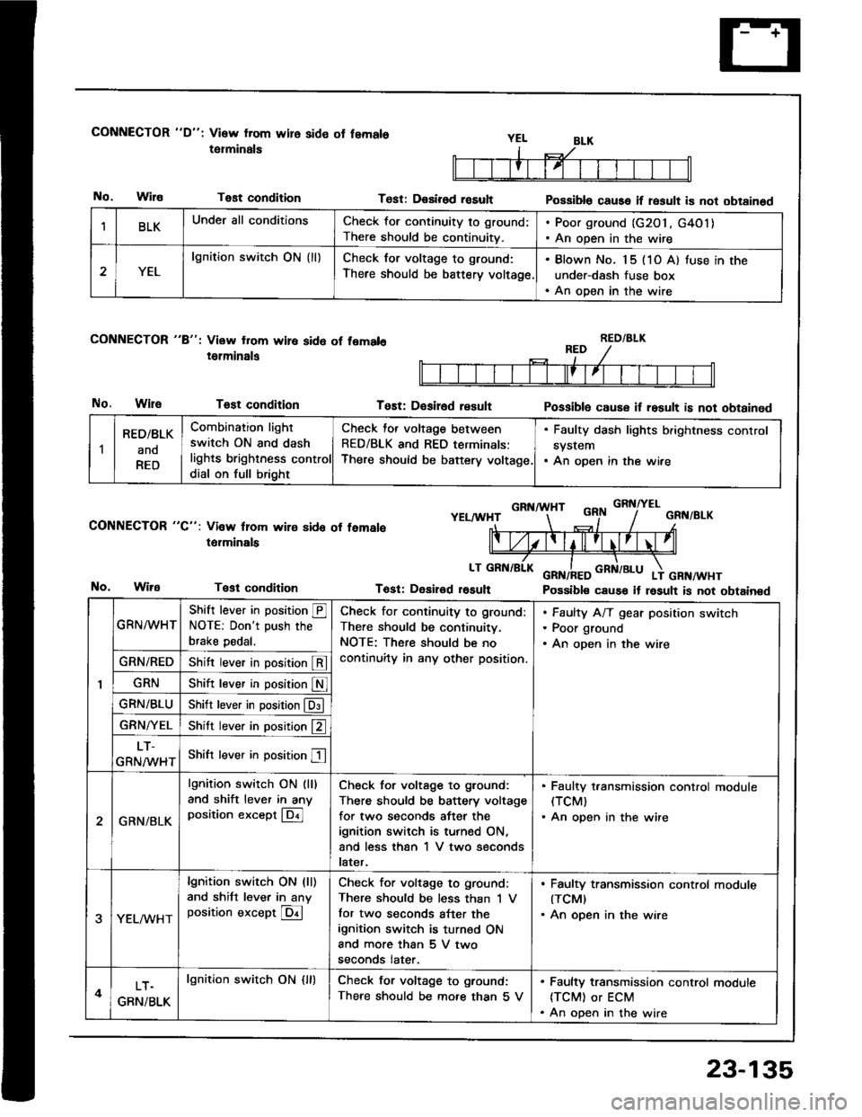
CONNECTOR "D": Visw from wire side ot femals
tetminals
No.WilaTest condition
CONNECTOR "8": View from wire sid6 of fem.l6
i6lminals
No.WileTost condition
CONNECTOR "C": Vi3w lrom wire sido of temale
t6rminals
Test condition
Test: D€sirod rasultPossible cause if result is not obtainod
Tost: D€sir6d resultPossiblo cause if result is not obtained
GRNA HTGRNITELYELAA'HTGRN/BLK
Tost: Desirod r6sult Possible cause it result is not obtainedNo.
BLKUnder all conditionsCheck for continuity to ground:
There should be continuitv.
. Poor ground (G2O1, G4O1). An open in the wire
2YEL
lgnition switch ON { ll}Check for voltage to ground:
There should be battery voltage.
. Blown No. 15 (1O A) tuse in the
under-dash fuse box. An open in the wire
RED/BLK
1
RED/BLK
ano
RED
Combination light
switch ON and dash
lights brighlness control
dial on full bright
Check for voltage between
RED/BLK and RED terminals:
There should be baftery voltage.
. Faulty dash lights b.ightness control
system. An open in the wire
GRN^^/HT
Shift lever in position @NOTE: Don't push the
brake pedal.
Check for continuity to ground:
There should be continuitv.
NOTE: There should be no
continuity in any other position.
Faulty A/T gear position switch
Poor ground
An open in the wire
GRN/REDShift lever in position @
GRNShift lever in position S
GRN/BLUShitr lever in position @
GRN/YELShitt lever in position f2 ]
LT-
GRNMHTShift lever in position E
2GRN/BLK
lgnition switch ON (ll)
and shift lever in anyposition except @
Check for voltage to ground:
There should be battery voltage
for two seconds after the
ignition switch is turned ON,
and less than 1 V two seconds
later.
. Faulty t,ansmission control module(TCM)
. An open in the wire
3YEL/vVHT
lgnition switch ON (ll)
and shitt lever in anyposition except @
Check for voltage to ground:
There should be less than 'l V
tor two seconds after the
ignition switch is turned ON
and more than 5 V two
seconds later.
. Faulty transmission control modute(TCMI
. An open in the wire
4LT.
GRN/BLK
lgnition swirch ON {ll}Check for voltage to ground:
There should be mofe than 5 V
. Faulty transmission control module
ITCM) or ECM. An open in the wire
23-135
Page 1243 of 1413
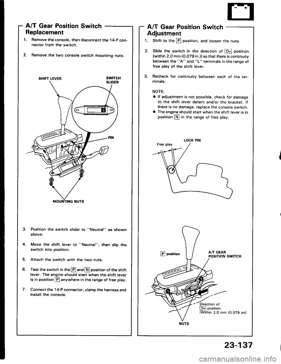
Replacement
Remove the console, then disconnect the 14-P con-nectof from the switch.
Remove the two console switch mounting nuts.
swtTcH
A/T Gear Position SwitchA/T Gear Position Switch
Adjustment
1. Shift to the ill position, and loosen the nuts.
2. Slide the switch in the direcrion of E position
[within 2.O mm (O.079 in.)l so that there is continuity
between the "A" and "L" terminals in the ranqe of
free plsy oJ the shiJt lever.
3. Recheck for continuity between each ot the ter-
minals.
NOTE:
a lf adiustment is not possible. check for damage
to the shiJt lever detent and/or the bracket. lfthere is no damage, replace the console switch.a The engine should start when the shift lever is inposition LN] in the range of free play.
@ porition
Position the switch slider to "Neutral" as shown
above.
4. Move the shift lever to
switch into position.then slip the
Attach the switch with the two nuts.
Test the switch in the @ and E] position ot the shift
lever. The engine should sta.t when the shift leveris in position p anywhere in the range of free play.
Connect the 14-P connector, clamp the harness andinstall the console.
SHIFT LEVER
LOCK PIN
NUTS
23-137
Page 1247 of 1413
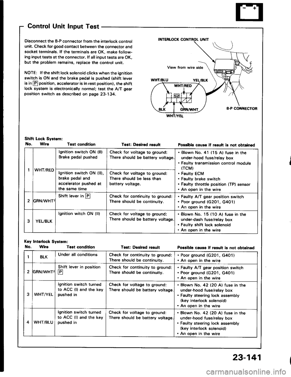
Control Unit Input Test
Oisconnect the 8-P connector from the interlock control
unit. Check for good contact between the connector and
socket terminals. lf the terminals 8re OK, make Iollow-
ing input tests at the connector. lf all input tests are OK,
but the problem remains, replace the cont.ol unit,
NOTE: lf the shilt lock solenoid clicks when the ignition
switch is ON and the brake pedal is pushed (shift tever
is in lfl position, accelerator is in rest position), the shiftlock system is electronically normal; test the A/T gear
positaon switch as described on page 23- 134.
Shift Lock Sy.tem:
No, Wlr6 Tost condition
Koy Intodock Systam:
No. WireT6st condition
Tost: Dosired resultPossiblo cause if rssuh is not obtainod
T6st: Desiled reaultPossible caure if rosult is not obtainsd
'I
lgnition switch ON (ll)
Brake pedal pushedCheck for voltage to ground:
There should be bsttery voltage
Blown No. 41 (15 A) fuse in the
under-hood fuse/relay box
Faulty transmission control module(TCM}
Faulty ECM
Faultv brake switch
Faulty throftle position lTP) sensor
An oDen in the wire
wn t/hEulgnition switch ON
brske pedal and
accelerator pushed
the same time
I [),
at
Check for voltage to ground:
There should be less than
battery voltage.
GRN^/vHT'
Shift lever in @Check lol continuity to ground:
There should be continuity.
Faulty A/T gear position switch
Poor ground {G201, G401}
An oDen in the wire
YEL/BLK
lgnition witch ON (lllCheck for voltage to ground:
There should be battery voltage
Blown No. 15 (10 A) luse in the
under-dash fuse/relay box
Faulty shift lock solenoid
An oDen in the wire
BLKUnder all conditionsCheck for continuity to ground:
There should be continuitv.
. Poor ground (G2O1, G4O1). An ooen in the wire
2
Shift lever in position
E
Check for continuity to ground;
Ther€ should be continuity.
Faulty A/T gear position swirch
Poor ground (c2O1 , G4O1)
An oDen in the wire
3WHTAYEL
lgnition switch tu.ned
to ACC (ll 8nd the keypushed in
Check for voltage to ground:
There should be battery voltage
Bfown No. 42 l2O Al fuse in the
under-hood tuse/relay box
Faulty steering lock assembly(kev interlock solonoid)
An oDen in the wire
4WHT/BLU
lgnition switch turned
to ACC (ll and the keypushed in
Check tor voltage to ground:
There should be batery voltage,
Bfown No. 42 l2O Al fuse in the
under-hood fuse/relav box
Faulty steering lock assembly(key interlock solenoid)
An oDen in the wire
23-141
Page 1248 of 1413
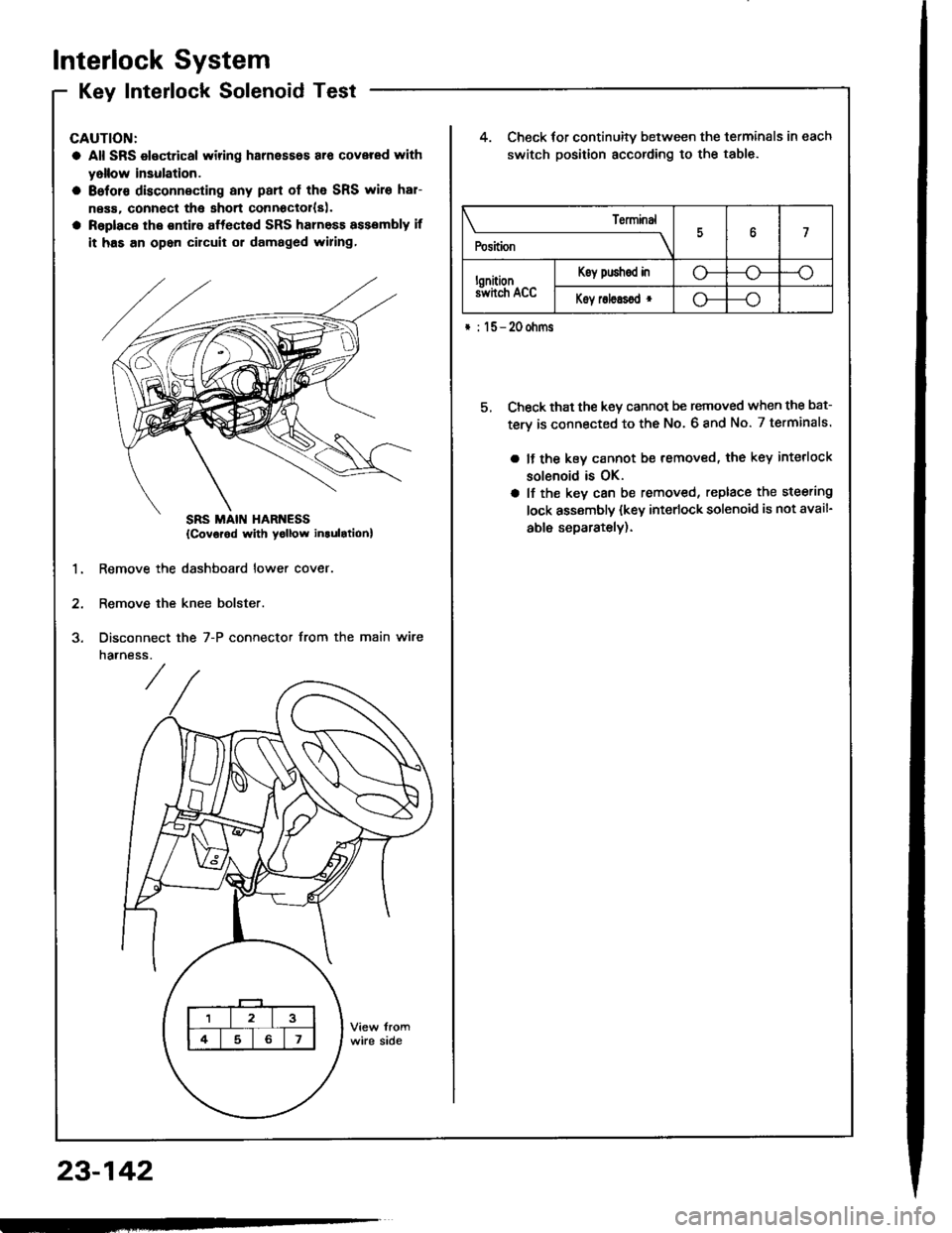
Interlock System
Kev Interlock SolenoidTestKey IntenocK Dorenoro I esr -
CAUTION:
a All SRS electrical wiring harnesses ar€ covered rYith
yollow insulation.
a 8eforc disconnecting any pan of the SRS wire har-
ness. connecl tha short connoclol{s|.
a Raplace the ontire affected SRS harness assembly if
it has an opon circuit or damaged wiring,
4. Check for continuitv between the terminals in each
switch position according to the table.
5, Check that the key cannot be removed when the bat-
tery is connected to the No. 6 8nd No. 7 terminals.
a It the kev cannot be removed, the key interlock
solenoid is OK.
a lf the key can be removed, replace the steering
lock assembly (key interlock solenoid is not avail-
able separately).
1.Remove the dashboard lower cover
Remove the knee bolster.
Disconnect
narness.
the 7-P connector from the main wire
\______________rry
Position7
lonitionS hch Acc
Koy push€d ino---o
Koy roleEsod r--o
* : l5-20ohms
{Covorod with yollow inlulrtionl
23-142
Page 1252 of 1413
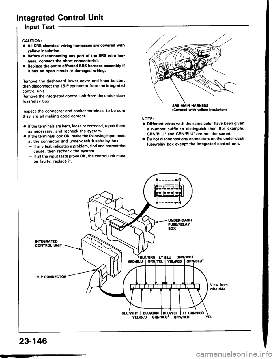
Integrated Control Unit
Input Test
CAUTION:
a All SRS elocttical widng hatness€s ato covored with
yollow insulation.
a Botolo disconnocring any pan ot the SRS wile hal'
ness, conn€ct tho shon connoctor(3l.
a Replaca tho ontlrg affsctod SRS hE noaa assombly if
it has an opon circuit or damag6d wifng.
Remove the dashboSrd lower cover and knee bolstar.
then disconnect the 1 5-P connector Jrom the integratsd
control unit.
Remove the integrated control unit from the under-dash
Juse/relav box.
Inspect the connector and socket tetminals to be sure
they are all making good cont8ct.
a lf the terminals are bent, loose ot corrod€d, repair them
as necessary, and recheck the system
a lf the terminals look OK, make the tollowing input tssts
at the connector and under-dash tuse/relsy box.
- lf any test indicates a problem, find and correct the
cause, then recheck the system.- It all the input tests prove OK, the control unit must
be faulty; replace it.
15.P CONNECTOR
NOTE:
a Diftorent wires with the sam€ color have been given
a number suffix to distinguish th€n {for 6xample,
GRN/BLUI and GRN/BLU'�are not the same).
a Do not disconnect any connectors on tho under-dash
fu8e/relay box except the integratsd contlol unit.
BLU/WHT I BLU/GR]{ I BLU/YEL I LT GB /BED
23-146
SRS MAII{ HARI{ESS
H_____-t{
.BLK/GBI{ LT
YEL/BLU GRN/BLUI GRI{/RED
Page 1256 of 1413
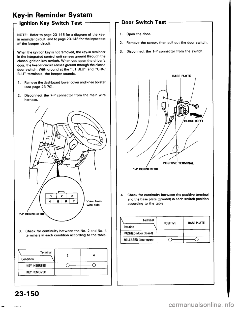
Key-in Reminder System
lgnition Key Switch Test
NOTE: Refer to page 23-145fot a diagram of the key-
in leminder circuit, and to page 23-148 Jor the input test
ol the beeper circuit.
When the ignition key is not removed, the key-in reminder
in the integrated control unit senses ground through the
closed ignition key switch. When you open the driver's
door, the beeper circuit senses ground through the closed
door switch, With ground at the "LT BLU" and "GRN/
BLU" terminals, the beeper sounds.
1 . Remove the dashboard lower cover and knee bolster
(see page 23-70).
2. Disconnect the 7-P connector from the main wire
harness.
Check for continuity between the No. 2 and No. 4
terminals in each condition acco.ding to the table.
l.
Door Switch Test
Open the door.
Remove the screw, then pull out the door switch.
Disconnect the 1-P connector from the switch.
4. Check lor continuity between the positive terminal
and the base plate (ground) in each switch position
according to the table.
BASE PLATE
Position
TerminalPOSITIVEBASE PLATE
PUSHED {door closedl
RELEASED ldoor o!en)oo
Terminal
Condition
4
KEY INSERTED--o
KEY REMOVED
23-150
Page 1257 of 1413
Engine Oil Pressure
Indicator System
Description
NOTE: Reter to page 23-144 tor the circuit diagram otthe engine oil pressure indicator flasher, snd to page
23-148 lor the input test of the flasher circuit.
The low engine oil pressure indicator tight works in twoways. lt will flash continuously following a momentaryloss of oil pressure, or it will go on and stay on with acomplete loss of oil pressure.
When the engine first starts, before oil Dressure risesabove 29.4 kP8 10.3 kgf/cmr, 4.3 psi), current flowsthrough the low engine oil pressure indicator light andthe oil pressure switch to ground. This tests the circuit.
Wilh the engine running, voltage is applied ro the ftash-er circuit of the integrated control unit. With normal oilpressure, the oil pressure switch is open and the low en-gine oil pressure indicator light does not operate. lf theoil pressure switch closes momentarily (more than O.5secondsl, but then opens again, terminal "yEL/RED,'will
sense ground through the switch. The integrated con-trol unit willthen provide and remove ground for th€ lowengine oil pressure indicator light through terminal"YEL/RED". The light will flash on and olf until the igni-tion switch is turned to "OFF".
lf engine oil pressure falls below 29.4 kPa (O.3 kgJ/cmr,4.3 psi) and does not increase, the oil pressure switchwillstsy closed. The low engine oilpressure indicator lightwill go on and stav on.
NOTE; Refer to page 23-122lot the engine oil pressure
switch test.
Lights-on Reminder
System
Description
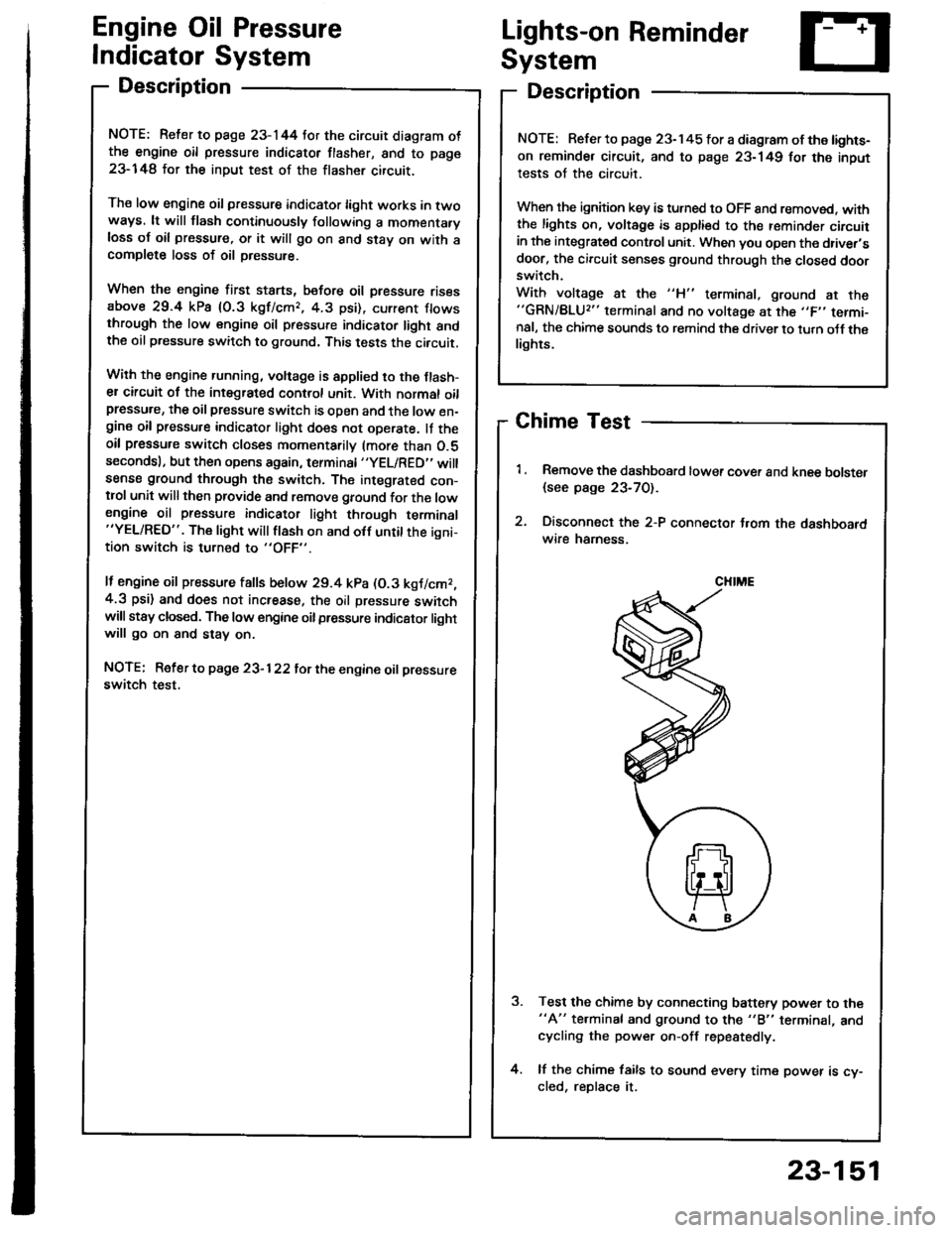
Chime Test
Remove the dashboard lower cover and knee bolster
{see page 23-70).
Disconnect the 2-P connector t.om the dashboardwire hamess.
Test the chime by connecting battery power to the"A" te.minal and ground to the "B" terminal, andcycling the power on-off repestedly.
lf the chime fails to sound every time power is cy-cled, reDlace it.
NOTE: Refer to page 23-145 tor a diagram of the lights-
on reminder circuit, and to page 23-149 for the input
tests of the circuit.
When the ignition key is turned to OFF 8nd removed. withthe lights on, voltage is apptied to the reminder circuitin the integrat€d control unit. When you open the driver,sdoor, the circuit senses ground through the closed doorswitch.
With voltage at the "H" terminal, ground at the"GRN/BLU2" terminal and no voltage at the ,,F,' termi-nal, the chime sounds to remind the driver to turn oJf thelights.
CHIME
23-151
Page 1262 of 1413

Lighting System
Daytime Running Lights Control Unit Input Test (Canada)
CAUTION:
a All SRS eloc{dcal wi ng harn€sses are covelod with
yollow insulation.
a Boforo dbconnocting any psrt of the SRS wir€ h8r-
noss, connoct tho shon connector(s).
a Roplace the entire affected SRS harness assombly it
it has an opon Gilcuit or damagod wifng.
1 . Remove the dashboard lower cover and knee bolster.
2. Disconnect the connectors from the daytime running
lights control unit.
3. Insoect the connectof and socket terminals to be
sure they are all making good contact.
a ll the terminals are bent, loose or coroded, repair
them as necessary. and recheck the system,
a lf the terminals look OK, make the following in-
put tests at the connector,- lf any test indicates a problem, find and cor-
.ect the cause, then recheck the system.- ll allthe input tests prove OK, the control unit
must be taulty; replace if
4-P CONI{ECTOR
WHT/RED
YEL/ALK
8-P CONNECTOR
GRN/RED
WHTA'EL
23-156
View from wire sideVi6w from ware side
RED/GRI{
Page 1264 of 1413
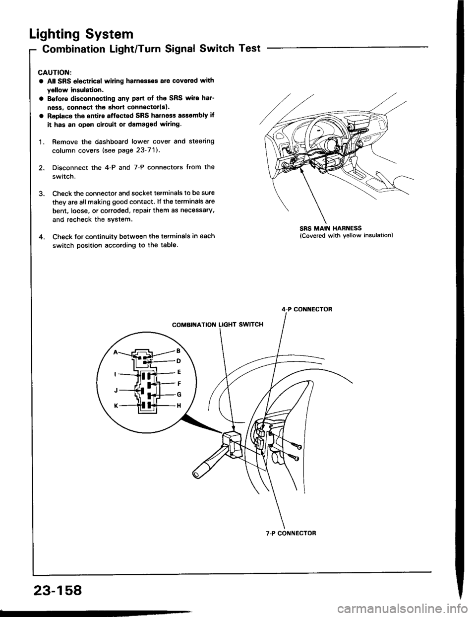
Lighting System
Combination Light/Turn Signal Switch Test
CAUTION:
a Atl SRS Oloctricsl wiring harnesses ar6 covered with
yellow insulation.
a Bslor€ disconnecting any pan ot the SRS wire har-
ness, connact the short connsctollsl.
a Replace the sntire aftectad SRS harne$ assembly if
it has an opon circuit or damagod wiring.
1. Remove the dashboard lower cover and steering
column covers (see page 23-71).
2. Disconnect the 4-P and 7-P connectors from the
switch.
3. Check the connector and socket tetminals to be sure
they are all making good contact. lf the terminals are
bent, loose, or cotroded, repair them as necessary,
and recheck the system.
4. Check tor continuitv between the terminals in each
switch position according to the table.
SRS MAIN HAR ESS
B
D
G
H
4-P CONI{ECTOR
7.P CONNECTOR
23-158
Page 1266 of 1413
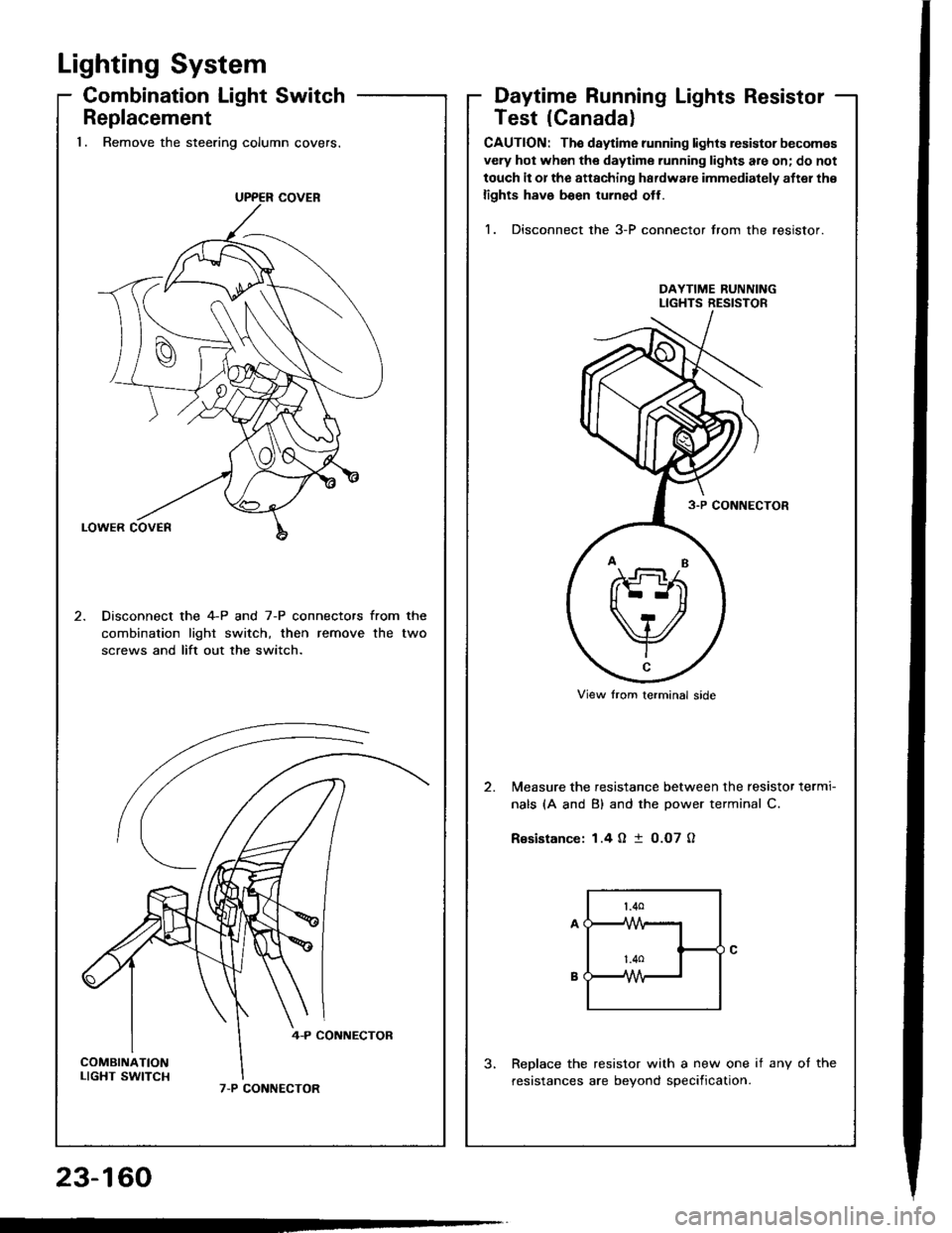
Lighting System
Combination Light Switch
Replacement'1. Remove the steering column covers.
Disconnect the 4-P and 7-P connectors from the
combination lighr switch, then remove the two
screws and lift out the switch.
Daytime Running Lights Resistor
UPP€R COVER
Test lCanada)
CAUTION: The daytime running lights resistor becomas
vely hot when the daytime running lights are on; do not
touch it or the attaching hardware immediately aftel th€
lights h8ve b€en turned otf.
1. Disconnect the 3-P connector from the resistor.
DAYTIME RUNNINGLIGHTS RESISTOR
Measure the resistance between the resistor termi-
nals (A and B) and the Dower terminal C.
R€sistance: 1.4 O I O.O7 O
Replace the resistor with a new one if any ot the
resistances are bevond soecification.
?nd
V-c
View trom lerminal side
23-160