connector or terminal HONDA INTEGRA 1994 4.G Workshop Manual
[x] Cancel search | Manufacturer: HONDA, Model Year: 1994, Model line: INTEGRA, Model: HONDA INTEGRA 1994 4.GPages: 1413, PDF Size: 37.94 MB
Page 1298 of 1413
![HONDA INTEGRA 1994 4.G Workshop Manual Terminals
Connects to
\
*i,.,-terlll
FO] ANTENNA LEADA
TI!NM[IAL
A9---------+A16
Stereo Sound System
Stereo Radio/Cassette PlayerFront Speaker/Tweeter
Replacement
Front Spoakor:
1. Carefully pry out t HONDA INTEGRA 1994 4.G Workshop Manual Terminals
Connects to
\
*i,.,-terlll
FO] ANTENNA LEADA
TI!NM[IAL
A9---------+A16
Stereo Sound System
Stereo Radio/Cassette PlayerFront Speaker/Tweeter
Replacement
Front Spoakor:
1. Carefully pry out t](/img/13/6067/w960_6067-1297.png)
Terminals
Connects to
\
*i,.,-terlll
FO] ANTENNA LEADA
TI!NM[IAL
A9---------+A16
Stereo Sound System
Stereo Radio/Cassette PlayerFront Speaker/Tweeter
Replacement
Front Spoakor:
1. Carefully pry out the speaker cover.
2. Remove the three screws, then disconnect the 2-P
connector Jrom the speaker, and remove the
speaker.
2.P CONNECTOR
Twootor:
1. Remove the door panel and disconnect the tweeter
2-P connector.
2. Remove the two screws, then remove the tweeter
ano covet.
r^l
It
\7
rSPEAKERCOVER
A1RED/GRNFront passenger's door speaker O
A2BLU/GRNDriver's door speaker @
A3RED/BLKLights-on signal
A4WHT/8LUConstant power {Tuning memory)
A5YEL/REDACC (Main stereo powe. supplyl
A6YEL/GRNRadio switched power (To antenna)
A7BLU/YELLeft rear speaker O
A8RED/YELRight rear speaker @
A9BRN/BLKFront passenger's door speaker O
A10GRY/BLKDriver's door speaker O
A lnot used)
412(not used)
A13(not usedl
A14BLKGround (G551)
Al5GRY/WHTLeft rear speaker O
A16BRNAA/HTRight rear speaker e
23-192
IFrIFit
Page 1300 of 1413
Stereo
Power
Sound
Antenna
System
Motor Test
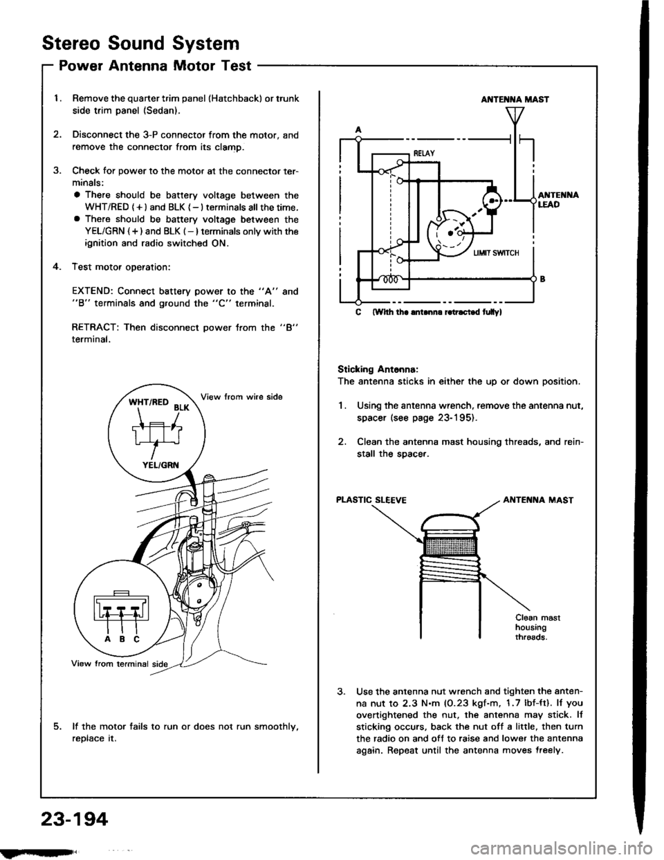
Remove the quarter trim panel (Hatchback) or trunk
side trim panel (Sedan).
Disconnect the 3-P connector from the motor, and
remove the connector from its clamD.
Check for power to the motor at the connector ter-
minals:
a There should be battery voltage between the
WHT/RED (+l and BLK {-} terminals all thetime.a There should be battery voltage between the
YEL/GRN {+) and BLK (-} terminals onlv with the
ignition and radio switched ON.
Test motor oDeration:
3.
4.
EXTEND: Connect battery power to the "A"
"B" terminals and ground the "C" terminal.
8no
"4"RETRACT: Then disconnect power trom the
terminal,
lf the motor fails to run or does not run smoothlv,
reDtace tr.
*ft'^to
?r*
TIFIT*r'
YEL/GRN
AI{TE T{A MAST
AI{TEI{I{ALEAD
C ftYhh lha lnLnn. r.tr.ci.d t|Ilyl
Sticking Ant6nna:
The antenna sticks in either the up or down position.
1.Using the antenna wrench, remove the antenna nut,
spacer (see page 23-195).
Clean the antenna mast housing threads, and rein-
stall the soacer.
PLASTIC SLEEVEAIITENNA MAST
Cloan masthousingthroads.
Use the antenna nut wrench and tighten the anten-
na nut to 2.3 N.m (0.23 kgf-m, 1.7 lbf-tt). lJ you
overtightened the nut. the antenna may stick. lf
sticking occurs, back the nut off a little, then turn
the radio on and off to raise and lower the antenna
again. Repeat until the antenna moves treely.
23-194
fmft,
Page 1304 of 1413
Clock
Replacement
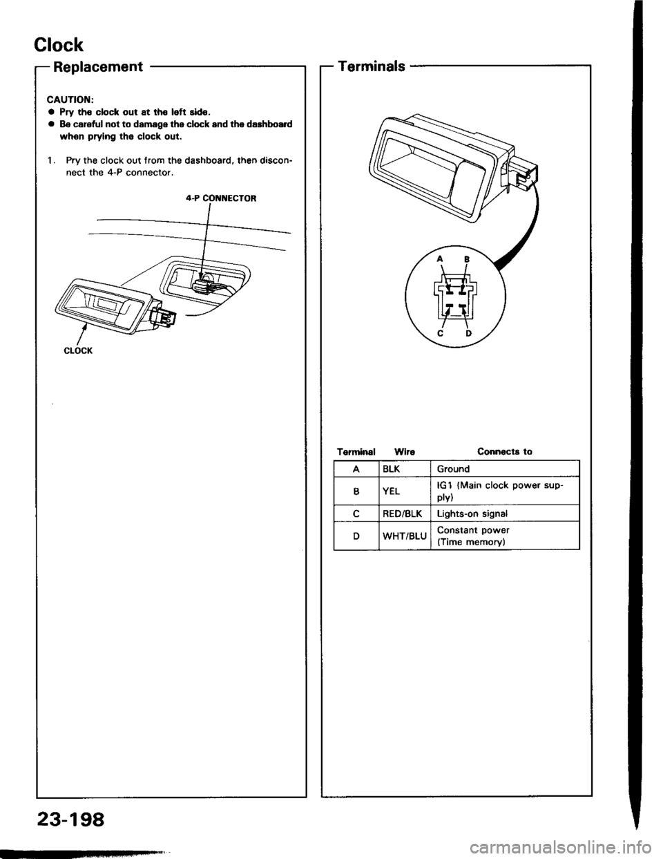
CAUTION:
a Pry th6 clock out at th€ left sido,
a Be carsful not to damage the clock and the dashboE d
whon prying the clock out.
1. Pry the clock out from the dashboard, then discon-
nect the 4-P connector.
4-P COI{NECTOR
CLOCK
23-198
Terminals
Torminal WiroConnecta to
ABLKGround
YELplv){Main clock power sup-
RED/BLKLights-on signal
DWHT/BLUConstant power
(Time memory)
Page 1307 of 1413
Switch Test
CAUTION:
a All SRS el6ctrical wiring harnossos are covarod withyellow inaulation.
a Beforo disconnecting any pan ot the SRS wire har-neaa, connoct ths short connector(s).a Roplace the entil€ afloctod SRS harne$ a$6mbly ifit has an open circuit or dsmagad wlring.
NOTE; The original radio has a coded theft protection
circuit. Be sure to get the customer's code number before- disconnecting the battery.- removing the No. 32 {7.5 A) fuse lrom the under-hoodtuse/relav box.- removing the radio.
After service, reconnect power to the radio and turn iton. When the word "CODE" is displayed, enter the cus-tomer's 5-digit code to restore radio operation.
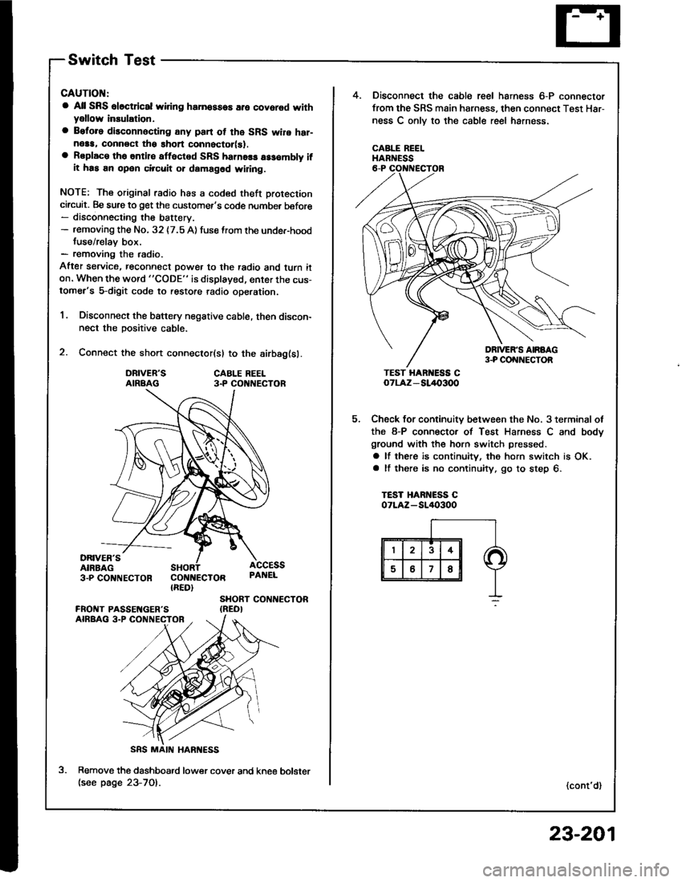
1. Disconnect the battery negative cable, then discon-nect the positive cable.
2. Connect the short connector(sl to the airbag(sl.
DRIVER'SAIRBAGCABLE REEL3.P CO NECTOR
DRIVER'SAIRBAG3-PCO'TNECTOR COI{NECTOR{RED}
ACCESSPAI{EL
SHORT CONTIECTOR{REO}
Remove the dashboatd lower cover and kne€(see page 23-701.
5.
4. Disconnect the cable reel harness 6-P connector
from the SRS main harness, then connect Test Har-
ness C onlv to the cable reel harness.
CABLE REELHARNESS
TEST HAR ESS CoTLAz - SL/l{,3OO
Check for continuity between the No, 3 terminal ot
the 8-P connector of Test Harness C and body
ground with the horn switch pressed.
a lf there is continuity, the horn switch is OK.a lf there is no continuity, go to step 6.
TEST HARNESS COTLAZ-SI/I()3OO
(cont'd)
bolster
23-201
Page 1320 of 1413
Moonroof
Function Test
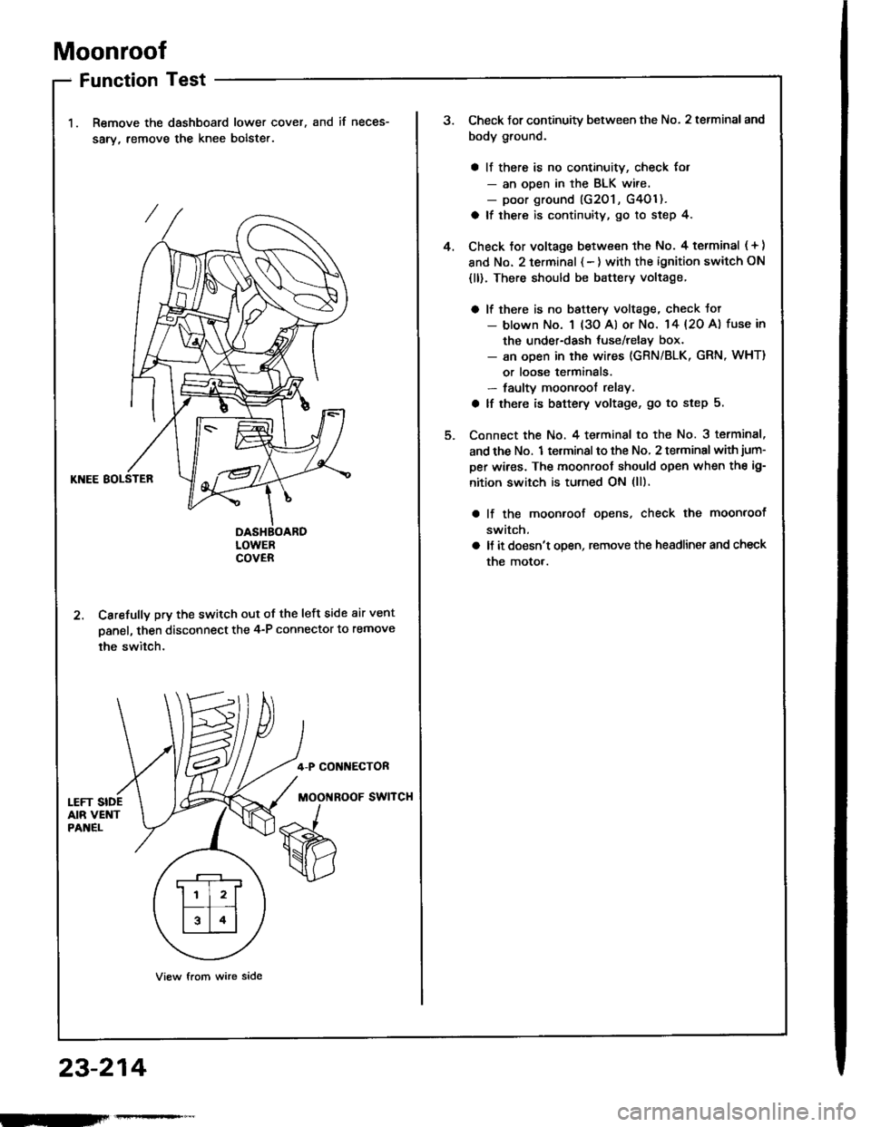
Remove the dashboard lower cover,
sarv, remove the knee bolste..
and if neces-
KNEE BOLSTER
DASHBOARDLOWERCOVER
2. Carefully pry the switch out of the left side air vent
panel, then disconnect the 4-P connector to remove
the switch.
4-P CONI{ECTOR
MOOi{ROOF SWITCH
View from wire side
.r--r
ll l2lf--T� --t
l314l
23-214
Check Jor continuity between the No. 2 terminal and
body ground.
a ll there is no continuity, check for- an ooen in the BLK wire.- poor ground (G201 , G4Ol ).
a lf there is continuity, go to step 4.
Check tor voltage between the No. 4 terminal ( + )
and No. 2 terminsl { - ) with the ignition switch ON
{ll). There should be battery voltage.
a lf there is no baftery voltage, check tot- blown No. 1 (3o Al or No. 14 {20 A) fuse in
the under-dash tuse/relay box.- an open in the wires (GRN/BLK, GRN, WHT)
or loose terminals.- faulty moonroof relay.
a lf there is battery voltage, go to step 5.
Connect the No. 4 terminal to the No. 3 terminal,
and the No. 1 terminal to the No, 2 terminal with jum-
per wires. The moonroot should open when the ig-
nition switch is turned ON (ll).
lf the moonroof ooens, check the moonroof
switch,
ll it doesn't open, remove the headlinet and check
the motor.
4.
Page 1321 of 1413
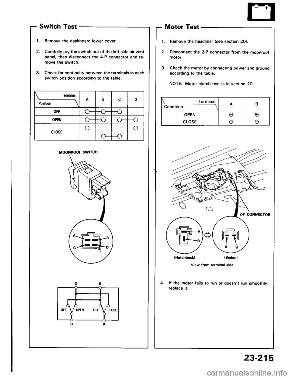
Switch Test
1, Remove the dashboard lower cover.
2. Carefully pry the switch out of the left side air vent
Danel, then disconnect the 4-P connector and re-
move the switch.
3. Check lor continuity between the terminals in each
switch position sccording to the table,
MOONROOF SWITCH
Motor Test
Remove the headliner (see section 20).
Disconnect the 2-P connector from the moonroot
moror.
Check the motor by connecting power and ground
according to the table.
NOTE: Motor clutch test is in section 20.
lHatchblckl (Scd!n)
View from terminal side
It the motor fails to run or doesn't run smoothly.
replace it.
4.
Torminal
P"ri i-
---__\AID
OFFG---o
OP€No---oG-
CLOSE
o---o
Te.minal
Condition -- ---------lAB
OPENo
CLOSE@
,l
rd\./ cLos€
Y
IOPEiIIOFF
23-215
Page 1325 of 1413
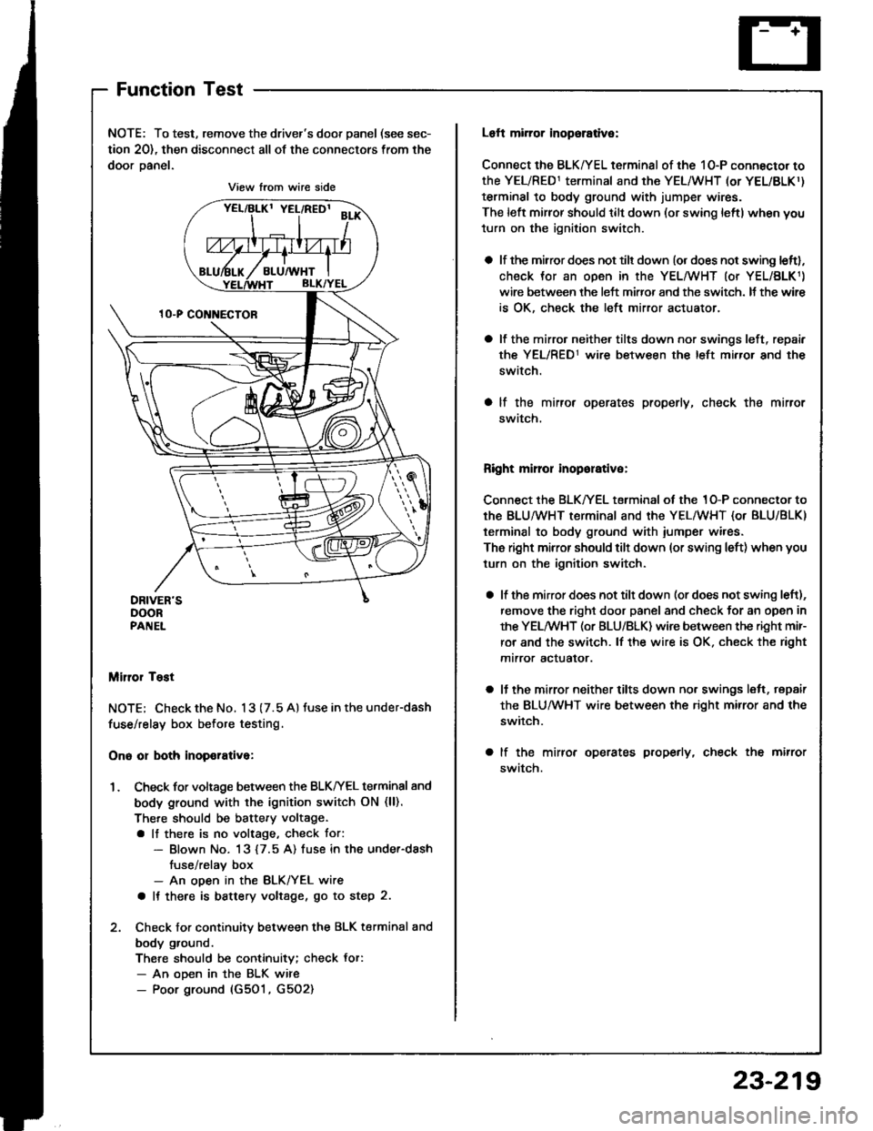
FunctionTest
NOTE: To test, remove the driver's door panel (see sec-
tion 20), then disconnect all of the connectors from the
door oanel.
Miror Tost
NOTE; Check the No. 13 (7.5 A) tuse in the under-dash
fuse/relay box before testing.
Ono or both inop€rativa:
1. Check for voltage between the BLKIrEL terminal 8nd
body ground with the ignition switch ON (ll).
There should be battery voltage.
a lf there is no voltage, check tor:- Blown No. 13 {7.5 A) fuse in the under-dash
fuse/relav box- An ooen in the BLK/YEL wire
a It there is battery voltage, go to step 2.
2. Check for continuity between the BLK terminal and
body ground.
There should be continuity; check Jor:- An ooen in the BLK wire- Poor ground (G501, G5O2)
View from wire side
Loft mirror inopsrative:
Connect the BLK/YEL terminal of the 10-P connector to
the YEL/RED1 terminal and the YEL/WHT (or YEL/BLKr)
terminal to body ground with jumper wires.
The left mirror should tilt down (or swing leftl when you
turn on the ignition switch.
a lf the mirror does not tilt down (or does not swing leftl,
check Jor an open in the YEL/WHT (or YEL/BLK1)
wire between the left miffor and the switch. It the wir€
is OK, check the left mirror actuator.
a lf the mirro. neither tilts down nor swings left, repair
the YEL/RED1 wire between the left mirror and the
switch.
a lf the mirror operates properly, check the mirror
swatch.
Right mirror inoporative:
Connect the BLK/YEL terminal of the 1O-P connector to
th€ BLU/WHT terminal and the YEL/WHT {or BLU/BLK)
terminal to body ground with iumper wires.
The right mirror should tilt down (or swing left) when you
turn on the ignition switch.
a lf the mirror does not tilt down (or does not swing left),
remove the right door panel and check for an open in
the YELMHT (or BLU/BLK) wire between the right mir-
ror and the switch. lf the wire is OK. check the right
mtrror actualor.
a ll the mirror neither tilts down nor swings lelt, repair
the BLUMHT wire between the right mirror and the
switch.
a lf the mirror operates properly, check the mirror
swatch.
23-219
Page 1326 of 1413
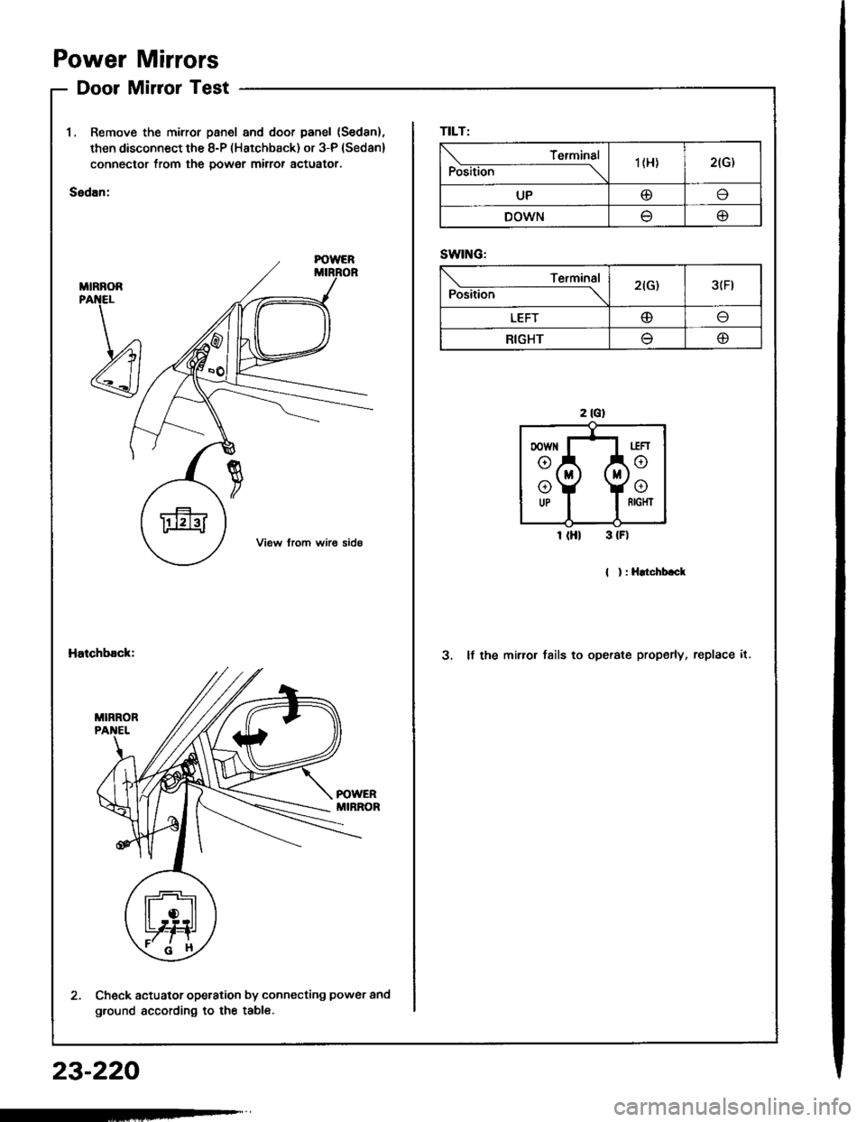
Power
Door
Mirrors
Mirror Test
1, Remove the mirror panel and door panel (Sed8n).
then disconnect the 8-P (Hatchback) or 3-P (Sedan)
connector from the power mirror actuator.
Sedan:
MIRNOR
Hatchback:3. lf the mirror fsils to operate properly, replace it.
Check actuator operation by connecting power and
ground according to the table.
TILT:
Position
Terminal'| (H)2(G)
UP@I
DOWNtJo
SWING:
Position
Terminal2(G)3(Ft
LEFTo
RIGHT(D
23-220
Page 1332 of 1413
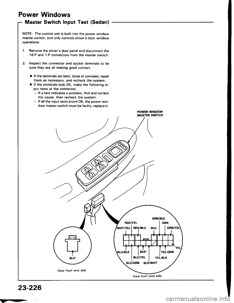
Power Windows
Master Switch Input Test (Sedan)
NOTE; The control unit is built into the Dower window
maste. switch, and onlv controls driver's door window
ooerations.
1. Remove the driver's door panel and disconnect the
16-P and 1-P connectors from the master switch.
2. Inspect the connector and socket terminals to be
sure they are all making good contact.
a lf the terminals are bent, loose or co.roded, reDair
them as necessary. and techeck the system.a It the terminals look OK, make the following in-
put tests at the connecto..- It a test indicates a problem, tind and correct
the cause, then recheck the system.- lf allthe input tests prove OK, the power win-
dow master switch must be faulty; replace it.
23-226
BEDI'EL I GRN
8LU/YEL I YEL/BLK
View from wire side
View lrom wire side
Page 1334 of 1413
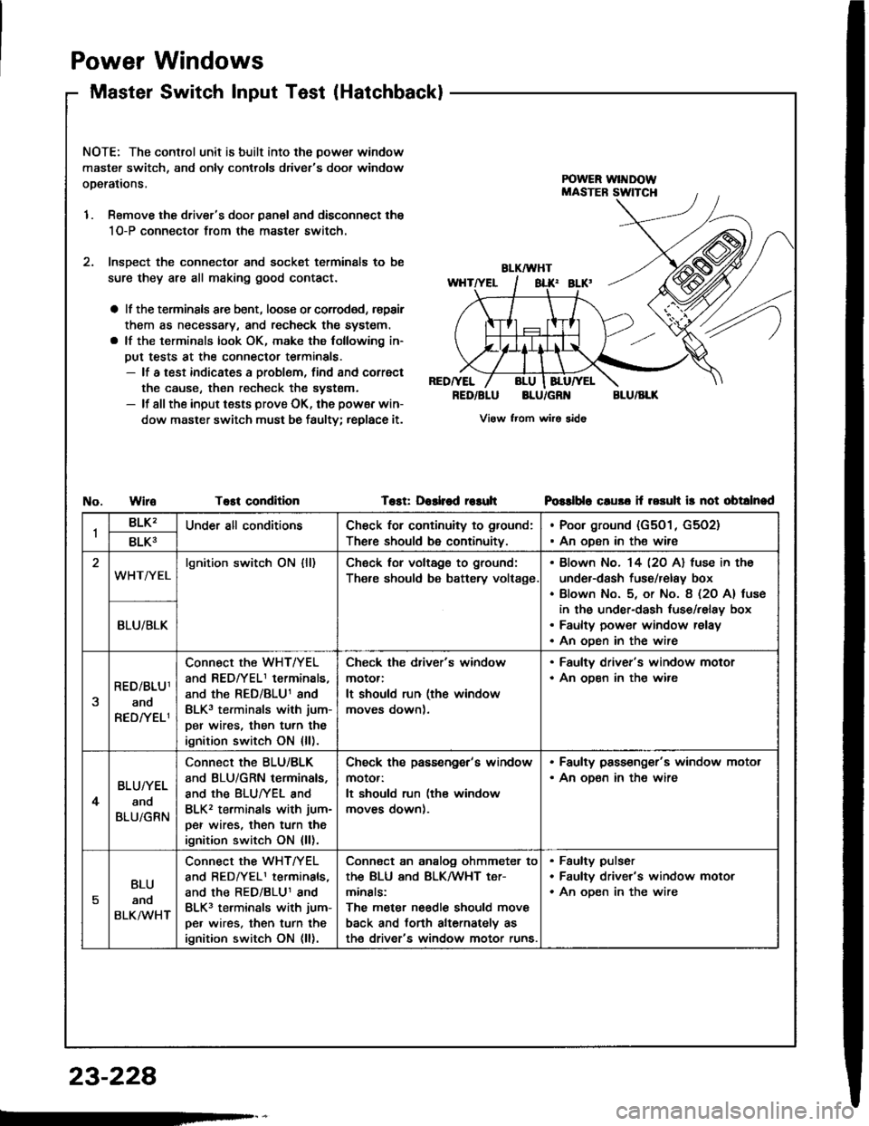
Power
Master
Windows
Switch lnput Test(Hatchback)
NOTE: The control unit is built into the power window
master switch, and onlv controls driver's door window
operations,
1. Remove the driver's door panal and disconnect the
1O-P connectol from the master switch.
2. lnsDect the connector and socket terminals to be
sure they are all making good contact.
a lf the terminsls arc bent, loose or corroded, rspair
them as necessary, and recheck the system.
a lf the terminals look OK, make the following in-
put tests at the connector terminals.- lf a test indicates a problem, find and correct
the cause, then recheck the systsm.- lf all the input tests prove OK, the powsr win-
dow master switch must be faulty; replace it.
RED/YEL
RED/BLUBLU/GR'{BLU/BLK
View from wirs sido
WiroTost conditionTost: Dashod r€suhPGslblo cluso if rosuh ir not obtalnad
1BLK'Under all conditionsCh€ck for continuity to ground:
There should be continuity.
Poor ground (G501, G5O2)
An oDen in the wire8LK3
WHT/YELlgnition switch ON {ll)Ch6ck for voltags to ground:
Th€re should be battery voltage.
Blown No. 14 l2O Al fuse in the
under-dash fuso/relay box
Blown No. 5, or No. 8 (2O A) tuse
in the under-dash luse/relay box
Faulty power window relay
An oDen in the wire
BLU/BLK
RED/BLU1
ano
RED/YELI
Connect the WHT/YEL
and REDfYELI terminals,
and the RED/BLU1 and
BLK3 terminals with jum-
per wires, then turn the
ignition switch ON {ll).
Check the driver's window
motor:
It should run (the window
moves down).
. Faulty driver's window motor. An ooen in th€ wire
4
BLU/YEL
and
BLU/GRN
Connect the BLU/BLK
and BLU/GRN terminals,
and the BLUTYEL and
BLK2 terminals with jum-
per wires, then turn the
ignition switch ON {ll).
Check ths passengor's window
motor:
It should run (the window
moves down).
. Faulty pass€nger's window motor. An oD€n in the wire
5
BLU
anq
BLKMHT
connect the WHTTYEL
and BEDrYELI terminals,
and the RED/BLU1 and
BLK3 terminals with jum-
pe. wires, then turn the
ignition switch ON (ll).
Conn€ct an analog ohmmeter to
thE BLU ANd BLKMHT t€Tr
minals:
The meter needle should move
back and torth alternately as
th€ driver's window motor runs.
Faulty pulser
Faultv driver's window motor
An oDen in the wire
23-228