connector or terminal HONDA INTEGRA 1994 4.G Workshop Manual
[x] Cancel search | Manufacturer: HONDA, Model Year: 1994, Model line: INTEGRA, Model: HONDA INTEGRA 1994 4.GPages: 1413, PDF Size: 37.94 MB
Page 1335 of 1413
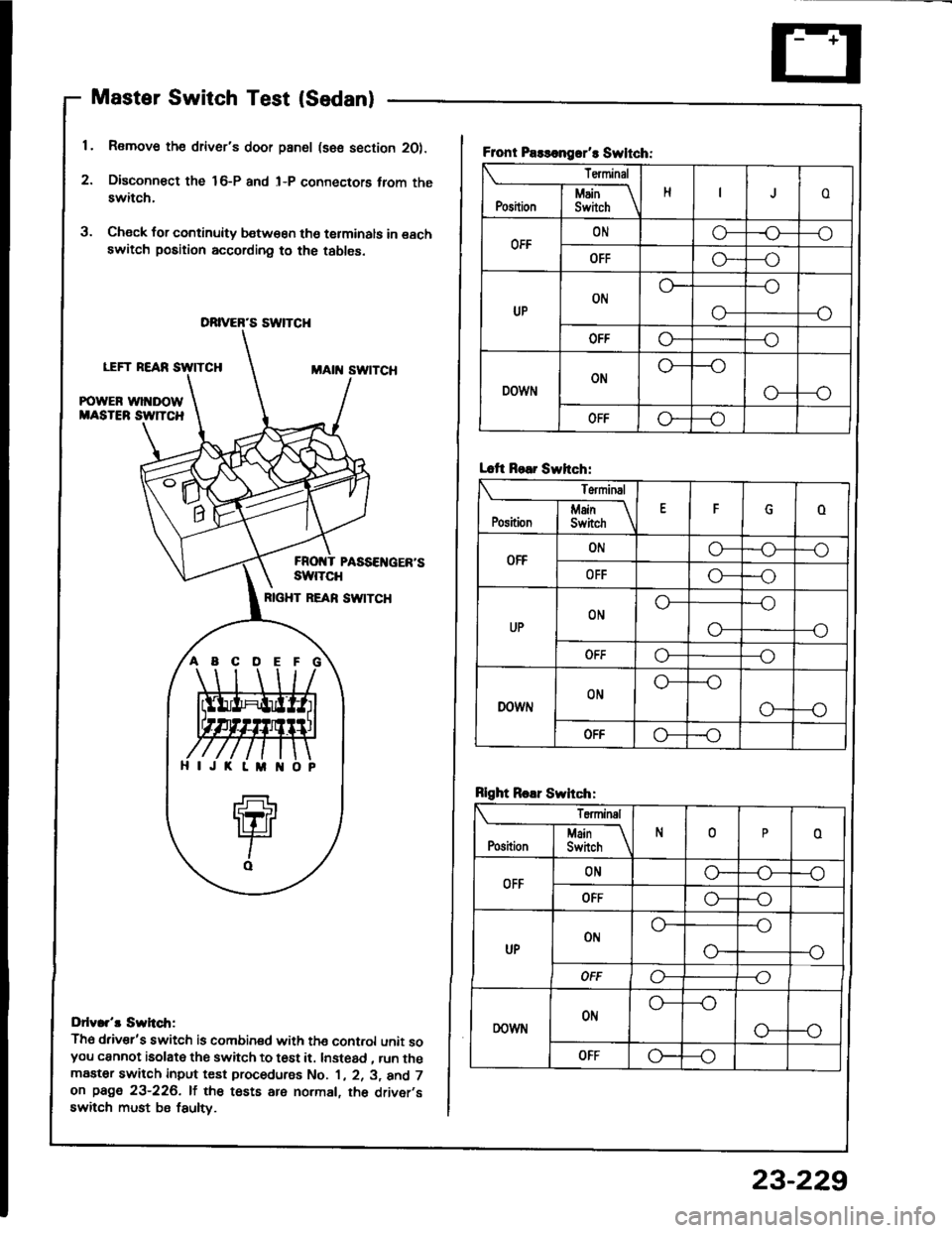
Master Switch Test (Sedan)
1. Remove the driver's door pan6l (sse section 2O).
2. Disconn€ct the 16-P and l-P connectors trom theswitch.
3. Check for continuity b€tw€€n tho terminals in eachswitch position according to the tables.
LEFT REARMAtit swtTcH
POWER wl DOWMASTEB SW]TCH
PASSEI{GER'SswtTcH
RIGHT REAN SW|TCH
Ddv.r't Swh.tr;
Th6 driv€r's switch is combined with the cont.ol unit soyou cannot isolate the switch to t6st it. Instead , run themaater switch input test procedurss No. 1 , 2. 3, and 7on page 23-226. lf the tests are normal, th6 driver,sswitch must be fsulty.
DRIVER'S SWTCH
ABCDE
Front Paslongrr't Swltch:
Terminal
HoI Main \Position I Swirch \
OFFONo-r)--o
OFFG----o
UPON
--o
O-
OFFo---o
DOWNON
o---o
OFFo--_o
Lcft Rear Swhch:
Terminal
EFoj Main IPosition I Switch \
OFFONo-o--o
OFFo---o
UPONo---o
--oo-
ut'fo---o
DOWNONo---o
G---o
OFF-o
Rlght Roar Swhch:
Teminal
N0oI Main If
Position I Switch \
OFFONG_o--o
OFFo---o
UPot'lo---o
--o
OFFo----o
DOWNONo---o
o--o
OFFG---o
23-229
Page 1336 of 1413
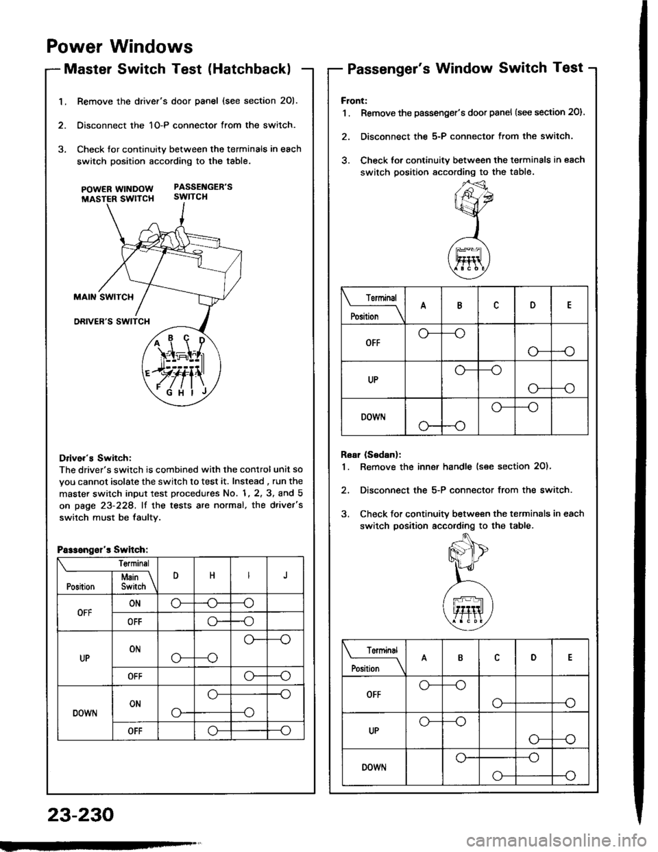
1.Remove the drivef's door panel (see section 201.
Oisconnect the 1O-P connector from the switch.
Check tor continuity between the terminals in each
switch position according to the table.
pOWERWTNDOW PASSENGEB'S
MASTER SWTTCH SWITCH
Drive.'s Switch:
The driver's switch is combined with the control unit so
you cannot isolate the switch to test it. Instead , run the
master switch input test procedures No. 1, 2, 3, and 5
on page 23-228, lf the tests are normal, the d.ivet's
switch must be faultv.
i1\i
\4r-I^l,r
)rvti\
.Fi'ilj
Passengsl'r Switch:
Te.minsl
DHJI Msin \Position I Switch \
OFFONo-(J--o
OFFo--o
UPONo---o
o--
OFFo--o
DOWNONo-
o--o
--o
OFFo--o
Power Windows
Master Switch Test (HatchbacklPassenger's Window Switch Test
23-230
Front:
1 . Remove the passenger's door panel {see section 20).
2. Disconnect the 5-P connector from the switch.
3. Check for continuity between the terminals in each
switch position sccording to the table.
Rear (Sedanl:
1. Remove the inn€r handle (see section 2O)'
2, Disconnect the 5-P connector from the switch.
3. Check for continuity between the terminals in each
switch position according to the table.
Torminal
il;_\
ARD
OFFo-
--o
UPo---o
G_--o
DOWr.lo---o
Terminal
;;__\ID
OFFG_--o
o---o
UPG_--o
o---o
DOWNo---o
o-
Page 1338 of 1413
Power Windows
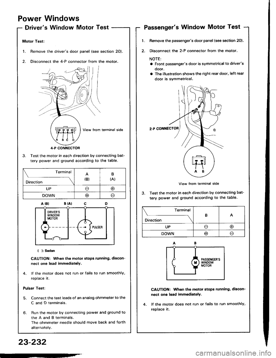
Driver's Window MotorTest
1. Remove the
2. Disconnect
Motor Test:
View from lerminal side
4.P CONNECTOR
3. Test the motor in each direction by connecting bat-
tery power and ground according to the table.
{ }: Sodan
CAUTION: When the motor stops running. discon-
nect one lead immediately.
4. lf the motor does not run or tails to run smoothly,
replace it.
Pulser Test:
5. Connect the test leads of an analog ohmmeter to the
C and D terminals.
6- Run the motor by connecting power and ground to
theAandBterminals,
The ohmmeter needle should move back and torth
alternately.
driver's door panel (see section 20).
the 4-P connector trom the motor.
. ,-,.f,/l l/
NZJI I
..Q]qql ,fiftl I
$e /tE \
Terminal
Direction(B)B
{A}
UP@
DOWNO
Passenger's Window Motor Test
l.
2.
Remove the passenger's door panel (see section 20).
Disconnect the 2-P connector from the motor.
NOTE:
a Front passenger's door is symmetricalto driver's
ooor.
a The illustration shows the right rear doot, left rear
door is svmmetrical.
2.P CONNECTOR
View from terminal side
3. Test the motor in each direction by connecting bat-
tery power and ground according to the table.
CAUTION: When the motor stops tunning. discon-
nect on€ lead imm€diately.
lf the motor does not run or Jails to run smoothly,
reDlace it.
Terminal
O*** \
BA
UPoo
DOWN@
23-232
-'
Page 1342 of 1413
Power Door Locks
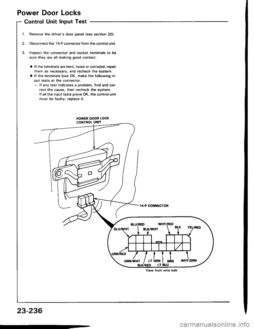
Control Unit Input Test
Remove the driver's door panel {see section 2O).
Disconnect the 1+P connector Jrom the control unit.
Inspect the connector and socket terminals to be
sure they are all making good contact.
a It the terminals are bent. loose or corroded, repair
them as necessary. and recheck the system.
a lf the terminals look OK. make the following in-
put tests at the connector.- lf any test indicates a problem, find and cor-
rect the cause, then recheck the syslem.
lf all the input tests prove OK, the control unit
must be faultv; replace it.
POWER DOOR LOCK
CONTROL UNIT
t4-P COI{NECTOR
View from wiro side
23-236
Page 1343 of 1413
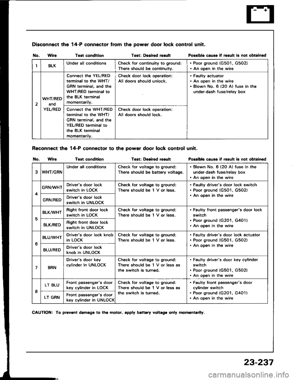
Disconnect the
I{o. WireTost condltlonTest: Dosirsd rosult
Reconnect tho 14-P connector to th6 powor door lock control unit.
t{o. WlroTost conditionTost: Dolir6d r6auh
14-P connector from the power door lock control unit.
Possibls cause if rosult is not obtainod
Posslblo caus6 it rosuh is not obtainod
IBLKUnder all conditionsCheck tor continuity to ground:
There should be continuitv.
. Poor ground (G501 , G502). An open in the wire
2
WHT/RED
and
YEL/RED
Connect the YEL/RED
tarminal to the WHT/
GRN terminal, and the
WHT/REO terminal to
the BLK terminsl
momentarily.
Check door lock oDeration:
All doors should unlock.
Faultv actuator
An open in the wire
Blown No. 6 (2O A) fuse in the
under-dash fuse/relav box
Connect the WHT/RED
terminal to the WHT/
GRN terminal, and the
YEL/RED terminal to
the BLK terminal
momentarilv.
Check door lock ooeration:
All doors should lock.
eWHT/GRN
Under all conditionsCheck tor voltage to ground:
There should be battsry voltage.
. Blown No. 6 {2O A) fuse in the
under-dash fuse/relay box. An open in the wire
4
GRN/WHTDriver's door lock
switch in LOCK
Check for voltagg to ground:
There should be I V or less.
Faultv driver's door lock switch
Poor ground (G501, G5O2)
An oDen in the wireGRN/REDDriver's door lock
switch in UNLOCK
I
BLK/wHTRight tront door lock
switch in LOCK
Check for voltage to ground;
There should bs 1 V or less.
Faulty front passenger's door lock
switch
Poor ground (G201, G4O 1)
An ooen in the wireBLK/REDRight lront door lock
switch in UNLOCK
6
BLUMHTDriver's door lock knob
in LOCK
Check for voltage to ground:
There should be 1 V or less.
Faulty driver's door lock actuator
Poor ground (G501, G5O2)
An ooen in the wireBLU/REDDriver's door lock
knob in UNLOCK
7BRN
Driver's door key
cylinder in UNLOCK
Check for voltage to ground:
There should be 1 V or less as
the switch is turned.
Faulty d,iver's door key cylinder
switch
Poor ground {G501, G5O2l
An open in the wire
I
LT BLUFront passenge.'s doot
key cylinder in LOCK
Check for voltage to ground:
There should be 1 V or less as
the switch is turned.
Faulty tront passenger's door
cylinde. switch
Poo. ground (G201 , G401)
An oDen in the wireLT GRNFront passenger's door
key cylinder in UNLOCK
CAUTION: To provonl damago to tho molor, rpply battory voltago only momrntadly.
23-237
Page 1344 of 1413
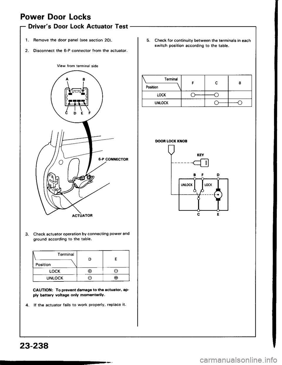
1.
Power Door Locks
Driver's Door Lock Actuator Test
Remove the door panel (see section 20).
Disconnect the 6-P connector from the actuator.
Check actuator operation by connecting power and
ground according to lhe table.
CAUTION: To prevont damago lo tho actualol, ap-
ply battery voltage only momentarily.
lf the actualor fails to work properly, replace it.
Terminal
;;"
---\D
LOCK@o
UNLOCKlJ@
23-238
Terminal
il;----tI
LOCKoo
UNLOCKo--o
5. Check fo. continuity between the terminals in each
switch position according to the table.
DOOR LOCK KI{OB
Page 1345 of 1413
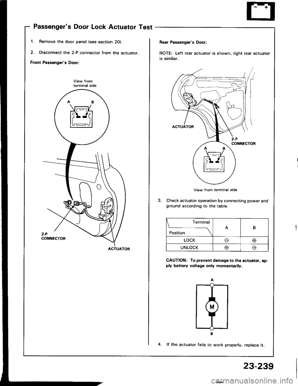
Passenger's Door Lock Actuator Test
1. Remove the door panel (see s
2. Disconnect the 2-P connector
Front Passonger's Door:
terminal side
2-PCONNECTOR
section 20).
r from the actuator.
Rear Passenger's Dool:
NOTE: Left rear actuato, is shown, right rear actuator
is similar.
View from terminal side
Check actuator operation by connecting power andground according to the table.
CAUTION: To prevent damage to the actuator, ap-ply battery voltage only momentarily.
4. It the actuator fails to work properly, replace it.
ACTUATOR
Terminal
Position \
B
LOCK@
UNLOCK@,-,
23-239
Page 1346 of 1413
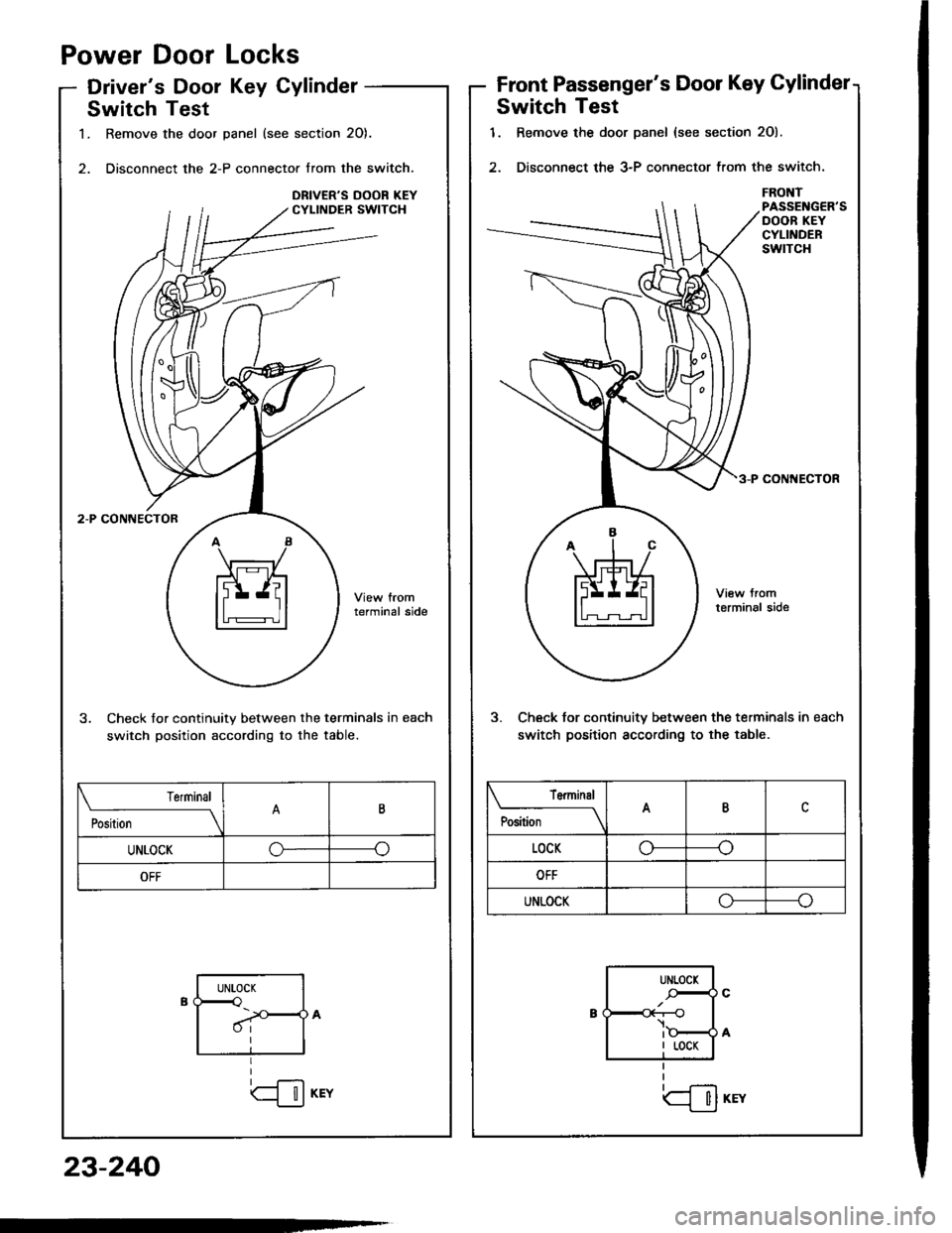
Power
Driver'
Door
s Dool
Locks
Key CylinderFront Passenger's Door Key Gylindet
Switch Test
1. Remove the door Danel {see section 2O).
2. Disconnect the 3-P connector trom the switch.
FRONTPASSENGER'SDOOB KEYCYLINDERswtTcH
coN ECIOR
3. Check tor continuitv between the terminals in each
switch position according to the table.
tfil*rr
Terminal
P""ft;---lABc
LOCKo----o
OFF
UNLOCKo----o
UNLOCK
-r--O
I LOCK
Switch Test
1. Remove the door panel (see section 20).
2. Disconnect the 2-P connector from the switch.
terminal side
3. Check for continuity between the terminals in each
switch position according to the table.
Position
TerminalB
UNLOCKGo
OFF
UNLOCK<
I
23-240
Page 1347 of 1413
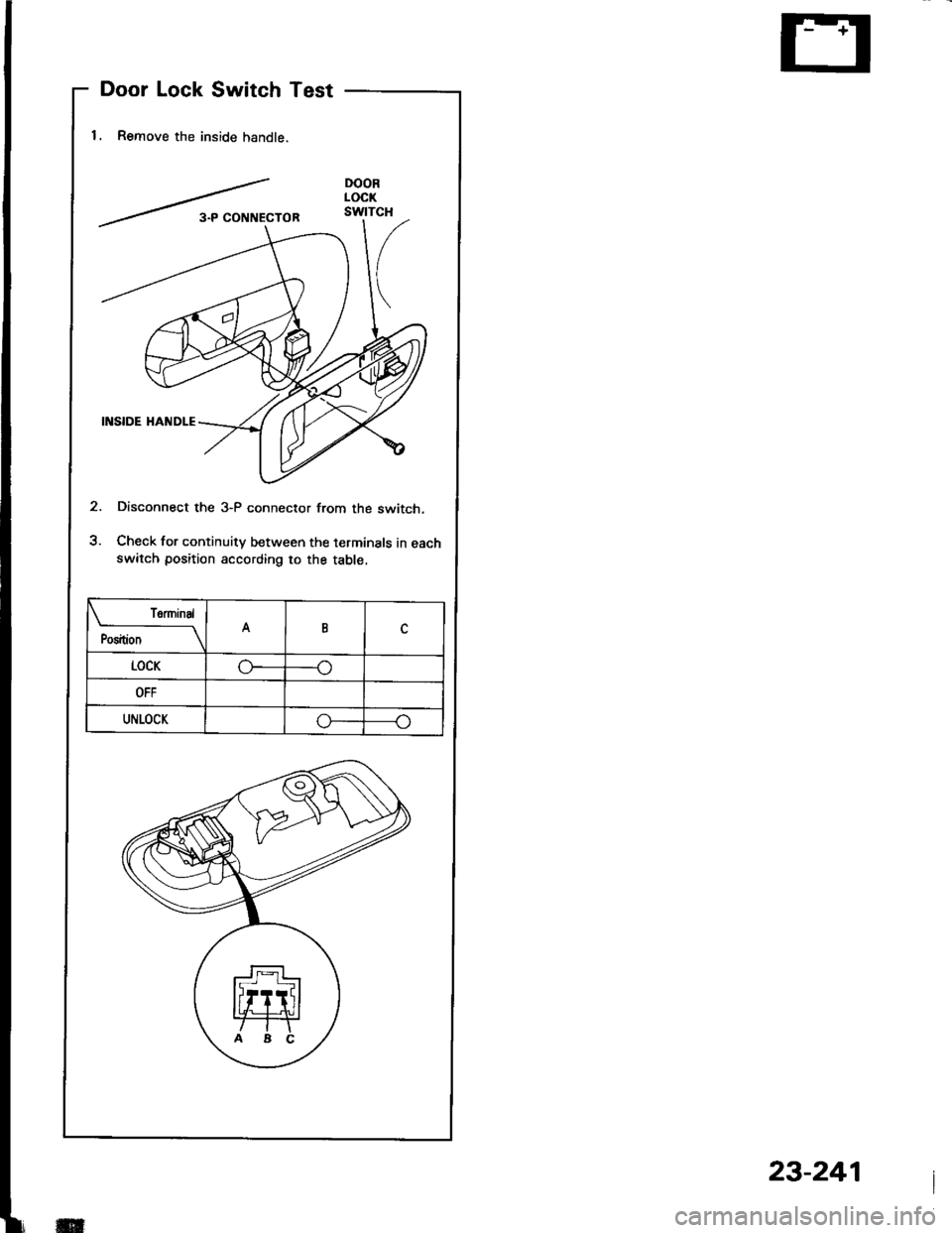
Door Lock Switch Test
1. Remove the inside handle.
Disconnect the 3-P connector from the switch.
Check for continuity between the terminals in eachswitch position according to the table.
termtnal
Position \
nc
LOCKoo
OFF
UNLOCKo
ff
23-241
Page 1352 of 1413
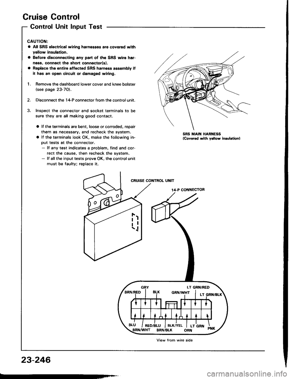
Cruise Control
Control Unit Input Test
CAUTION:
a All SRS olectrical wi ng harnessos are covored with
yellow insulation.
a Botore disconnecting any part of th6 SRS wire har-
neaa, connect the short connoctor(sl.
a Roplace the €ntir€ affectod SRS hamass assembly il
il has an opan circuit or damaged wifng.
1 , Remove the dashboard lower cover and knee bolster(see page 23-70).
2. Disconnect the 14-P connector trom the control unit.
Insoect the connector and socket terminals to be
sure they are all making good contact.
a lf the terminals are bent, loose or corroded, repair
them as necessary, and recheck the system.
a It the terminals look OK, make the following in-
Dut tests at the connector.- It any test indicates a problem, find and cor-
rect the cause. then recheck the svstem.- lf allthe input tesls prove OK, the control unit
must be faulty; replace it.
CRUISE CONTROL UNIT
14-P COI{NECTOR
SRS MAIN HARNESS
23-246
Viow from wire side