connector or terminal HONDA INTEGRA 1994 4.G Workshop Manual
[x] Cancel search | Manufacturer: HONDA, Model Year: 1994, Model line: INTEGRA, Model: HONDA INTEGRA 1994 4.GPages: 1413, PDF Size: 37.94 MB
Page 1357 of 1413
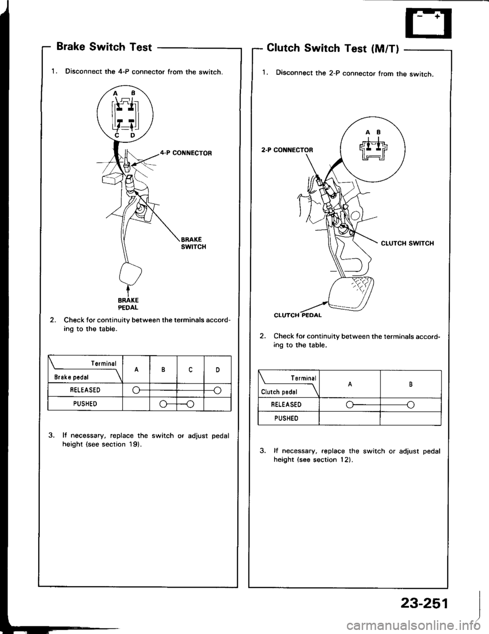
Brake Switch Test
'1. Disconnect the 4-P connector from the switch.
2. Check for continuitv between the terminals accord-
ing to the table.
3. It necessary, replace the switch or adjust pedal
height {see section 19).
Glutch Switch Test (M/T)
I� Disconnect the 2-P connector from the switch,
2. Check {or continuitv between the terminals accord-
ing to the table.
3. lf necessary, replace the switch or adjust pedal
height (see section 12).
I
Terminal
il"*on---\B
BELEASEDo---o
PUSHED-o
| ormtnal
Clutch podal \
RELEASEDoo
PUSHED
23-251
Page 1358 of 1413
Cruise Control
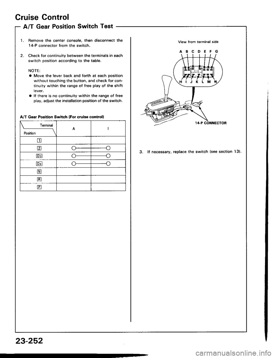
A/T Gear PositionSwitch Test
1.Remove the center console, then disconnect the
14-P connector trom the switch.
Check for continuitv between the terminals in each
switch position according to the table.
NOTE:
a Move the lever back and forth at each position
without touching the button, and check for con-
tinuity within the range of free play ot the shift
lever.
a ll there is no continuity within the range of free
play, adjust the installation position of the switch.
View trom terminal side
ABCDEFG
3. lf necessary, replace the switch (see section 13).
HIJKLM
A/T Gear Position Swhch (For cruis€ control)
Terminal
il;---t
tr
ao
Eo
lu4lo---o
N
B
E
23-252
Page 1359 of 1413
1.
2.
3.
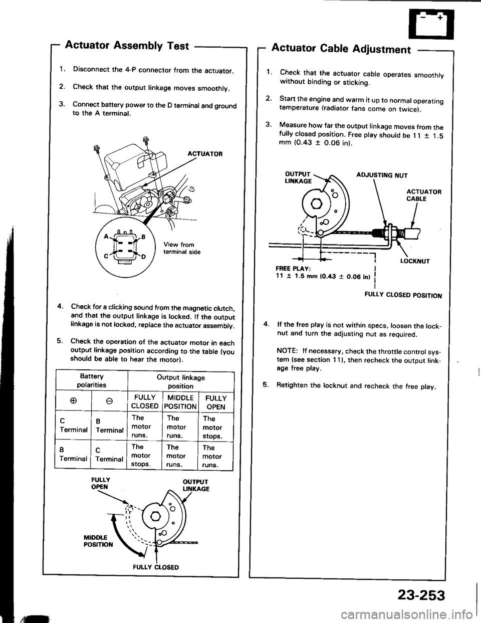
Actuator Assembly Test
Disconnect the 4-P connector from the actuator.
Check that the output linkage moves smoothly.
Connect battery power to the D terminal and groundto the A terminal,
ACTUATOR
Check for I clicking sound trom the magnetic clutch,and that the output linkage is locked. lf the outDutlinkage is not locked, replace the actuator asssmblv.
Check the operation oJ the actuator motor in eachoutput linkago position according to the table (youshould be able to hear the motor).
Actuator Cable Adjustment
Check that the actuator cable operares smoothtvwithout binding or sticking.
Start the engine and warm it up to normaloperatingtemperature (radiator fans come on twicel,
Measure how far the output linkage moves from thefully closed position. Free play should be 1 1 1 1.5mm (O.43 I 0.06 in).
4.
FREE PLAY:1 1 I 1.5 mm (0.43 r 0.06 int
FULLY CLOSED POSITION
4. lf the free play is not within specs, loosen the lock-nut and turn the adjusting nut as required.
NOTE: lf necessary, check the throttle controlsys-tem {see section 1 I }, then recheck the output link-age free play.
5. Retighten the locknut and recheck the free play.
Battery
polaritiesOutput linkage
position
oFULLY
CLOSED
MIDDLE
POStTtON
FULLY
OPEN
Terminal
B
Terminal
The
molor
runs.
The
molor
runs.
The
molor
srops.
I
TerminalTerminal
The
motor
stops.
The
motor
runs.
The
motor
runs.
FULLY CLOSED
,tilr
23-253
Page 1364 of 1413
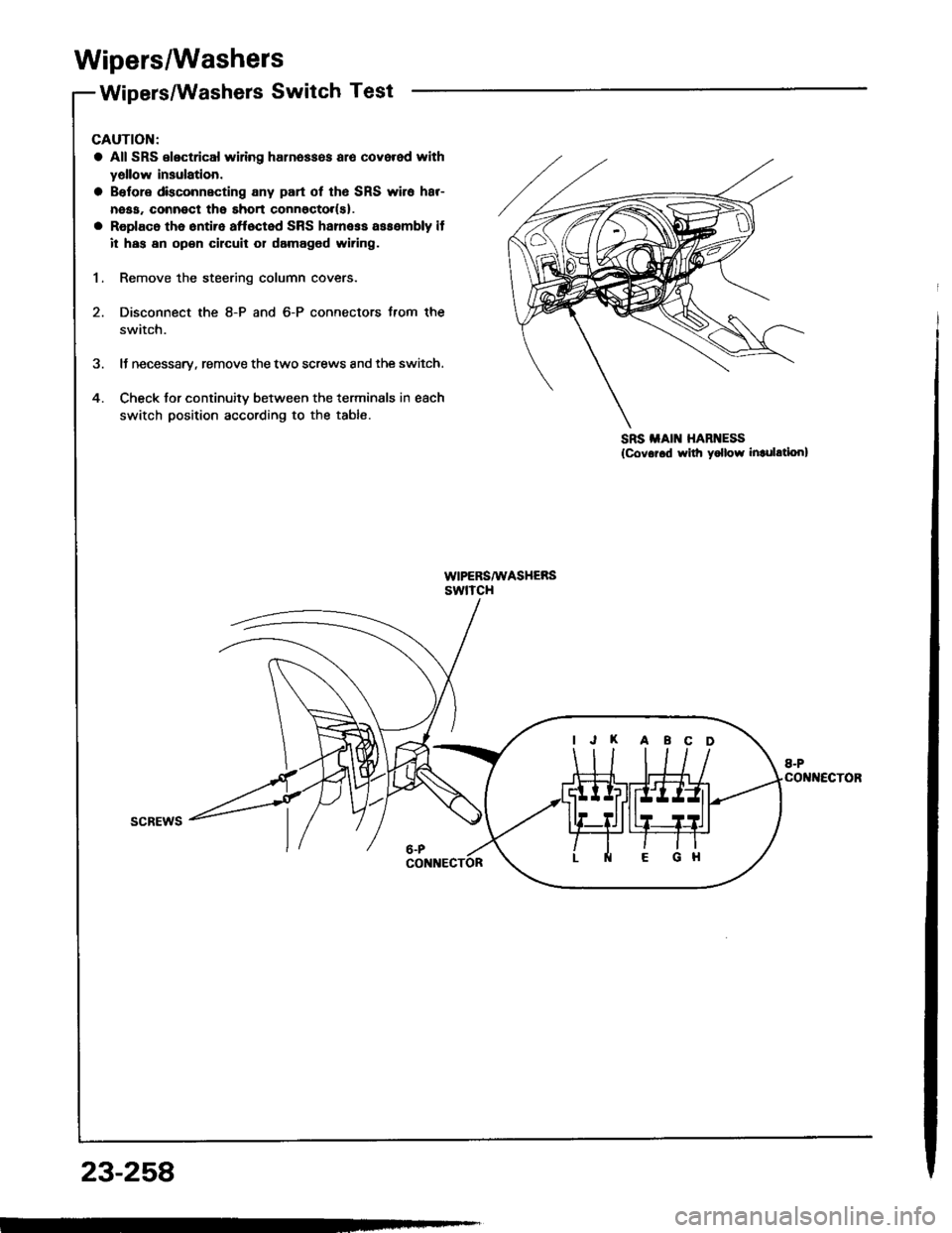
Wipers/Washers
Wipers/Washers Switch Test
5
4
CAUTION:
a All SRS electrical wiring harn6ss6s alo covered with
yellow insulation.
a Belore dkconnecting any part ot th6 SRS wire har-
neaa. connect the short connoctor(sl.
a Replac6 the 6ntire affoctod SRS harness assembly it
it has an open cilcuit 01 damaged wiring.
1. Remove the steering column covers.
2. Disconnect the 8-P and 6-P connectors Jrom the
swatch.
It necessary, remove the two screws and the switch.
Check for continuitv between the terminals in each
switch position according to the table.
scREws
SRS iIAIN HARNESS
{Covor.d rvilh yollow inrulation}
IJK ABCD
23-258
Page 1366 of 1413
Wipers/Washers
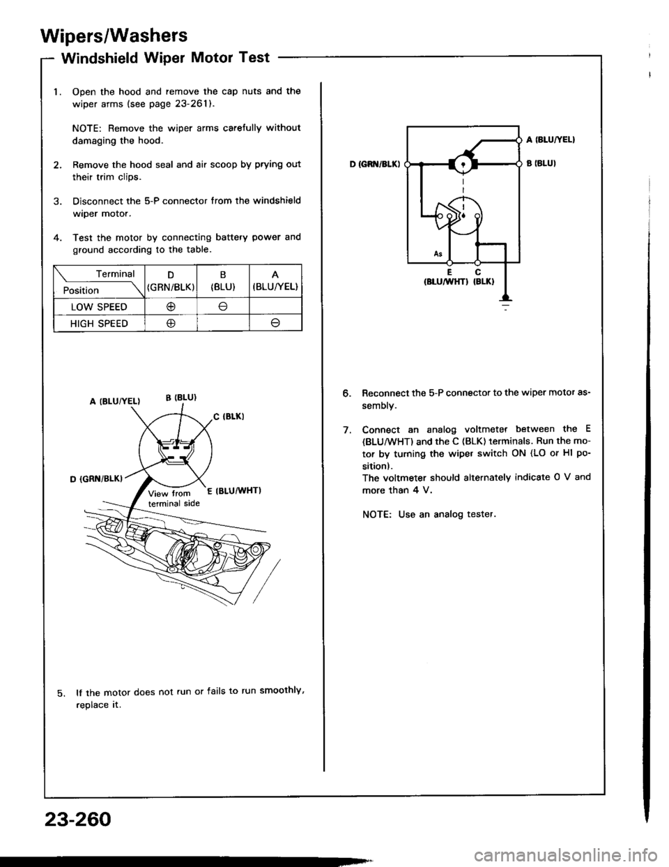
Windshield Wiper Motor Test
Open the hood and remove the cap nuts and the
wiper arms (see page 23-261).
NOTE: Remove the wiper arms carefully without
damaging the hood.
Remove the hood seal and air scoop by prying out
their trim clips.
Disconnect the 5-P connector from the windshield
wiper motor.
Test the motor by connecting battery power and
ground according to the table.
lf the motor does not run or fails to run smoothly,
replace rr.
Terminal
Pi"i,i""---\
D
{GRN/BLK)
B
{8LU)(BLU/YEL}
LOW SPEED@
HIGH SPEED@
23-260
D IGB /BLK)
A SLUTYEL}
B (BLUI
Reconnect the 5-P connector to the wiper motor as-
sembly.
Connect an analog voltmeter between the E
{BLU/wHT) and the C (BLK) terminals. Run the mo-
tor by turning the wipet switch ON (LO or Hl po-
sition).
The voltmeter should alternately indicate O V and
more than 4 V.
NOTE: Use an analog tester.
Page 1368 of 1413
Wipers/Washers
Rear Window Wiper Motor Test-Keal wlnqow wlper |Yloror I esr
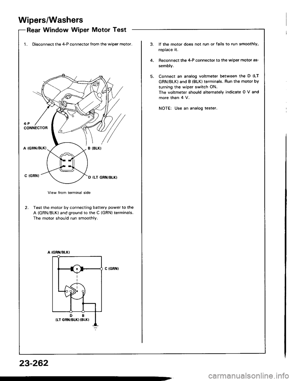
1. Disconnect the 4-P connector from the wiper motor.lf the moto. does not run or fails to tun smoothly,
replace it.
Reconnect the 4-P connector to the wipet motor as-
sembly.
Connect an analog voltmeter between the D (LT
GRN/BLKI and B (BLK) terminals. Run the motor by
turning the wiper switch ON.
The voltmeter should slternately indicate O V and
more than 4 V.
NOT€: Use an analog tester.
4.
4-PCONNECTOR
A (GBN/BLK)
C IGRNI
View trom terminal side
2. Test the motor by connecting battery power to the
A (GRN/BLK) and ground to the C (GRN) terminals.
The motor should run smoothly.
C (GRI{}
23-262
Page 1369 of 1413
l.
2.
1.
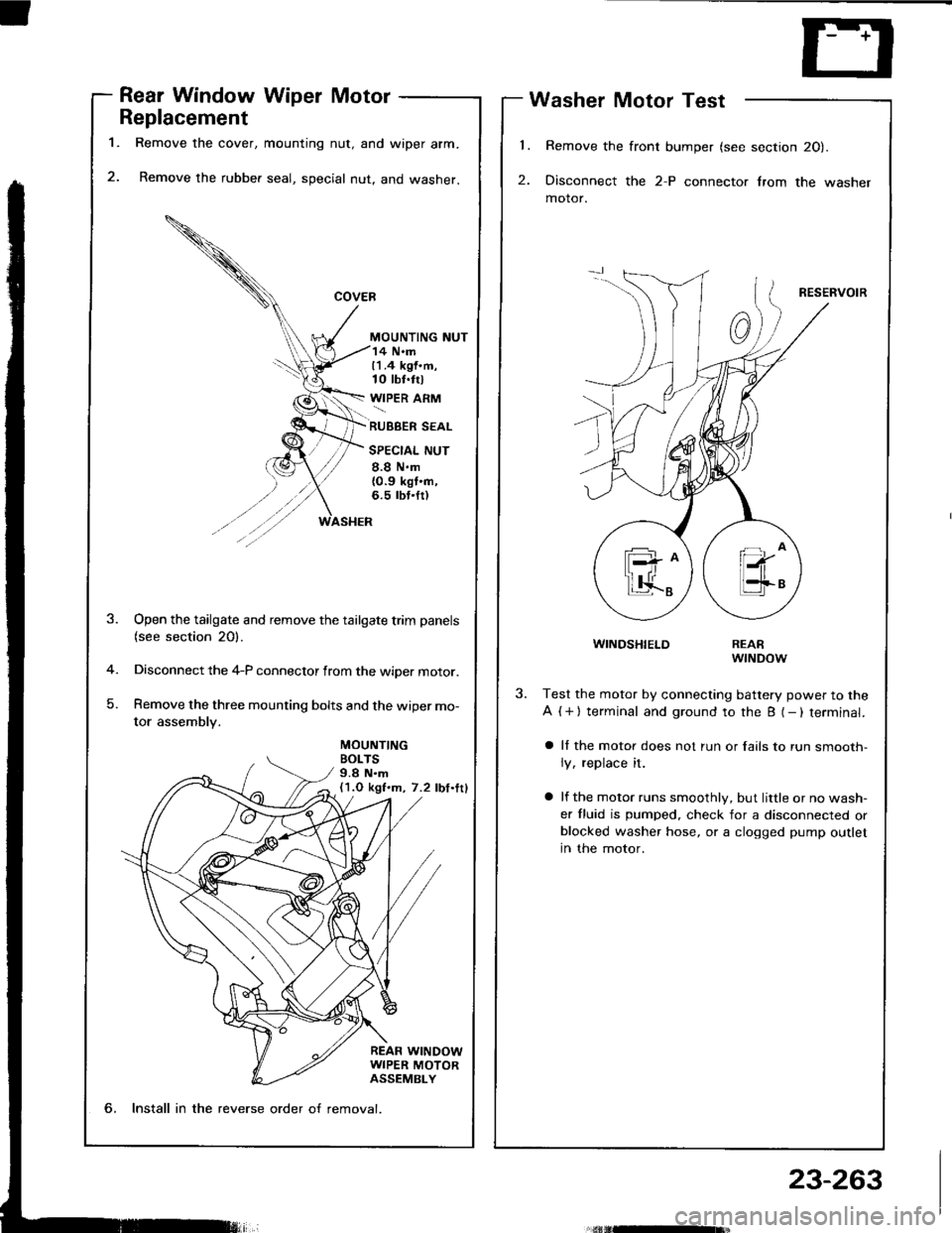
Rear Window Wiper Motor
Replacement
Remove the cover, mounting nut, and wiper arm.
Remove the rubber seal, special nut, and washer.
MOUNTING NUT
Washer Motor Test
Remove the front bumper (see section 20).
Disconnect the 2-P connector lrom the washer
motor.
RESERVOIR
WINDSHIELD
14 N.m11.4 kgf.m,10 tbt.trl
WIPER ARM
RUBBER SEAL
SPECIAL NUT
8.8 N.m{0.9 kgt'n,6.5 rbt.fr)
MOUNTINGBOLTS9.8 N.m(1.O kgf.m, 7.2 lbf.ttl
-4
)
Open the tailgate and remove the tailgate trim panels(see section 20).
Disconnect the 4-P connector from the wiper motor.
Remove the three mounting bolts and the wiper mo-
tor assembly.
REARwrNDow
Test the motor by connecting battery power to the
A ( + ) terminal and ground to the B (- ) terminal.
a ll the motor does not run or fails to run smooth-
ly, replace it.
a lf the motor runs smoothly, but little or no wash-
er fluid is pumped. check for a disconnected orblocked washer hose, or a clogged pump outlet
in the motor.
6, Install in the reverse order o{ removal.
23-263
Page 1381 of 1413
Supplemental Restraint System (SRSI
Troubleshooting
Self-diagnosis Function
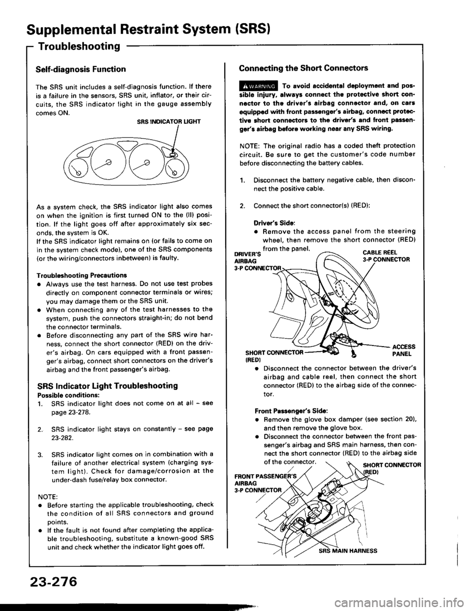
The SRS unit includes a self-diagnosis function. lf there
is a failure in the sensors. SRS unit, inflator, or their cir-
cuits, the SRS indicator light in the gauge sssembly
comes ON.
As a system check, the SRS indicator light also comes
on when the ignition is first turned ON to the (ll) posi-
tion. lf the light goes off after approximately six sec-
onds, the system is OK.
lf the SRS indicator lighr remains on (or fails to come on
in the system check mode), one of the SRS components
(or the wiring/connectors inbetween) is laulty
Troubleshooting Precautions
a Always use the test harness. Do not use test probes
directly on component connector terminals or wires;
you may damage them or the SRS unit.
a When connecting any of the test harnesses to the
system, push the connectors straight-in; do not bend
the connector terminals,
. Before disconnecting any part of the SRS wire har-
ness, connect the shon connector (RED) on the driv-
er's airbag. On cars equipped with a front passen-
ger's airbag, connect short connectors on the driver's
airbag and the front passenger's airbag.
SRS Indicator Light Troubleshooting
Possiblo conditions:
1. SRS indicator light does not come on at all - see
page 23-278.
2. SRS indicator light stays on constantly - see page
23-242.
3. SRS indicator light comes on in combination with a
failure of another electrical system (charging sys-
tem light). Check for damage/corrosion at the
under-dash tuse/relay box connector.
NOTE:
. Before starting the applicable troubleshooting. check
the condition of all SRS connectors and ground
points.
. lf the fault is not found after completing the applica-
ble troubleshooting, substitute a known-good SRS
unit and check whether the indicator light goes off.
23-276
MAIN HARNESS
Connecting the Short Connectors
@ To avoid.ccidental doploymont and pos.
siblo iniury. alway3 connect ths protoctive short con.
noctor to tha driver's airbag connectot and, on caf!
equippod with front passongor's airbag, conncqt Prolac-
tivs ghort connoctors to the d.ivsr's and tront passsn-
gar's airbag before working nsai any SRS wiring.
NOTE: The original radio has a coded theft protection
circuit. Be sure to get the customer's code number
before disconnecting the battery cables,
Disconnect the battery negative cable, then discon-
nect the oositive cable.
Connect the short connector(s) (RED):
Drivsr's Sido:
. Romove the accoss panel trom the steering
wheel, then remove the shon connector (BED)
1.
2.
from the panel.DRIVER'SAIRBAG
CABLE R€EL
3-P
ACCESSPANELSHONT CONNESTOR(REDI
. Disconnect the connector between the driver's
airbag and cable reel, then connect the short
connector {RED} to the airbag side of the connec-
tor.
Front Pas€ngo/s Sido:
. Remove the glove box damper (see section 20),
and then remove the glove box.
. Disconnect the connector between the front pas-
senger's airbag and SRS main harness, then con-
nect the short connector (RED) to the airbag side
of the connector,SHORT CONNECTOR
Page 1385 of 1413
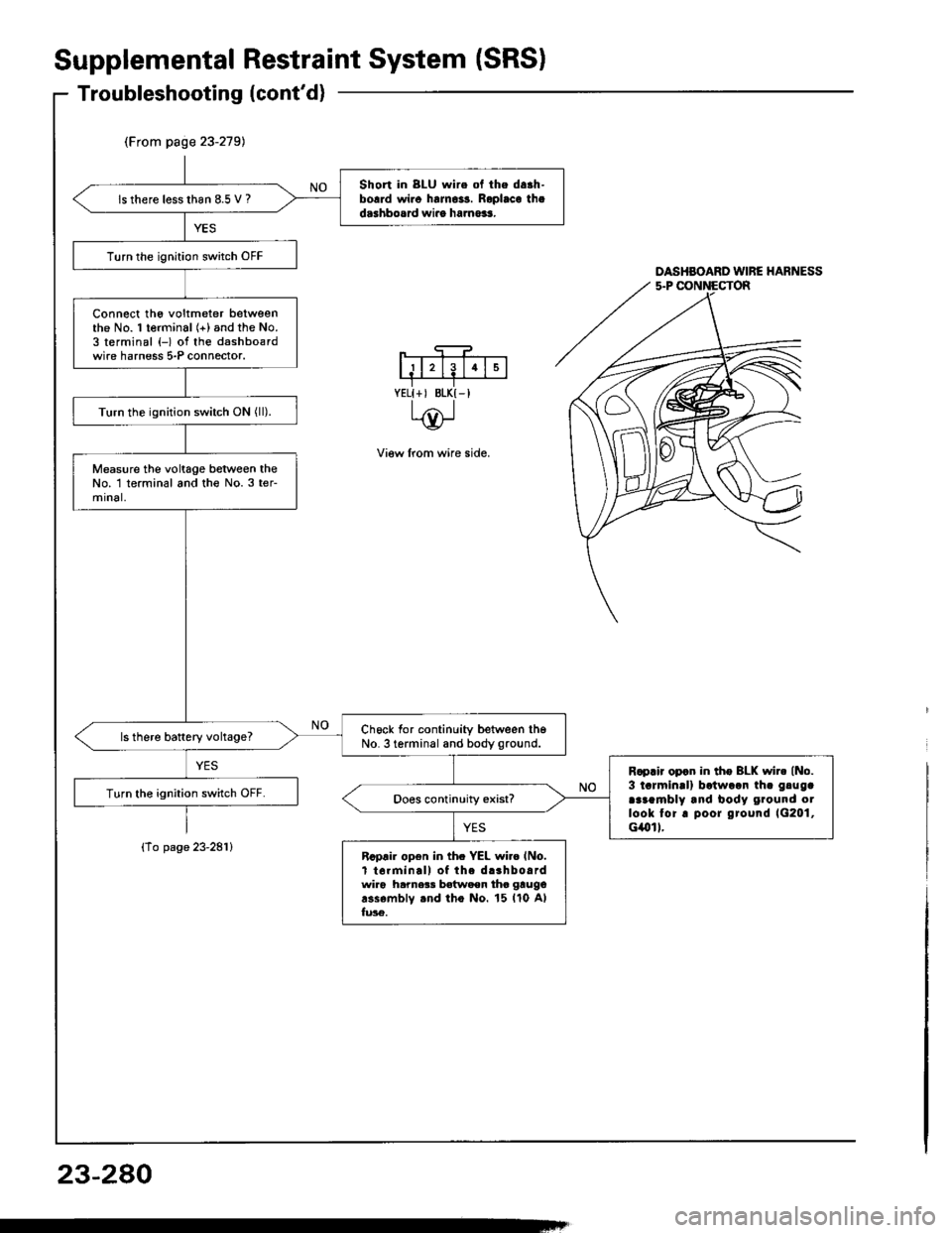
(From page 23-279)
Short in 8LU wire ol the da.h-borrd wi.o halno3s. Roplaca thad.3hbosrd wiro ha.no$.ls there lesslhan 8.5 V ?
Turn the ignition switch OFF
Connect tho voltmeter betweenthe No. 1 terminal (+) and the No.3 terminal (-) of the dashbo€rdwire harness 5-P connector.
Turn the ignition switch ON (ll).
Measure the voltage between theNo. 1 terminal and th€ No.3 ter-mrnal,
Ch6ck for continuity between th6No. 3 terminal and body ground.ls there battery vohage?
R.prir opcn in tho BLK wir. (No.
3 tarmin!l) batwaan th. gluga
araambly and body ground otlook tor. poor ground 1G201,cilol I.
Turn the ignition switch OFF.
Rcprir open in th. YEL wi.o lNo.t t6rminall of the d.3hbo.rdwir6 hamer! batwaen tho gtugo
r3s6mblv rnd tho No. 15 ll0 Alfu36.
Supplemental
Troubleshooting(cont'd)
{To page 23-281}
RestraintSystem (SRSI
DASHBOARD WIRE HARNESS
View lrom wire side.
YELI+, BLK{-I
23-280
Page 1386 of 1413
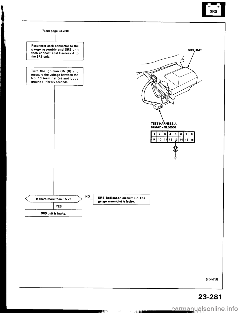
(From page 23-280)
Reconnect each connector to thegauge assembly and SRS unitthen connect Tgst Harness A tothe SRS unit.
Turn the ignirion ON 0l) andmoasure th€ voltage betwegn theNo. 13 terminal (+) and bodyground (-) tor six seconds.
SBS indic.tor circqit {in th.e.ug. r.t mblv, i. hulty,ls th€r6 more than 8.5 V?
TEST HARNESS A07MAZ - S!IX)s{X'
48
910Itl213l41516
23-2a1
,;l tflEt$ r'