lock HONDA INTEGRA 1994 4.G Workshop Manual
[x] Cancel search | Manufacturer: HONDA, Model Year: 1994, Model line: INTEGRA, Model: HONDA INTEGRA 1994 4.GPages: 1413, PDF Size: 37.94 MB
Page 602 of 1413
Driveshafts
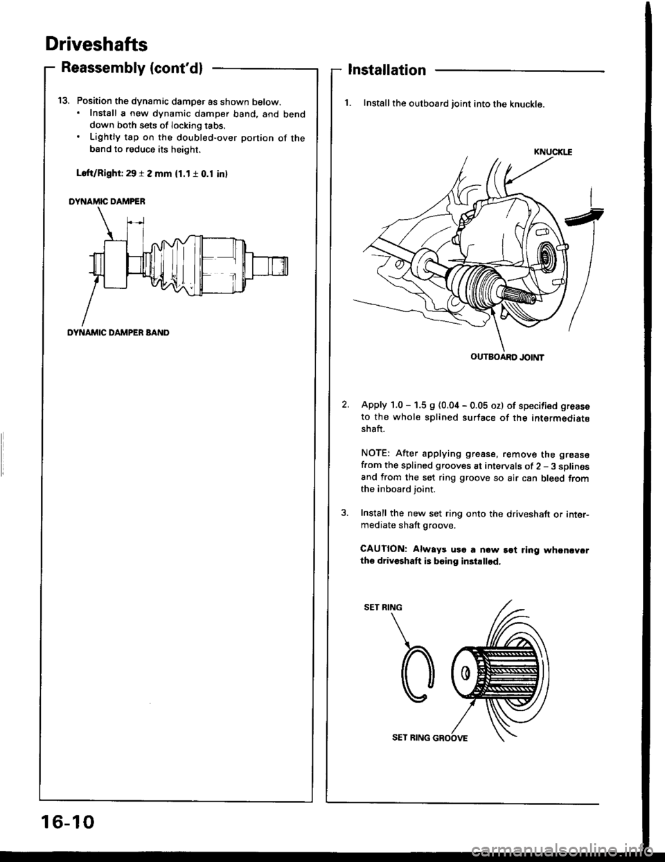
Position the dynamic damper as shown below.. Install a new dynamic damper band. and benddown both sets of locking tabs.
Lightly tap on the doubl€d-over ponion of theband to reduce its height,
Loft/Right 29 r 2 mm (1.1 r 0.1 inl
DYNAMIC DAMPER
t5.
Reassembly (cont'dl
DYNAMIC DAMPER BANO
Installation
1. Install the outboard joint into the knuckle.
KNUCIGE
Apply 1.0 - 1.5 s (0.04 - 0.05 oz) of specified groase
to the whole splined surtace of the intermediatsshaft.
NOTE: After applying grease, remove the grsase
f.om the splined grooves at intervals of 2 - 3 sDlinesand from the set ring groove so air can bleed fromthe inboard joint.
Install the new set ring onto the driveshaft or inter-mediate shaft groove.
CAUTION: Always uso a now sot ring whcncycrtho driveshaft is boing in3tallod.
RING
b
OUTBOARD JOINT
16-10
SET RING GROOVE
Page 603 of 1413
5.
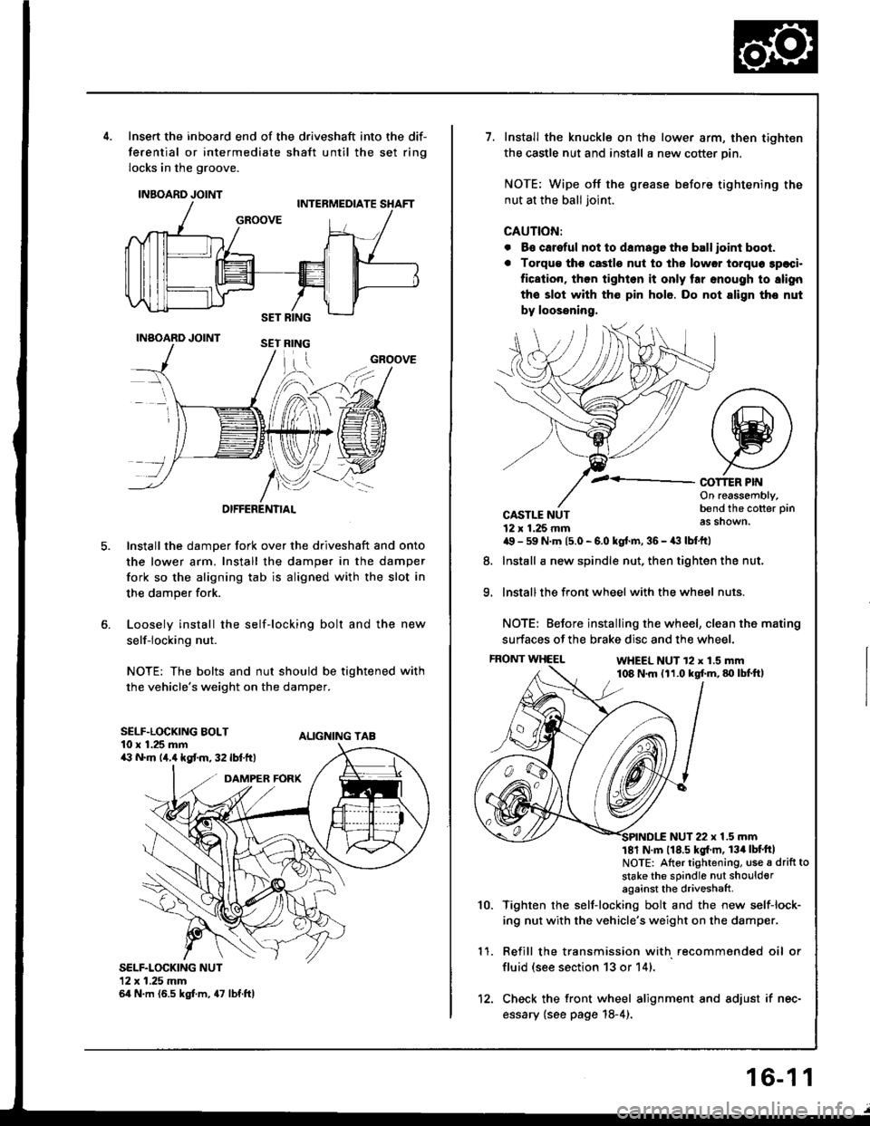
Insert the inboard end of the driveshaft into the dif-
ferential or intermediate shaft until the set ring
locks in the groove.
INBOARD JOINT
INAOARD JOINT
OIFFERENTIAL
Install the damper fork over the driveshaft and onto
the lower arm. Install the damper in the damper
fork so the aligning tab is aligned with the slot in
the damper fork.
Loosely install the self-locking bolt and the new
self-locking nut.
NOTE: The bolts and nut should be tightened with
the vehicle's weight on the damper.
ALIGNING TAB
SELF.LOCKING NUT12x 1.25 mm64 N.m (6.5 kgt m, 47 lbf.ftl
GROOVE
SELF.LOCKING BOLT10 x 1.25 mma:' N.m lir,4 kgt m, 32 lbf.ftt
1.Install the knuckle on the lower arm, then tighten
the castle nut and install a new cotter pin.
NOTE: Wipe off the grease before tightening the
nut at the ball joint.
CAUTION:
. B€ careful not to damago tho ball ioint boot.
. Torqu€ tho castle nut to ths lower torquo 3paci.
fication, then tighlon it only tar snough to slign
the slot with th€ pin hole. Do not align tho nut
by loossning,
COT1ER PIf{On reassembly,bend the cotter pin
as shown.
9.
CASTLE NUT12 x 1.25 rnma9 - 59 N.m 15.0 - 6.0 kgt.m, 36 - a:t lbtftl
Install a new spindle nut, then tighten the nut,
Install the front wheel with the wheel nuts.
NOTE: Before installing the wheel, clean the mating
surfaces of the brake disc and the wheel.
FRONT WHEELWHEEL NUT 12 x 1.5 mm108 N.m (11.0 kgf.m,80lbtft,
8.
1 '�I.
10.
NUT 22 x 1.5 mm181 N m 118.5 kgl'm, 134lbt'ftlNOTE: Altor tightening, use a drift to
stake the sPindle nut shoulderagainst the driveshaft
Tighten rhe self-locking bolt and the new self-lock-
ing nut with the vehicle's weight on the damper.
Refill the transmission with recommended oil or
fluid (see section 13 or 14).
Check the front wheel alignment and adjust if nec-
essary {see page 18-4).
12.
16-1 1
Page 609 of 1413
I
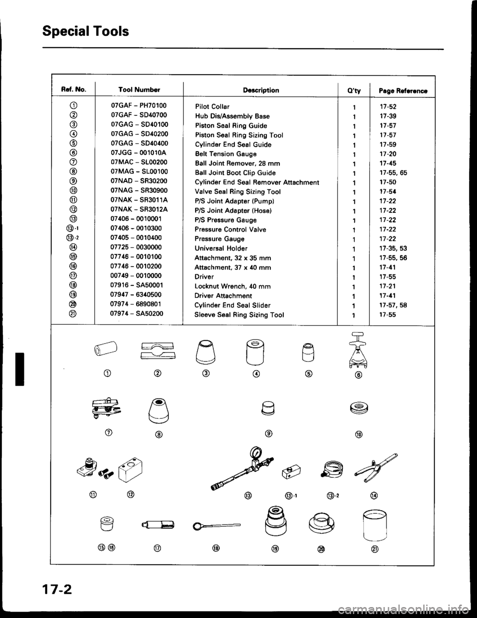
Rcf. No. I Tool Numb€lDcscriptionO'ty I P!9. Relrrrncc
o
@
@(t
@
@
o
@
@
@
@
@
@
@.r
@-2
@
@
@
@
@
@
@
@
07GAF - PH70100
07GAF - SD40700
07GAG - SD40100
07GAG - SD40200
07GAG - SD40400
07JGG - 0010104
07MAC - 5100200
07MAG - 5100100
07NAD - SR30200
07NAG - SR30900
OTNAK - SR3O11A
OTNAK - SR3O12A
07406 - 0010001
07406 - 0010300
07405 - 0010400
07725 - 0030000
07746 - 0010100
07746 - 0010200
007i$ - 0010000
07916 - SA50001
07947 - 6340500
07974 - 6890801
0797,1 - SA50200
Pilot Collar
Hub DivAssembly Base
Piston Seal Ring Guide
Piston Seal Ring Sizing Tool
Cylinde. End Seal cuide
Belt Tension Gauge
Ball Joint Remover, 28 mm
Ball Joint Boot Clip Guide
Cylinder End Seal Remover Attachment
Valve Ssal Ring Sizing Tool
P/S Joint Adapter (Pump)
P/S Joint Adapter (Hos6)
P/S Pressure Gsuge
Pressure Control Valve
Pressure Gauge
Universal Holder
Attachment, 32 x 35 mm
Attachment, 37 x 40 mm
Driver
Locknut Wrench, i[0 mm
Driver Anachment
Cylinder End Seal Slider
Sleeve Sesl Ring Sizing Tool
1
I
1
1
1
1
1
1
1'I
1
1
1
1
1
1'l
1
I
1
1
1
1
'17 -52
17-39
17 -57
17 -57
17-EO
17 -20't7 -15
17-50
17-5{
17 -22
17 -22't1-22
17 -22
17-35, 53
17-55, 56
17 -1'l
t7-55
17 -2'l
17 -11
17-57,58
17-55
aL2
o
re
F--,'---l
@
g
t.-,
@
q
o
etl
TJ
@
a\,
@
e
U
\v
o
I
@
,h z6)
@
@-r
6
w
@,2
^dN
v
@
@
16)
Y
@@
lx:__E
@
@:
@@
17-2
Page 619 of 1413
Troubleshooting
General Troubleshooting {cont'd}
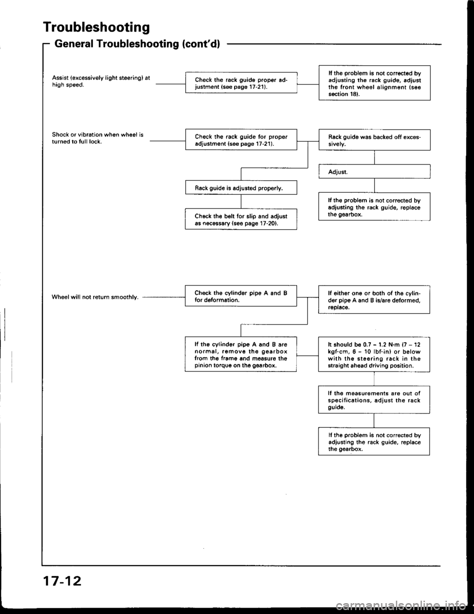
Assist (excessively light steering) athigh speed.
Shock or vibration when wheel isturned to tull lock.
Wheelwill not return smoolhly.
ll the problem is not corrected byadjusting th6 rack g!ide. adjustthe front wheel alignment (see
section 18).
Check the rack guido proper ad'justment (see pago 17-21).
Check the rack guide tor properadjustment (ses psge 17-21).
Rack guide is adjusted prop€rly.
lf th€ problem is not correct€d byadiusting the rack guide, roplacethe gesrbox.Ch6ck the belt tor slip and adjustas nocessary (see page 17-20).
lf oither one or both of the cylin-der pip€ A and B is/are deformed,rsplace,
lf the cylinder pip6 A and B arenormal, remove the gearboxfrom th€ f.ame and mossure thepinion torqug on the gearbox.
It should be 0.7 - 1.2 N.m {7 - 12kgf.cm, 6 - 10 lbf.in) or belowwith the sleering rack in thestraight ahead driving position.
lf lhe measurem€nts are out ofspecilications. adjust the rackguid6.
ll ihe problem is not corrected byadjusting the rack guide, replaceihe gearbox.
17-12
Page 625 of 1413
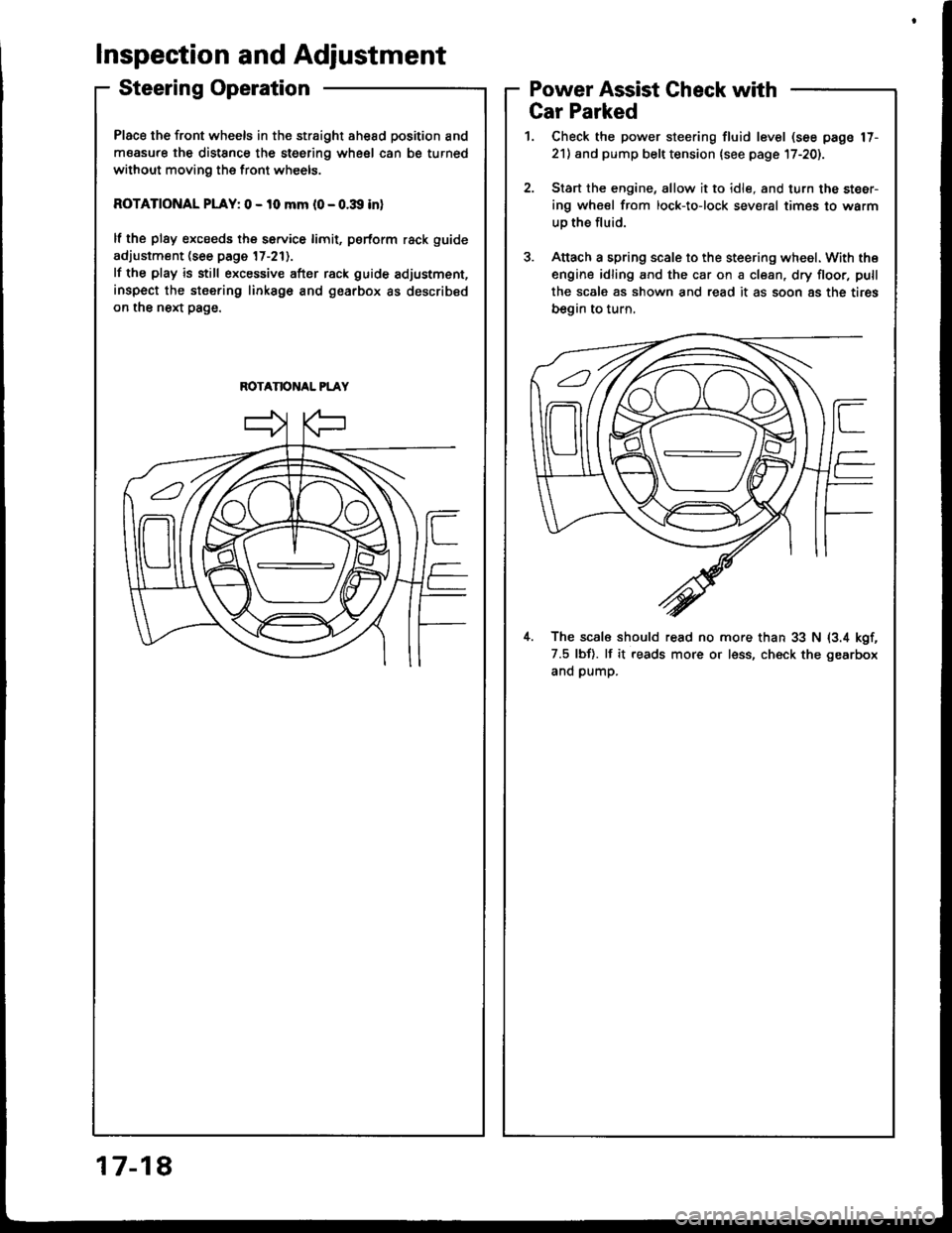
Place the front wheels in the straight ahesd position and
measure the distSnce the steering wheel can be turned
without moving the front wheels.
ROTATIONAL PLAY: 0 - 10 mm l0 - o.:Xl inl
lf the plsy excseds the service limit, psrform rack guide
adjustment (see page 17-211.
lf the play is still excessive after rack guide adjustment,
inspect the stsering linksgo and gearbox as described
on the next page.
ROTANONAL PLAY
Inspection and Adjustment
Steering OperationPower Assist Gheck with
817-1
Gar Parked
1. Check the power steering fluid level (see page 17-
21) and pump belt tension lsee page l7-20).
2.Start the engine, allow it to idle, and turn the steer-
ing wheel from lock-to-lock sev€ral times to warm
uo the fluid.
Attach a spring scale to the steering wheel. With the
engine idling and the car on a clean, dry floor, pull
the scale as shown and read it as soon 8s the tires
begin to turn,
il. The scal6 should read no more than 33 N (3.4 kgf,
7.5 lbf). lf it reads more or less, ch€ck the gearbox
and pump.
Page 626 of 1413
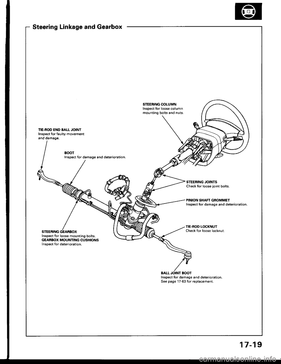
Steering Linkage and Gearbox
STEERING COLUMNlnsoect tor loose columnmounting bolts and nuts.
BOOTInspect f6r damage and deterior6tion.
STEERING JOINTSCheck tor loose joint bolts.
PINION SHAFT GROMMETInspect lor damage and deterioration.
STEERING
TIE.ROD LOCKNUTCheck for loose locknut.
Inspect lor loose mounting bolts.GEARBOX MOUNTING CUSHIONSInspect for deterioration.
BALL JOINT BOOTInspect tor damage and deterioration.See psge 17-63 for replacement.
17-19
Page 627 of 1413
Inspection and Adjustment
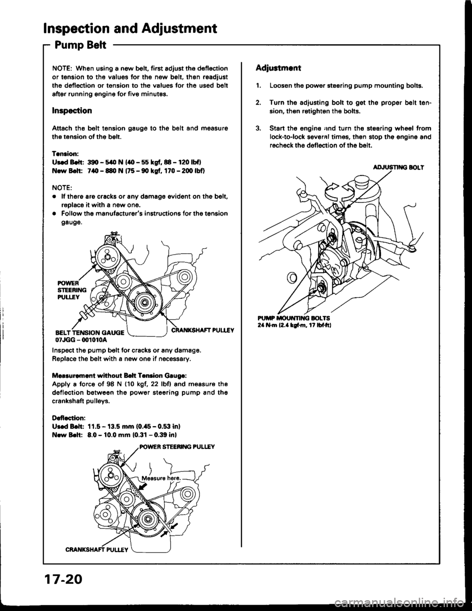
Pump Belt
NOTE: When using a new b€li, first adiust the deflection
or t€naion to the values for the new belt, thsn readiust
ths deflection or tension to the values tor the used b€lt
after running sngine for five minutss.
lnspoction
Attach th€ belt tonsion gauge to th6 belt and measure
ths tension of the bslt.
Tanaion:
U3.d Brft: 391, - 5/O N (lO - 55 kgf, 88 - r20 |bf)
Ncw Bch: 7aO - 89, N (75 - 90 kgt, 170 - 20O lbO
NOTE:
. lf thsre are cracks or any damage evident on the belt,
raplaca it with a now ono.
. Follow the manufacturer's insructions for the tonsion
g8uge.
PUII"EY
07JGG - 00r0r0a
Inspect the pump belt for cracks or any damage.
Replace the belt with a new one if nec€ssary.
Mc!3uramrnl without Bch Tcntion Grugr:
Apply a torce of 98 N (10 kgl, 22 lbll and measure ths
deflection between tho power ste€rin9 pump and tho
crankshaft pulleys.
Daffaction:
U:ed Bch: 11.5- 13.5 mm (0.,t5-0.53 inl
Nlw Brh: 8.0 - 10.0 mm (0.31 - 0.39 inl
here,
17-20
Adiu3tmant
1, Loosen the power stesring pump mounting bolts.
2. Turn ths adiusting bolt to gst the propor bolt ten-
sion, then rstighten the bolts.
3, Start ths €ngine and turn the steering wheel trom
lock-tolock s€veral times, then stop the engino and
recheck ths deflection of the belt.
AD'USN G BOLT
Page 628 of 1413
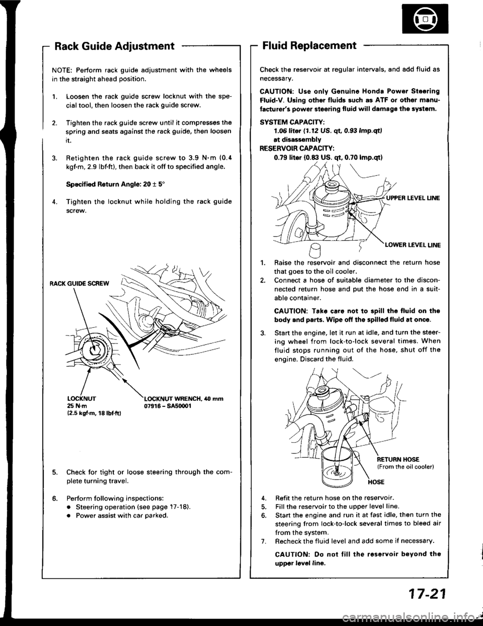
NOTE: Perform rack guide adjustment with the wheels
in the straight ahead position.
Loosen the rack guide screw locknut with the spe-
cialtool, then loosen the rack guide screw.
Tighten the rack guide screw until it compresses the
spring and seats against the .ack guide, then loosen
it.
Retighten the rack guide screw to 3.9 N.m {0.4
kgf'm, 2.9 lbf.ft), then back it off to specified angle.
Specified R6turn Angle: 20 t 5"
Tighten the locknut while holding the rack guide
screw.
1.
6.
RACK GUIDE SCREW
25 N.m12.5 kgf.m, 18lbtftl
L(rcKNUT WRENCH, 40 mm07916 - SAs(xtOl
Check for tight or loose steering through the com-
plete turning travel.
Perform following inspections:
. Steering operation (see page 17-18).
. Power assist with car parked.
Check the reservoir at regular intervals. and add fluid as
necessary.
GAUTION: Use only Genuine Honda Power Stosring
Fluid-V. Using othsr fluids such as ATF or other manu-
facturer's power stoering fluid will damags ths systcm,
SYSTEM CAPACITY:
LO6 litor (1.12 US. qt, 0.93 lmp.qtl
at disasssmbly
RESERVOIR CAPACITY:
0.79 lit6r (0.8:l US. qt, 0.70 lmp.qt)
UPPER LEVEL UNE
LOWER LEVEL LINE
,l
Raise the reservoir and disconnect the return hose
that goes to the oil cooler.
Connect a hose of suitable diameter to the discon-
nected return hose and put the hose end in a suit-
able container.
CAUTION: Tako caro not to 3pill tho tluid on tho
body and parts. Wipe off the spilled tluid at onqe.
Start the engine. let it run at idle. and turn the steer-
ing wheel from lock-to-lock several times. When
fluid stops running out of the hose, shut off the
engine. Discard the fluid,
Refit the return hose on the reservor.
Fill the reservoir to the uDoer level line.
Start the engine and run it at fast idle, then turn the
steering from lock-to-lock several times to bleed air
f.om the system.
Recheck the fluid level and add some if necessary.
CAUTION: Do not lill the roservoir beyond tho
uppgr lovel line.
7.
Page 629 of 1413
lnspection and Adjustment
Pump Pressure Check
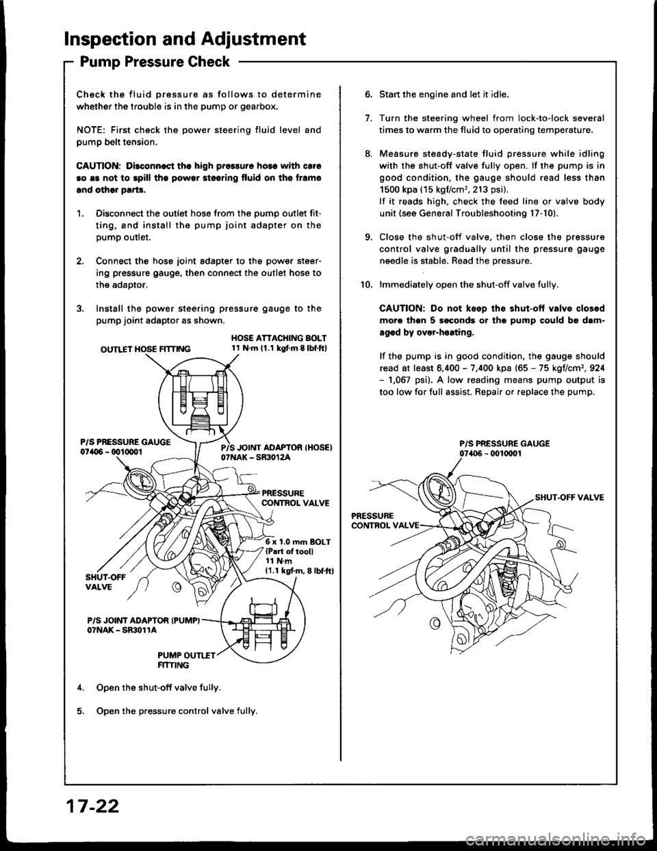
Check the fluid pressure as follows to determine
whether the trouble is in the pump or gearbox.
NOTE: First check the power steering fluid level and
pump belt tension,
CAUnON: Dilconn€st the high pros3uro ho3s with cale
!o e3 not to spill tho powor stooring fluid on th6 lramo
lnd olhor parG.
1. Disconnect the outlet hose from the oumo outlet fit-
ting, 8nd install the pump joint adapter on the
pump outlet.
2, Connect the hose joint sdapter to the power steer-
ing pressure gauge, then connect the outlet hose to
the adaotor.
3. Instsll the power steering pressure gauge to the
pump joint adaptor as shown.
OUTLET HOSE FlTnNG
HOSE ATTACHING BOLT1l Nm11.1 kg{ m 8lbf.ftl
6 x 1.0 m.n BOLT{P!rt of tooll11 N.m11.1 kgtm,8lbf.ftl
P/S JOINT ADAPTOR IPUMPIo?NAK - SmolrA
PUMP OUTI.TTFITIING
Open the shut-off valve fully.
Open the pressure control valve fully.
17 -22
1.
Start the engine and let it idle.
Turn the stee.ing wheel from lock-to-lock several
times to warm the fluid to operating temperature.
Measure steady-state fluid pressure while idling
with the shut-off valve fully open. lf the pump is in
good condition, the gauge should read less than
1500 kpa (15 kgf/cm,,213 psi).
lf it reads high, check the feed line or valve body
unit (see General Troubleshooting l7-10).
Close the shut-off valve. then close the pressure
control valve gradually until the pressure gauge
needle is stabl6, Read the pressure.
lmmediately open the shut-off valve fully.
CAUTION: Do not keep the shut-ott valvs closod
moro thgn 5 soconds or th9 pump could b6 dam"
agod by over-h6ating,
lf the pump is in good condition, the gauge should
read at least 6.400 - 7,400 kpa (65 - 75 kgIlcm,,924- 1,067 psi). A low reading means pump output is
too low for full assist. Repair or replace the pump.
10.
P/S PRESSURE GAUGE
Page 633 of 1413
Steering Wheel
Installation
Airbag installation
CAUTION:
. B€fore inrtalling the stooring wheel, align tho front
who6l3 etraight ahead.
. Bo sure to install the harness wires so that thGy are
not pinched or intorfsring with othor car parts.
. Do not roplace thc original stsoring wheel with any
othor design. since it will maks it impo$ibla to prop-
erly install the airbag. {Only use genuine HONDA
replscomont parts)
. After rols3embly. confirm thai the whoels are still
straight ahoad 8nd that steoring wheel spoke anglo
is correct. lf minor spoke anglo adiustment is noc€s-
srry, do so qnly by adlustment ol th€ tie-rods, not byromoving and repositioning the steering wh€€|.
@ contirm ihat the airbag assombly is
socurely attachsd to the stooring wheel; oth€rwise,
scvoro porsonal iniury could r€sult during airbag
doploym6nt.
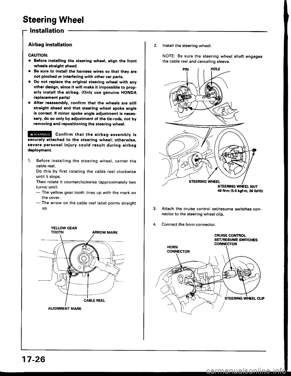
1. Before installing the steering wheel, center the
cable reel.
Do this by tirst rotating the cable reel clockwise
until it stoos.
Then rotate it counterclockwise (approximately two
turnsl until:- The yellow gear tooth lines up with the mark on
the cover.- The arrow on the cable reel label points straight
UD.
YELI-OW GEAR
ALIGNMENT MARK
17-26
2. Install the steering wheel.
NOTE: Be sure the steering wheel shaft engages
the cable reel and canceling sleeve.
a9 N.m (5.0 ksf'm,36 lbf.ftl
Attach the cruise control sevresume switch€s con-nector to the steering wheel clip.
Connect ihe horn connector.
CRUISE CONTROLSET/NESUME SWITCHESCONNECTOR