lock HONDA INTEGRA 1994 4.G Workshop Manual
[x] Cancel search | Manufacturer: HONDA, Model Year: 1994, Model line: INTEGRA, Model: HONDA INTEGRA 1994 4.GPages: 1413, PDF Size: 37.94 MB
Page 990 of 1413
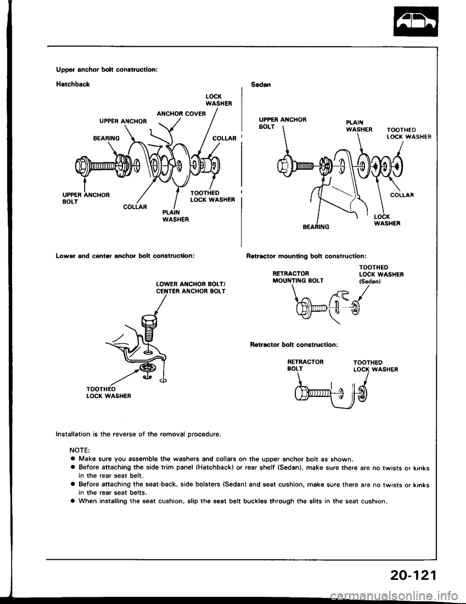
Uppo. anchor bolt construction:
Hatchback
ANCHOR COVERUPPER ANCHOB
BEARING
COLLAR
Lower and cantol ancho. bolt conatluction:
LOWEB AI{CHOR BOLT/ANCHOR BOLT
Sedan
Rotracto. mounting bolt construclion:
RETRACTOR
LOCKWASHER
COLLAR
TOOTHEDLOCK WASHEN
TOOTHEDLOCK WASHER
TOOTHEDLOCK WASHER
TOOTHEOLOCK WASHER
UPPER AI{CHOR
WASHER
MOUNTING BOLT {Sedanl\/ /{- tr- J
l$t".,-,fu l-n(tYlf- u tY
\
Rotractor bolt construction:
RETRACTORAOLT
b'ryd
Installation is the reverse of the removal procedure.
NOTE:
a Make sure you assemble the washers and collars on the upper anchor bolt as shown.a Before attaching the side trim panel (Hatchbackl or rear shelf (Sedan), make sure there are no twists or kinksin the rear seat belt.
a Before attaching the seat-back, side bolsters {Sedan) and seat cushion, make sure there are no twisls or kinksin the rear seat belts.
a When instslling the seat cushion, slip the seat belt buckles through the slits in the seat cushion.
20-121
Page 991 of 1413
Seat Belts
lnspection
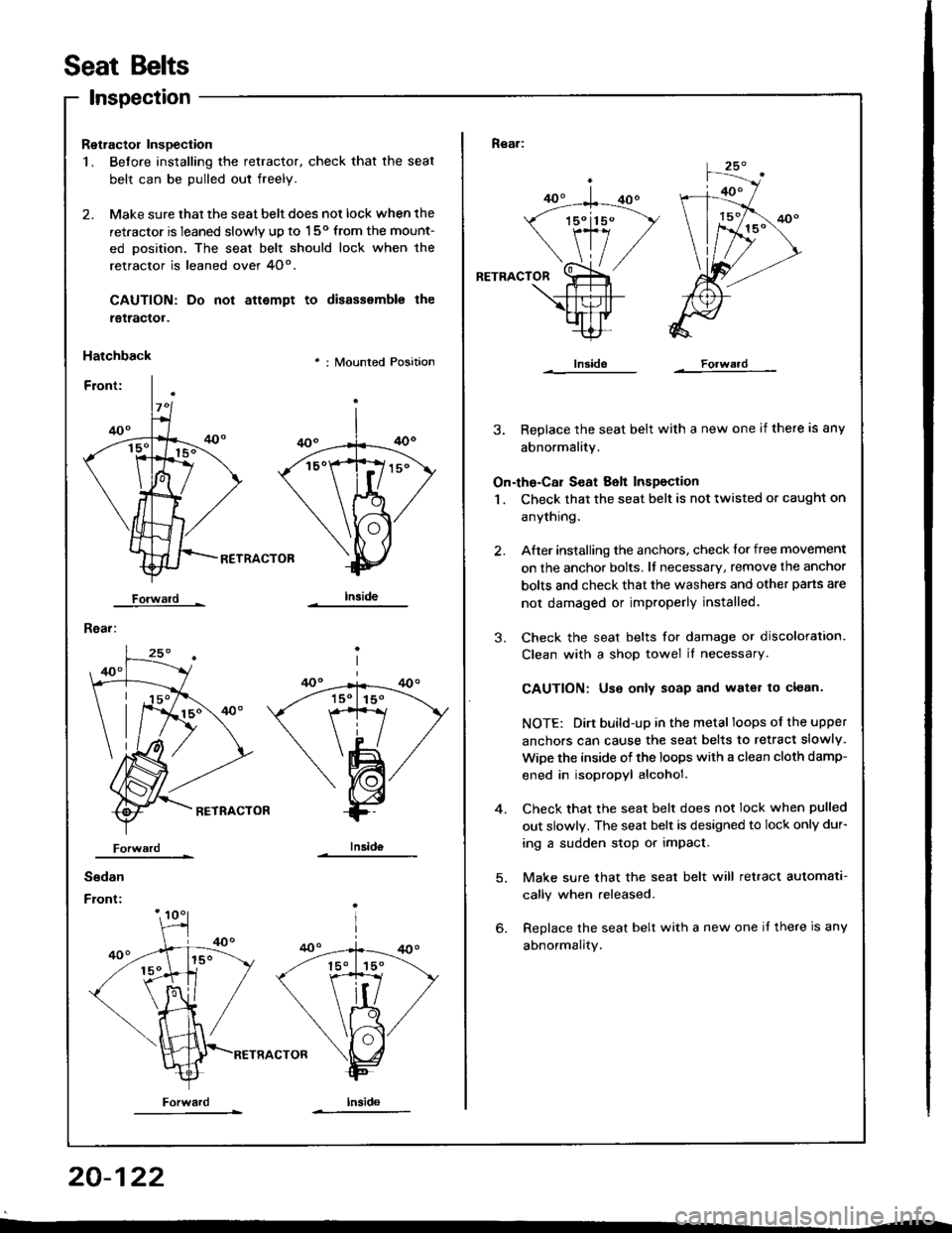
Retractol InsDection
1. Before installing the retractor, check that the seat
belt can be pulled out freely.
2. Make sure that the seat belt does not lock when the
retractor is leaned slowly up to 150 from the mount-
ed oosition. The seal belt should lock when the
retractor is leaned over 4O".
CAUTION: Do
tgtractol.
Hatchback
Forwald -
Rear:
not attempt to disassemble the
' : Mounted Position
RETRACTOB
Iniid6
Sedan
Front:
Forwardlnsido
Forward
Rear:
RETRACTOR
3. Replace the seat belt with a new one if there is any
abnormality.
On-the-Cal S€at Belt Inspection
1 . Check that the seat belt is not twisted or caught on
anythrng.
After installing the anchors, check lor free movement
on the anchor bolts. lf necessary, remove the anchor
bolts and check that the washers and other pans are
not damaged or improperly installed.
Check the seat belts for damage or discoloration.
Clean with a shop towel iI necessary.
CAUTION: Use only soap and water to clean.
NOTE: Dirt build-up in the metal loops of the upper
anchors can cause the seat belts to retract slowly.
WiDe the inside of the loops with a clean cloth damp-
ened in isopropyl alcohol.
Check that the seat belt does not lock when pulled
out slowly. The seat belt is designed to lock only dur-
ing a sudden stop or impact.
Make sure that the seat belt will retract automata-
cally when released.
Replace the seat belt with a new one it there is any
abnormality.
2.
3.
4.
20-122
Page 992 of 1413
Child Seat Anchor Plate
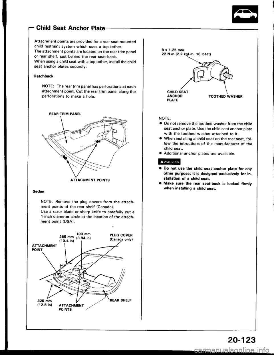
Attachment points are provided for a rear seat mountedchild restraint system which uses a top tether,
The attachment points are located on the rear trim panel
or rear shelf, just behind the rear seat-back.
When using a child seat with a top tether, installthe childseat anchor plates securely.
Hatchback
NOTE: The rear trim panel has perJorations at each
attachment point. Cut the rear trim panel along theperforations to make a hole,
Sedan
NOTE: Remove the plug covers from the attach-ment points of the rear shelf (Canada).
Use a razor blade or sharp knife to carefully cut a1 inch diameter circle at the location of the attach-ment point (USAI.
265 mm(10.4 inl
IOO mm13.94 inl
BEAR TRIM PANEL
ATTACHMENT POINTS
TOOTHED WASHER
NOTE:
a Do not remove the toothed washer from the child
seat anchor plate. Use the child seat anchor plate
with the toothed washer attached to it.a When installing a child seat on the rear seat, fol-low the intructions of the manufacturer of thechild seat,a Additional anchor plates are available.
a Do not use the child seat anchor plate for any
other puipos€; it is dosigned exclusively tor in-
stallation of a child seat.
a Mako sure tho roar seat-back is locked firmlvwh€n installing a child soat.
REAR SHELF
20-123
Page 1004 of 1413
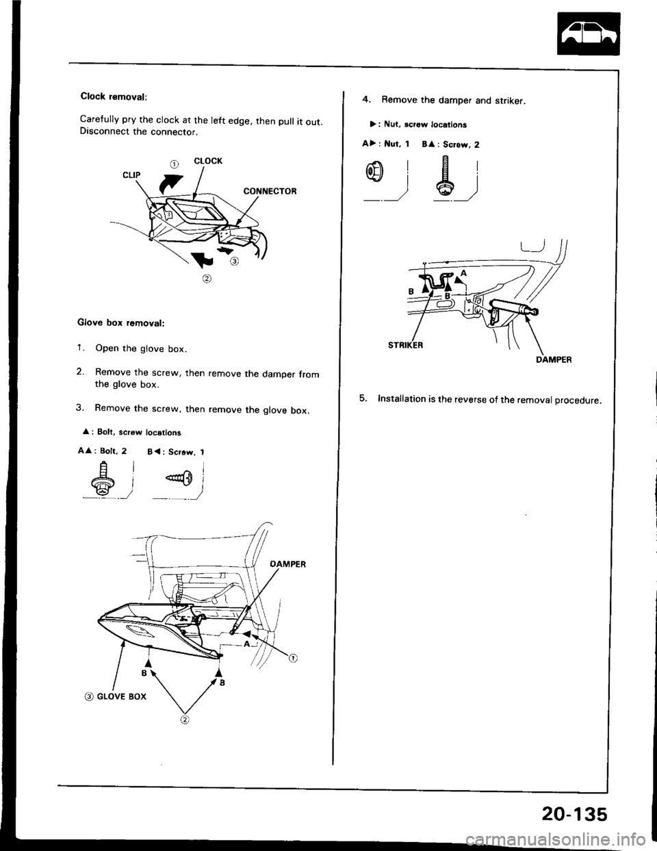
Clock rsmoval:
Caretully pry the clock at the left edge. then pull it out.Disconnect the connector.
CONNECTOR
tl
@
Glove box removal:
'1. Open the glove box.
2. Remove the screw, then remove the damper fromthe glove box.
3. Remove the screw, then remove the glove box.
: Bolt, scr6w locstions
A
: Bolt,
A
6
l^l
)P)
2 B<: Scrow, 1
CLOCK
4. Remove the damper and striker.
>: Nut, icrgw locations
A> : l{ut, 1 B
: Scrow, 2
,-.\'Flot]}lEl\+!lal
_ __,/ *' ,/
5. Installation is the reverse o{ the removal orocedure.
DAMPER
20-135
Page 1006 of 1413
Replacement
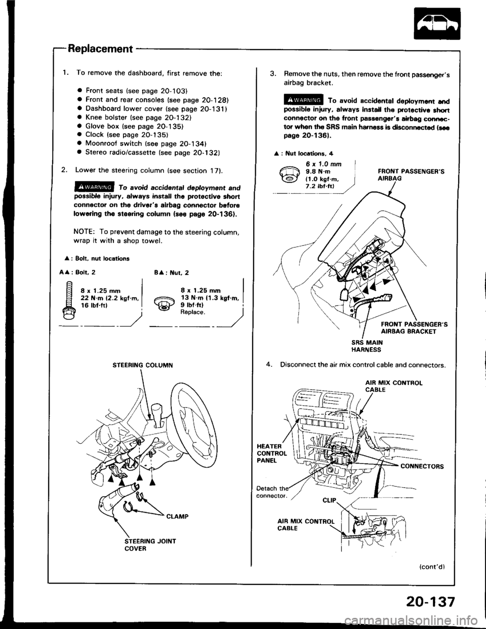
To remove the dashboard, first remove the:
a Front seats (see page 2O-103)
a Front and rear consoles (see page 20-128)a Dashboard lower cover (see page 2O-131)a Knee bolster (see page 2O-132)a Glove box lsee page 2O-135). Clock (see page 20-135)
a Moonroot switch (see page 20-1341a Stereo radio/cassette {see page 20-132)
Lower the steering column (see section 17).
@@ ro avoid accidentat dedoyment andpossiblo in ury, always install the prot€ctive short
connector on tho drivsr's airbag connector bgtor€
lowering tho stooring column (so€ page 20-1361.
NOTE: To prevent damage to the steering column,
wrap it with a shoD towel.
: 8olt, nul locations
A
: Bolt, 28 : ut, 2
8 x 1.25 mm22 N-m 12.2 ksl.m,16 lbt.frl
8 x 1.25 mm
gill$"'l
STEERING COLUMN
3. Remove the nuts, then remove the front passsnger,s
airbag bracket,
@ To avoid accidantar daploym.nr ",'dpossibls iniury, always install th€ protoctiv. 3hqtconnoctor on tho ,ront passongor'a airbag conncc-tor whon tha SRS main ha.na$ is disconncctod llcrpago 20-136).
: Nut locatlons, 4
FRONT PASSENGER'S
FRONT PASSENGER'SAIRBAG BRACKET
4.
SRS MAINHARNESS
Disconnect the air mix controlcable and connectors.
AIR MIX CONTROLCAELE
CONNECTORS
(cont'dl
20-137
Page 1013 of 1413
Hood
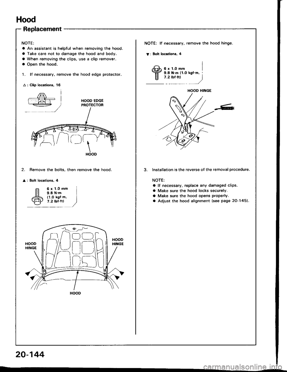
Replacement
NOTE:
a An assistant is helplul when removing the hood.
a Take care not to damage the hood and body.
a When removing the clips, use a clip remover.
a Open the hood.
1. It necessary, remove the hood edge protector.
: Clip loc.tions, 16
NOTE: It necessary, remove the hood hinge.
V : Boh locationa, 4
I3;;,iH"-,,., I
j .rtor"t
- )
HOOD EDGEPROTECTOR
\HOOD
2. Remove the bolts. then remove the hood.
: Bolt localions, 4
lnstallStion is the reverse of the removal procedure.
NOTE:
a lf necessary, replace any damaged clips.
a Make su.e the hood locks securely.
a Make sure the hood opens properly.
a Adjust the hood alignment (see page 20-1451.
6x1.0mm9.8 N'm{l.O kgl m,7.2 lbl.fr)
HOOD HINGE
n
r)
HOOD
20-144
Page 1016 of 1413
8.
o.
7.
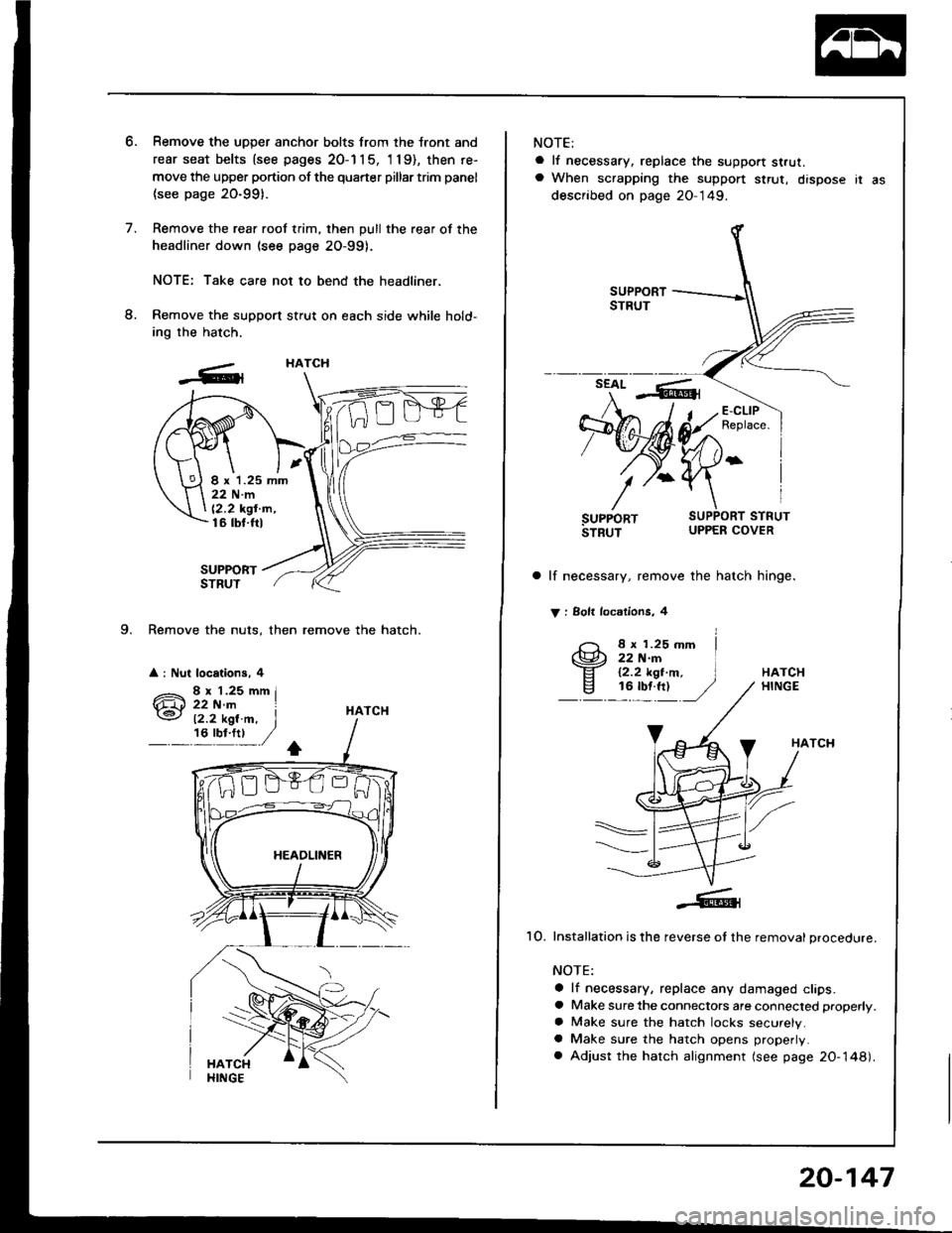
9. Remove the nuts, then remove the hatch.
a : Nut locations, 4
Remove the uDDer anchor bolts from the tront and
rear seat belts {see pages 20-1 1 5, 'l 19), then re-
move the upper portion of the quarter pillar trim panel
(see page 20-991.
Remove the rear roof trim, then pull the rear of the
headliner down (see page 2O-99).
NOTE: Take care not to bend the headliner,
Remove the support stfut on each side while hold-
ing the hatch.
SUPPORTSTRUT
HATCH
HATCH
I x 1.25 mm22Nm
12,2 kgt'm,16 tbt.ftl
12.2 kgl.m, I,6'y!:t ,/
NOTE:
a lf necessary, replace the support strut.a When scrapping the suppon $rut, dispose ir as
described on page 20-149.
a lf necessary, remove the hatch hinge.
V : Solt locdlions, 4
8 x 1.25 mm22 N.rn12.2 kgt.m,16 tbf.ft)HATCHHINGE
HATCH
1O. Installation is the reverse ot the removal procedure.
NOTE:
a lf necessary, replace any damaged clips.a Make sure the connectors are connected properly.
a Make sure the hatch locks securely.a Make sure the hatch opens properly.
a Adjust the hatch alignment (see page 20-148).
20-147
Page 1019 of 1413
Trunk Lid
Replacement (cont'dl
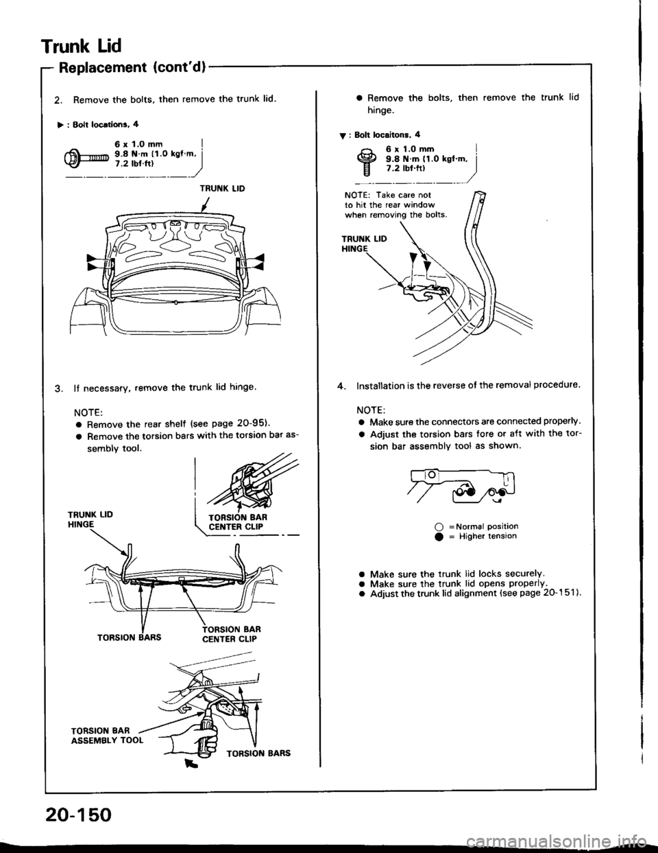
2. Remove the bolts. then
> : Bolt loc.rlons. 4
remove the trunk lid.
TRUNK LIDHINGE
lf necessary. remove the trunk lid hinge
NOTE:
a Remove the rear shelf {see page 20-95).
a Remove the torsion bars with the torsion bar as-
sembly tool.
TORSION 8ABASSEMBLY TOOL
20-150
a Remove the bolts,
hinge.
V : Bolt locaitons, 4
then remove the trunk lid
NOTE: Take care notto hit the rear windowwhen removing the bolts.
TRUNK LID
4. lnstallation is the reverse ot the removal procedure.
NOTE:
a Make sure the connectors are connected properly.
a Adjust the torsion bars tore or aft with the tor-
sion bar assemblv tool as shown.
O =Normal PositionO = Higher tension
Make sure the trunk lid locks securely.Make sure the trunk lid opens properly.
Adjust the trunk lid alignment (see page 20-151).
aaO
Page 1023 of 1413
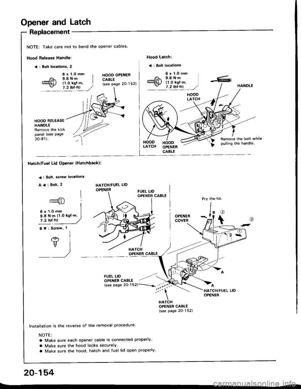
Opener and Latch
Replacement
NOTE: Take care not to bend the opener cables.
Hood Relsase Handle:
< i Bolt locations, 2
Hood Latch:
< : Bolt locations
6 x 1.0 mm9.8Nm(1.0 kgl m,7.2 tbl.lrl
HOOD OPENERCABLE(see page 20'152)
6 x 'l.O mm9.8Nm11.0 kgl m,7 .2 tbt ftl,/HANDLE
HOODLATCH
HOOD RELEASEHANOLERemove the kickpanel (see page
20-91).HOODLATCHHOODOPENERCABLE
Remove the bolt whilepulling the handle.
I
Hatch/Fuel Lid Opener lHatchback):
< : Bolt, sclow locations
A
6' I
vl
/
HATCHiFUEL LID
OPENER
6 x 1.0 mm
9.8 N m 11.0 kgl'm,
7.2 tbl.fr)
FUEL LIDOPENER CAELE
lnstallation is the reverse of the removal procedure'
NOTE:
a Make sure each opener cable is connected properly
a Make sure the hood locks securely
a Make sure the hood, hatch and fuel lid open properly.
the
J'o
t
OPENERCOVER
HATCHOPENER CABLE(see page 20-152)
@
t-
20-154
Page 1024 of 1413
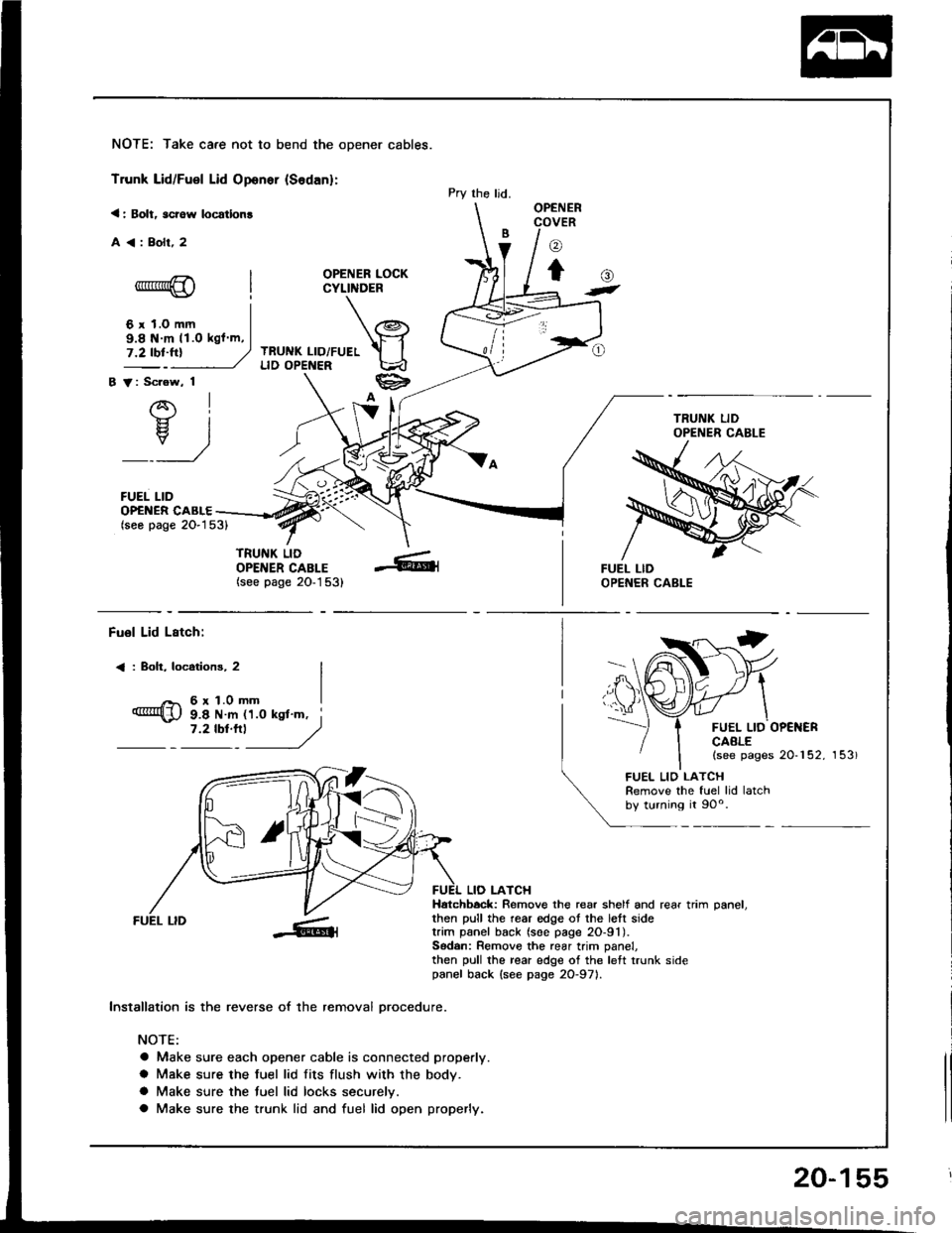
NOTE: Take care not to bend the opener cables.
Trunk Lid/Fuel Lid Oponer {Sodan}:
< : Bolt, scrow locatlon!
A<:Bolr,2
OPENER LOCKCYLINDER
TRUNK LID/FUELLID OPENER
B V: Scrow, 1
AI-}{- IH. I
_:_)
FUEL LID
Pry the ljd.OPENERCOVER
o
to-*rr*@
6 r 1.0 mm
()t
OP€NER CABLE(seo page 2O-153)
TRUNK LIDOPENER CABLE(see page 20-1 53)
9.8 N m 11.O kgl m,
Fuol Lid Lstch:
< : Boh, locotions, 2
6r1.0mm
FUEL LID OP€NERCAALE(see pages 20-152, 153)
9.8 N m 11.0 ksl'm, i7 '2 tbt'''l
------,//
FUEL LID
lnstallation is the reverse of the removal orocedure.
NOTE:
a Make sure each opener cable is connected properly.
a Make sure the fuel lid fits flush with the body.
a Make sure the tuel lid locks securelv.
a Make sure the trunk lid and fuel lid open properly.
LIO LATCHHatchbock: Remove the rear shelf and rear trim oanel.then pull the rear edge ot the lett sidetrim panel back (soe page 2O-91).Sodan: Remove the rear trim panel,then pull the rear edge of the left trunk sidepanel back {see page 2O-971.
FUEL LIO LATCHRemove the fuel lid latchby turning it 90o.
20-155