lock HONDA INTEGRA 1994 4.G Workshop Manual
[x] Cancel search | Manufacturer: HONDA, Model Year: 1994, Model line: INTEGRA, Model: HONDA INTEGRA 1994 4.GPages: 1413, PDF Size: 37.94 MB
Page 672 of 1413
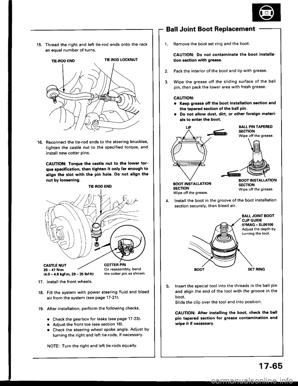
15.Thread the right and lefi tie-rod ends onto the rack
an eoual number of turns.
TIE-ROO ENDTIE.ROD LOCKNUT
R€connect the tie-rod ends to the steering knuckles,
tighten the castle nut to the specified torque, and
install new cotter pins.
CAUTION: Iorquo tho castle nut to tho lower tor-
que lpocification, thsn tighton it only far cnough to
align thc slot with tho pin hole. Do not align tho
nut by loosoning.
CASILE NUT39 - 47 N.m14.0 - a.8 kgf.m. 29 - 35 lbf ftl
17. lnstallthe front wheels.
18. Fill the system with pgwer steering fluid and bleed
air from the system (see page 17-21).
19. After installation. perform the following checks.
. Check the gearbox Jor leaks (see page 17-231
. Adjust the front toe (see section 18).
o Check the steering wheel spoke angle. Adjust by
turning the right and left tie-rods, if necessary.
Ball Joint Boot Replacement
Remove the boot set ring and the boot.
CAUTION: Do not contaminate ihe boot in3talls-
tion section with gr€aso.
Pack the interior of the boot and lip with grease.
Wipe the grease off the sliding surface of the ball
pin, then pack the lower area with fresh grease.
CAUTION:
. Ke€p g;eass off the boot in3tallation section and
tho laperad section of the ball pin.
. Do not altow dust, di.t, or other toreign mat6ti-
als to enter tho boot,
LIPBALL PIN TAPEREDSECTIONWipe off the grease.
BOOT INSTALLATIONSECTIONwiDe off the grease.
BOOT INSTALLATIONSECTIONWipe off the grease.
COTTER PINOn reassembly, bendthe cotter pin as shown.
Install the boot in the groove ot the boot installation
section securely, then bleed air.
SALL JOINT BOOTCLIP GUIDE07MAG - SL(x)l00Adiust the depth byturning the tool.
SET RING
Insert the special tool into the threads in the ball pin
and align the end of the tool with the groove in the
boot.
Slide the clip over the tool and into position
CAUTION: After installing the boot, check th. b.ll
pin taperod section tor grease contamiration and
wipe it if nocossary.
NE.ROD END
Turn the right and left tie-rods equally.
17-65
Page 914 of 1413
R6ar Door:
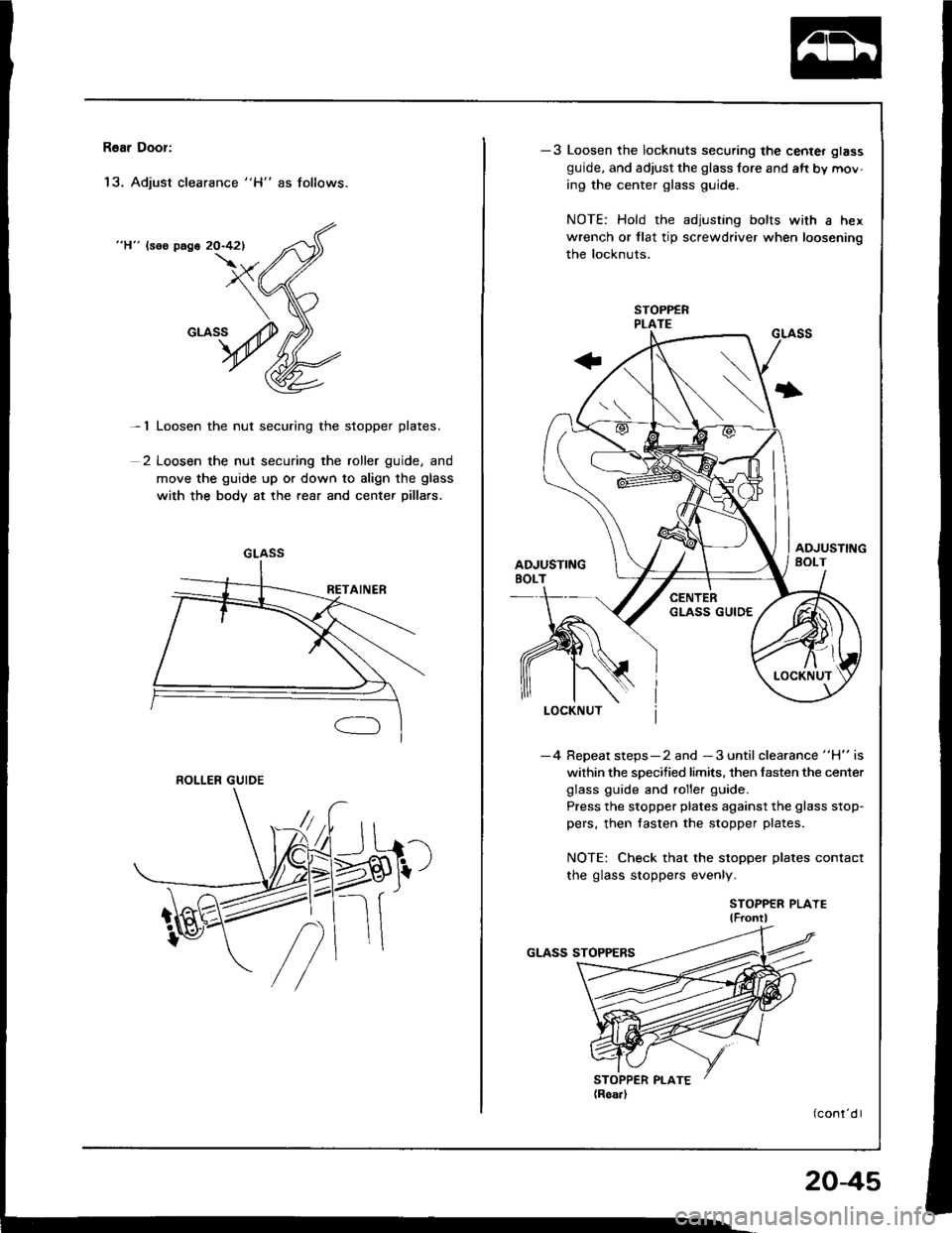
'13. Adjust clearance "H" as follows.
"H" lsos page 20-421
- 1 Loosen the nut securing the stopper plates.
2 Loosen the nut securing the roller guide, and
move the guide up or down to align the glass
with the body at the rear and center pillars.
GLASS
ROLLER GUIDE
-3 Loosen the locknuts securing the center glass
guide, and adjust the glass fore and aft by mov-
ing the center glass guide.
NOTE: Hold the adjusting bolts with a hex
wrench or tlat tip screwdriver when loosening
the locknuts.
I
-4 Repeat steps-2 and -3 until clearance "H" is
within the specified limits. then fasten the center
glass guide and roller guide.
Press the stopper plates against the glass stop-
pers, then fasten the stopper plates.
NOTE: Check that the stopper plates contact
the glass stoppers evenly.
STOPPER PLAYElF ontl
204s
Page 915 of 1413
Doors
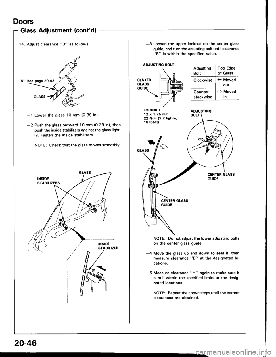
14. Adjust clearance "8" as follows.
"8" (see page 20-421
Lower the glass 1O mm {0.39 in).
Push the glass outward 1O mm (O.39 inl. then
push the inside stabilizers against the glsss light-
ly. Fasten the inside stabilizers.
NOTE: Check that the glass moves smoothly.
Glass Adjustment (cont'dl
-l
-2
20-46
-3 Loosen the upper locknut on the center glass
guide, and turn the adiusting bolt until cleatance"B" is within the soecified value.
ADJUSTING EOLT
LOCKNUT12 x 1.25 mm22 N.m 12.2 kgf.m,16 tbt.ft)
*
GLASS
NOTE: Do not adjust the lower adjusting bolts
on the center glass guide.
-4 Move the glass up and down to seat it, then
measure clearance "8" at the designated lo-
cattons.
- 5 Measure clea.ance "H" again to make sure it
is still wilhin the specified limits at the desig-
nated locations.
NOTE: Repeat the above steps until the correct
clearances afe obtained.
Page 952 of 1413
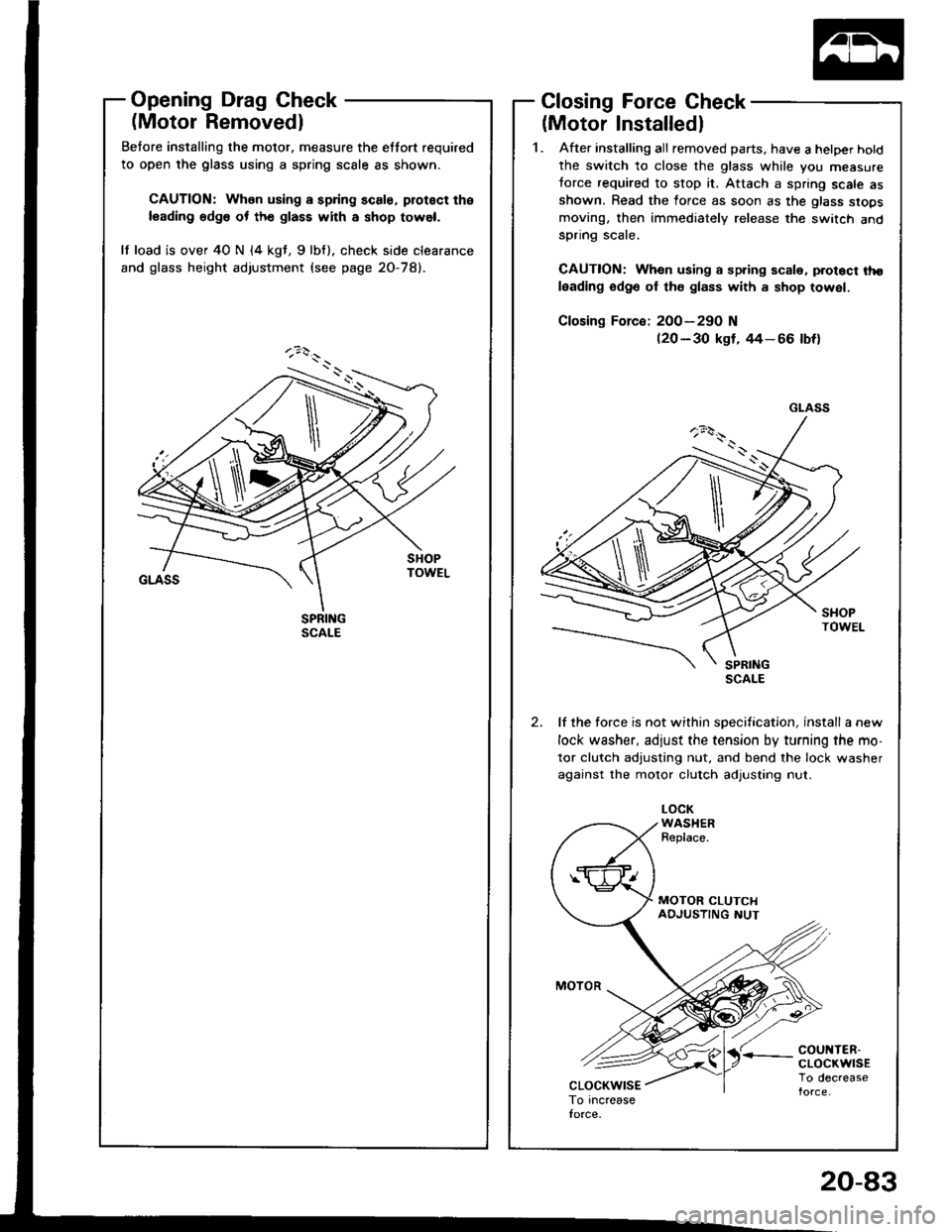
Opening Drag Check
(Motor Removedl
Betore installing the motor, measure the etfort required
to open the glass using a spring scale as shown.
CAUTION: When using a spring scale, protoct the
leading edg6 ot th€ glass with a shop towel.
lf load is over 40 N (4 kgt, 9lbf). check side clearance
and glass height adjustment (see page 2O-78).
Closing Force Check
(Motor Installedl
1. After installing all removed parts, have a hetper hotd
the switch to close the glass while you measure
torce required to stop it. Attach a spring scale asshown. Read the force as soon as the glass siops
moving, then immediately release the switch andspnng scare.
CAUTION: When using a spring scale, protoct tho
leading odge ol th€ glass with a shop towel.
200-290 N(20 - 30 kgf, rt4- 66 lbf)
lf the force is not within specification, install a new
lock washer, adjust the tension by turning the mo-
tor clutch adjusting nut, and bend the lock washer
against the motor clutch adjusting nut.
LOCKWASHERReplace.
'r coul{TER-cLocKwrsETo decrease
GLASS
\
20-83
Page 959 of 1413
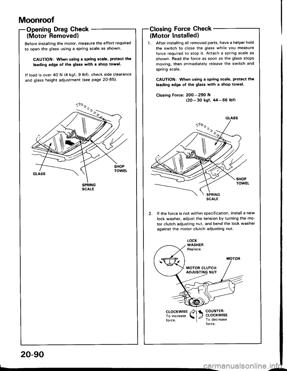
Moonroof
Opening Drag Check
(Motor Removed)
Before installing the motor. measure the effort required
to open the glass using a spring scale as shown
CAUTION: Whon using a spring scalo. protoct the
l€ading odge ol the glass with a shop tow€I.
lf load is over 40 N (4 kgl, 9lbt), check side clearance
and glass height adiustment (see page 20-85)'
Closing Force Check
lMotor Installed)
1. After installing all removed parts, have a helper hold
the switch to close the glass while you measure
force required to stop it. Attach a spring scale as
shown. Read the torce as soon as the glass stops
moving, then immediately release the switch and
spring scale.
CAUTION: When using a sp ng scala. protect th€
leading odge ol the glass with a shop towel'
Closing Force: 200-290 N
120-30 ksf. 44-66 lbf)
lf the lorce is not within specification, install a new
lock washer. adjust the tension by turnang the mo-
tor clutch adjusting nut, and bend the lock washe.
against the motor clutch adjusting nut.
GLASS
\
clocKwlsE /i 1 coutren-
To increase l, ctocKwlsE
torce, I Io decreaseforce
L.
20-90
--
Page 963 of 1413
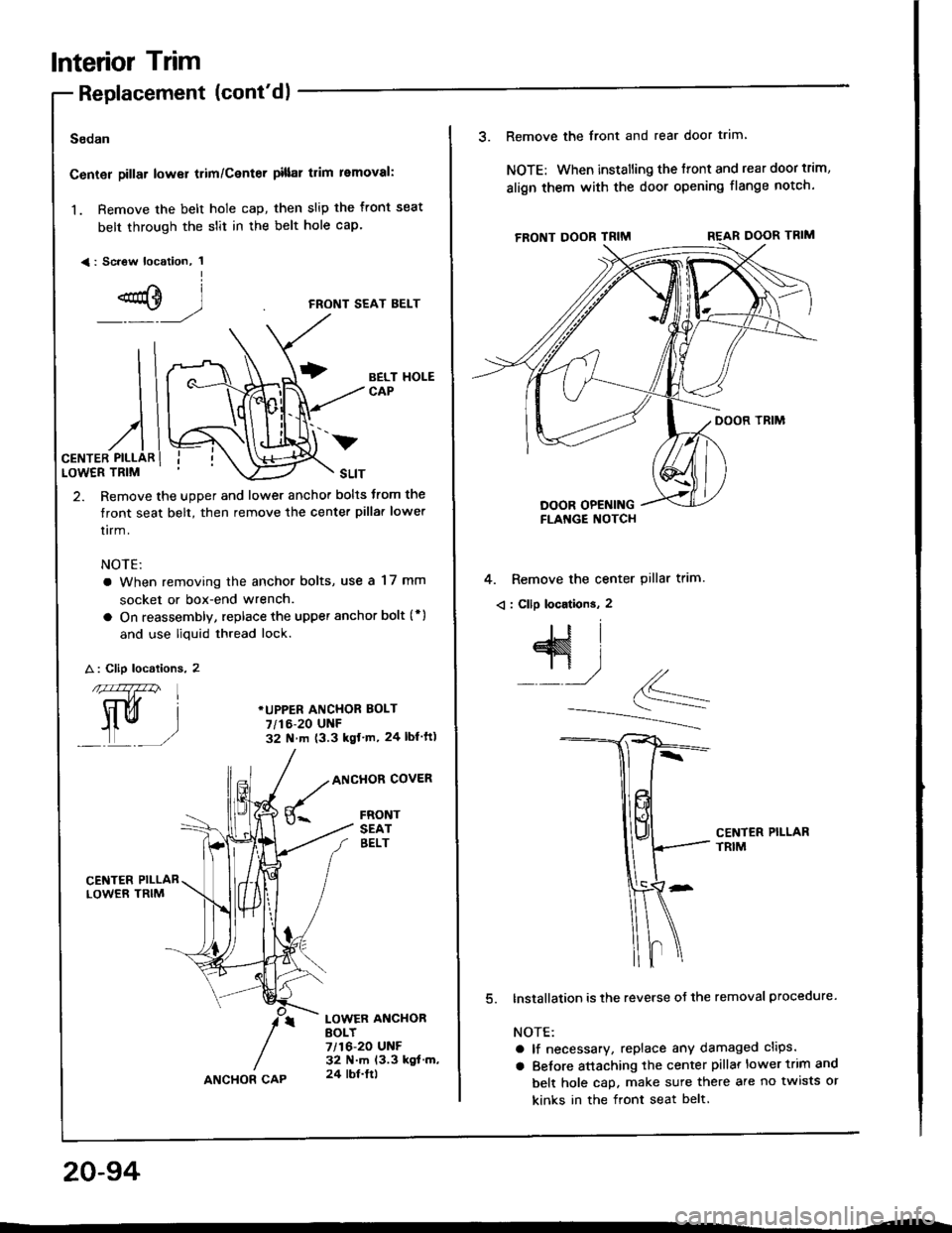
lnterior Trim
Replacement lcont'dl
Sodan
Center pillar lower trim/Center pillal trim removal:
1. Remove the belt hole cap, then slip the front seat
belt through the slit in the belt hole cap.
<: Sc.ew location, 1I
e)
)
2. Remove the upper and lower anchor bolts trom the
tront seat belt, then remove the center pilla. lower
tirm.
NOTE:
a When removing the anchor bolts, use a 17 mm
socket or box-end wrench.
a On reassembly, replace the upper anchor bolt (* )
and use liquid thread lock.
CENTER PILLARLOWER TRIM
FRONT SEAT BELT
BELT HOLECAP
*UPPER ANCHOR EOLT
7/t6-20 UNF32 N m (3.3 kgf'm, 24 lbl ft)
A : Clip localions. 2
nfa147zzn
trui
L_,)
ANCHOR COVER
FRONTSEATEELT
CENTER PILLARLOWER TRIM
LOWER ANCHORBOLY7/16-20 UNF32 N.m 13.3 kgt.m,24 lbt.ltlANCHOR CAP
20-94
v
3. Remove the front and rear door trim
NOTE: When installing the ffont and rear door trim,
align them with the door opening flange notch.
4. Remove the center pillar trim.
< : Cllp locations. 2
CENTER PILLARTRIM
lnstallation is the reverse oJ the removal procedure.
NOTE:
a lf necessary, replace any damaged clips.
a Belore attaching the center pillar lower trim and
belt hole cap. make sure there are no twists or
kinks in the front seat belt.
Page 964 of 1413
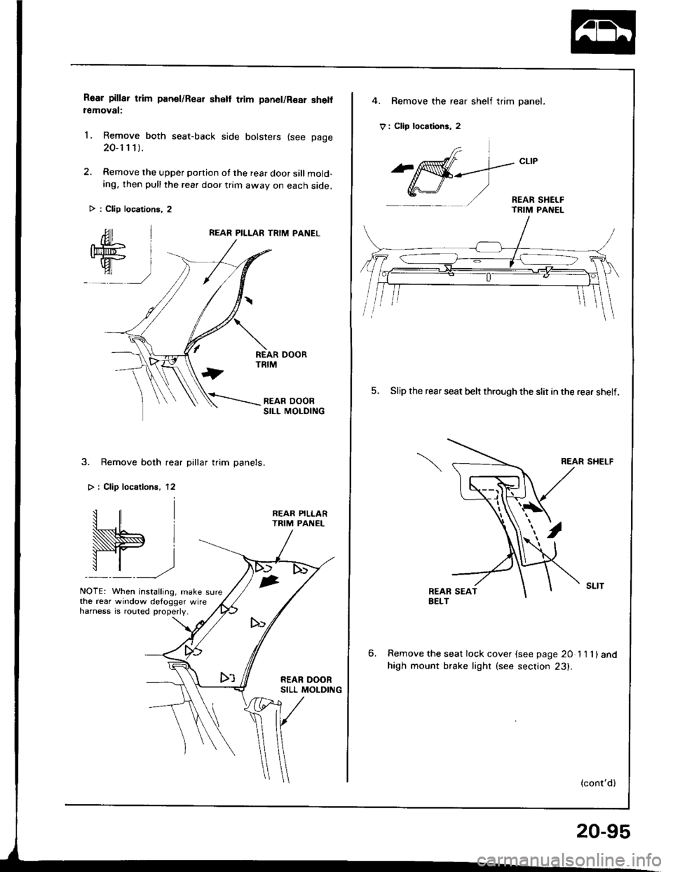
Roar pillar tlim panel/Rear shell trim panel/Rsar she removal:
1. Remove both seat-back side bolsters {see page
20-1 1 1).
2. Remove the upper portion of the rear door sill mold-ing, then pull the rear door trim awav on each side.
REAR PILLAR TRIM PANEL
3. Remove both rear pillar trim panels.
> i Clip localionr, 12
W.,
NOTE: When installing, make sure
REAR PILLARTRIM PANEL
the rear window defogger wireharness is .outed properly.
> : Clip locations, 2
4. Bemove the rear shelf trim panel.
V : Clip locrtions, 2
frl
^affi-_--.]-"t't
Y,r\-J/ '/ - REAR sHEr-F- TRIM PANEL
5. Slip the rear seat belr through the slit in the rear shelf.
REAR SHELF
6.Remove the seat lock cover {see page 20 11 1)and
high mount brake lighr (see section 23).
(cont'd)
20-95
Page 967 of 1413
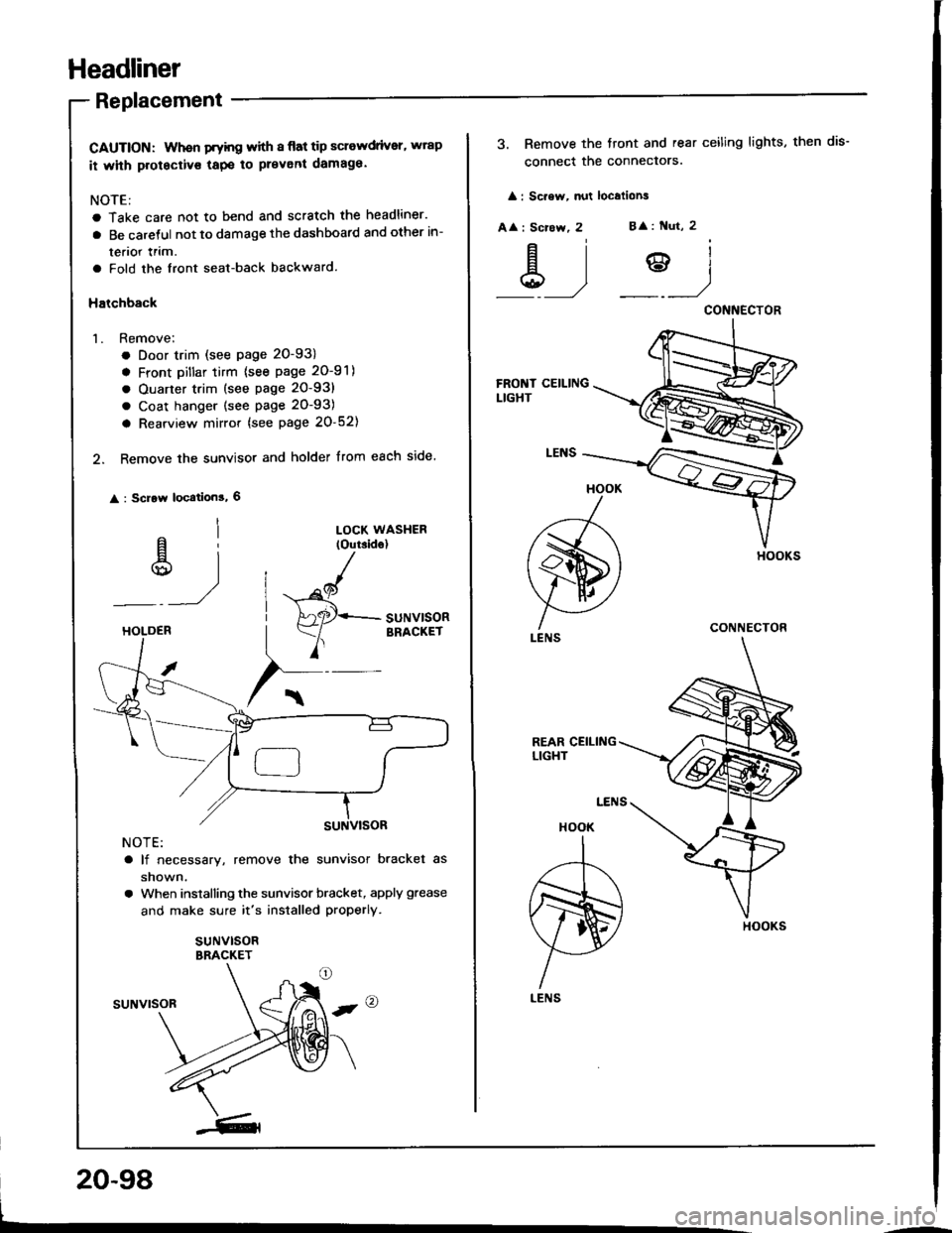
Headliner
Replacement
CAUTION: Whon Fyhg with I flat tip sclewdrivsr, wrap
it whh protectivs tapo to prevent damaga.
NOTE:
a Take care not to bend and scratch the headliner.
a Be caretul not to damage the dashboard and other in-
terior lrim.
a Fold the front seat-back backward.
Halchback
1. Remove;
. Door trim (see page 20-93)
a Front Dillar tirm {see page 20-91)
a Ouarter trim (see page 20-93)
a Coat hanger (see page 20-93)
a Rearview mirror {see page 20-52)
2. Remove the sunvisor and holder from each side.
: Scrow location!, 6
al
u)
LOCK WASHER(Outside)
"^/
HAaqr+- SUNV|SOR
Y
BRACKETHOLDEB
NOTE:
a lf necessary, remove the sunvisor bracket as
shown.
a When installing the sunvisor bracket, apply grease
and make sure it's installed properly.
suNvlsoRBRACKET
suNvrsoR
20-98
3. Remove the tront and rear ceiling lights, then dis-
connect the conneclors.
: Sc.ew, nut localions
A
: Scrcw, 2B
: Nut, 2
&)?)
HOOK
A
ffi)
LENS
HOOK
I
,r--T-\
m)
H
LENS
CONNECTOR
CONNECTOR
HOOKS
Page 969 of 1413
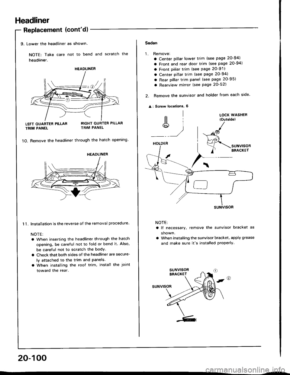
Headliner
9, Lower the headliner as shown.
NOTE: Take care not to bend and scratch the
headliner.
Replacement {cont'd)
LEFT OUARTER PILLAR
TRIM PANEL
11.
RIGHT OURTER PILLARTRIM PANEL
1O. Bemove the headliner through the hatch opening'
Installation is the reverse of the removal procedure.
NOTE:
a When inserting the headliner through the hatch
opening, be careful not to fold or bend it. Also,
be careful not to scratch the bodY.
a Check that both sides of the headliner are secure-
ly attached to the trim and Panels.
a When installing the roof trim, install the Joint
toward the rear.
20-100
HEADLINER
HEADLINER
Sodan
'1.Remove:
a Center Dillar lower trim (see page 20-94)
a Front and rear door trim lsee page 20-94)
a Front pillar trim (see page 2O-9 .
a Center pillar trim (see page 20-94)
a Rear pillar trim panel (see page 20 95)
a Rearview mirror (see Page 20-521
Remove the sunvisor and holder from each side
: Screw locationS, 6
2.
^l
s,1
LOCK WASHER
loutsidel
HOLDER
/
$-.unu,"o"
/' BRACKET
NOTE:
a lf necessary, remove the sunvisor bracket as
shown.
a When installing the sunvisor bracket, apply grease
and make sure it's installed properly.
,@
suNvrsoR
Page 972 of 1413
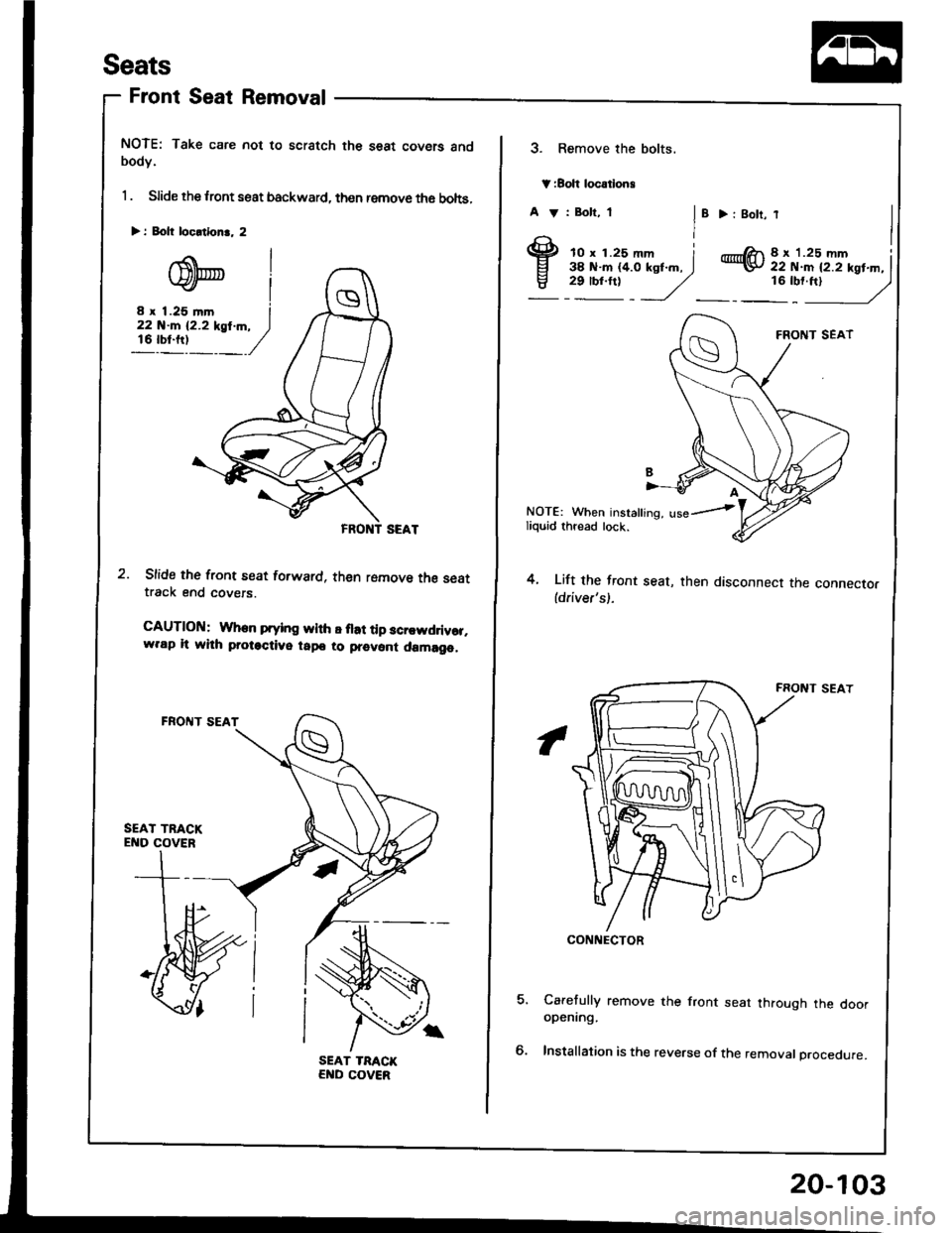
Seats
Front Seat Removal
NOTE: Take care not to scratch the seat covers andbodY.
1 . Slide the lront seat backward, then remove th6 bohs,
Slide the front seat forward, then romove the seattrack end covers.
CAUTlOltl: When prying wlth E flat tip scr.wddvor,w.ap lt whh protactive tapo to prevont damago,
> i Eolt locltlon.. 2
3. Remove the bolts.
V:Boh locatlong
A V : Bolt, 1
I'
> : 8olt,
@8 x '1.25 mm Iii i.:iiil..i'xst.^. I16:t'ftt
- /)
4.
NOTE: When insralling, use--iliquid thread lock.
Lift the front seat, then disconnect the connector(driver's).
Carefully remove the front seat through the dooropening.
Installation is the reverse of the removal procedure.
CONNECTOR
20-103