lock HONDA INTEGRA 1994 4.G Workshop Manual
[x] Cancel search | Manufacturer: HONDA, Model Year: 1994, Model line: INTEGRA, Model: HONDA INTEGRA 1994 4.GPages: 1413, PDF Size: 37.94 MB
Page 634 of 1413
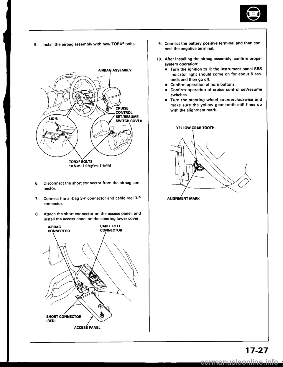
5. Install the airbag assembly with new TORXo bolts.
TORXO BOLTS10 N.m {1.0 kgf'm.7 lbf ftl
Disconnect the short connector trom the airbag con-
nector.
Connect the airbag 3-P connector and cable reel 3-P
connector.
Attach the short connector on the access panel. and
install the access panel on the steering lower cover.
CABLE REEI-CONNECTOR
7.
YELLOW GEAR TOOTH
ALIGNMENT MARK
10.
Connect the battery positive terminal and th€n con-
nect the nsgative terminal.
After installing the sirbag assembly, confirm proper
system opera(on:
. Turn the ignition to ll: the instrum€nt pan6l SRS
indicator light should come on for about 6 sec-
onds and then go off,
. Confirm operation of horn buttons.
. Confirm oDeration of cruise control sevresume
switches.
a Turn the steering wheel countetclockwise and
make su.e the yellow gear tooth still lines up
with the alignment mark.
17-27
Page 637 of 1413
Steering Column
lnspection
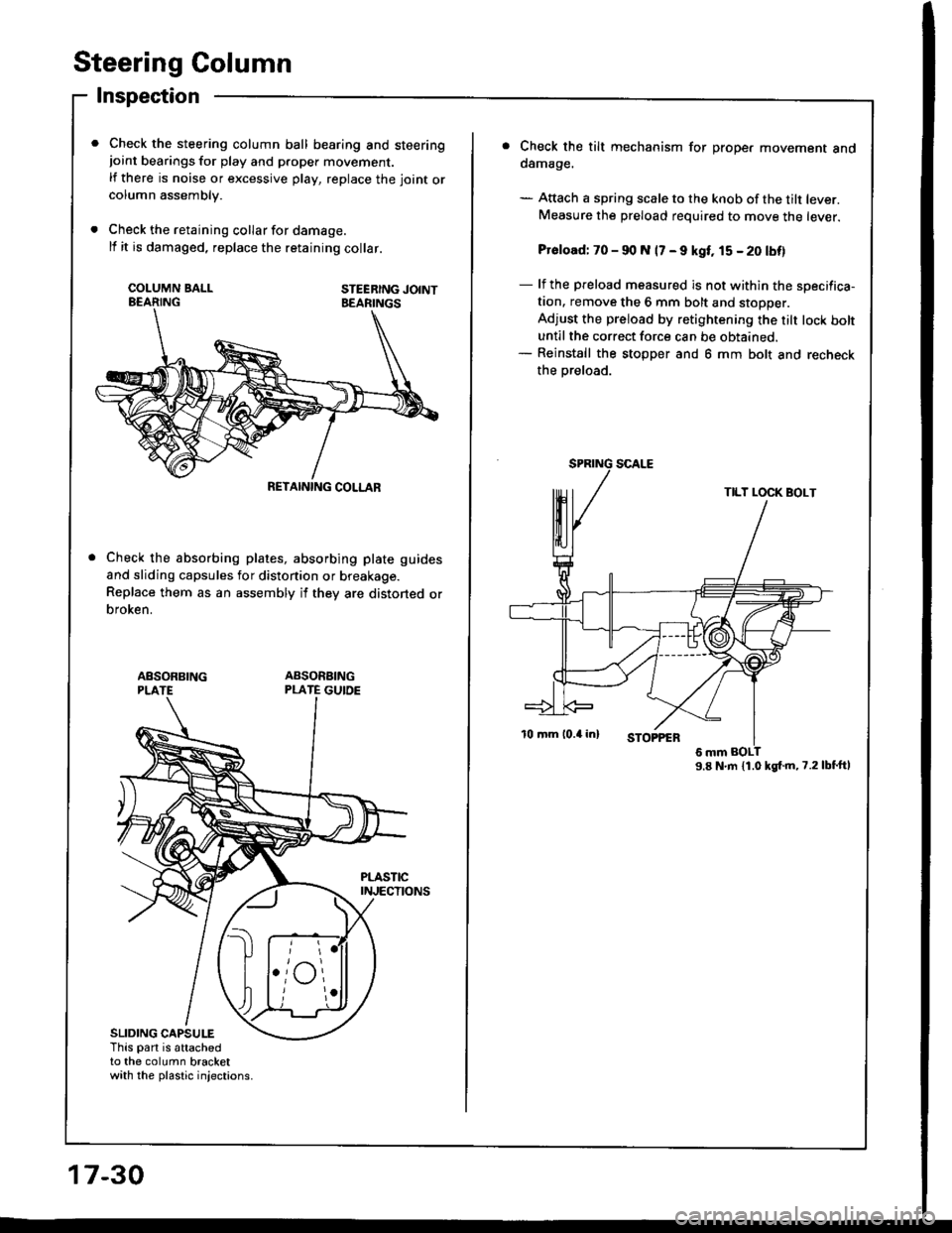
Check the steering column ball bearing and steeringjoint bearings for play and proper movement.
lf there is noise or excessive play, replace the joint orcolumn assembly.
Check the retaining collar for damage.
lf it is damaged, replace the retaining collar.
COI-UMN BALLEEARINGSTEERING JOINTBEARINGS
RETAINING COLLAR
Check the absorbing plates, absorbing plate guides
and sliding capsules for distonion or breakage.
Replace them as an assembly if they are distoned orbroken.
ABSONBING
SLIDING CAPSULEThis part is attachedto the column bracketwith the plastic injections.
17-30
Check the tilt mechanism for proper movement andoamage.
- Attach a spring scale to the knob of the tilt lever.Measure the preload required to move the lever.
Pr6load: 70 - 90 N 17 - 9 kgt, 15 - 20 tbf)
- lf the preload measured is not within the sDecifica-tion. remove the 6 mm bolt and stoDDer.
Adjust the preload by retightening the rilt tock boltuntil the correct force can be obtained.- Reinstall the stopper and 6 mm bolt and recheck
the Dreload.
9.8 N'm {1.0 kgt.m,7.2lbt'ftl
TILT LOCK BOLT
Page 651 of 1413
Power Steering Pump
lnstallation
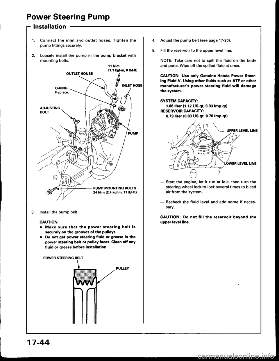
1.Connect the inlet and outlet hoses. Tighten the
pump fiftings securely.
Loosely install the pump in the pump bracket with
mounting bolts.
11N.m11.r kgf.m, 8lbf.ftlOUTIIT HOUSE
INI.TT HOSEO-RINGReplaco.
ADJUSTINGBOLT
PUMP MOUNTING BOLTS2,r N.m {2.4 kgl.m. 17 lbf'ft}
Install the DumD belt.
CAUTION:
. Make surs that thg powor gtooring bslt i!
securgly on the grooyos of ths pulloy!.
. Do not get powor stggring fluid o. groaso in thg
power steering bclt or pulley trc6. Cloan oft 8ny
tluid or groa36 belore installation.
POWER STEERING BELT
PULI..EY
5.
Adjust the pump belt (see page 17-201.
Fill the reservoir to the uoDer level line.
NOTE; Take care not to spill the fluid on the body
and parts. Wipe off the spilled fluid at once.
GAUTION: Uro only Ganuino Honda Powor Stsor.
ing Fluid-V. Using othor tlui& 3uch a3 ATF or oiher
manutacturor's powor steering tluid will drm89e
the rystgm.
SYSTEM CAPACITY:
1.06litor (1.12 US.qt, 0.93 lmp.qt)
RESERVOIR CAPACIW:
0.79 litor (0.1|:| US.qt, 0.?0 lmp.qtl
UP?ER I.fVEL LINE
IEVEI LINE
- Start the engine, let it run at idle, then turn the
steering wheel lock-to-lock severaltimes to bleed
air from the system.
- Recheck the fluid level and add some if neces-
s8ry.
CAUTIONT Do not fill tha .63ervoir boyond th6
upp€r lcvol lino.
17 -44
Page 652 of 1413
Steering Gearbox
Removal
NOTE: Using solvent and a brush, wash any oil and dirt
off the valve body unit, its lines, and the end if the gear-
box. Blow dry with compressed air.
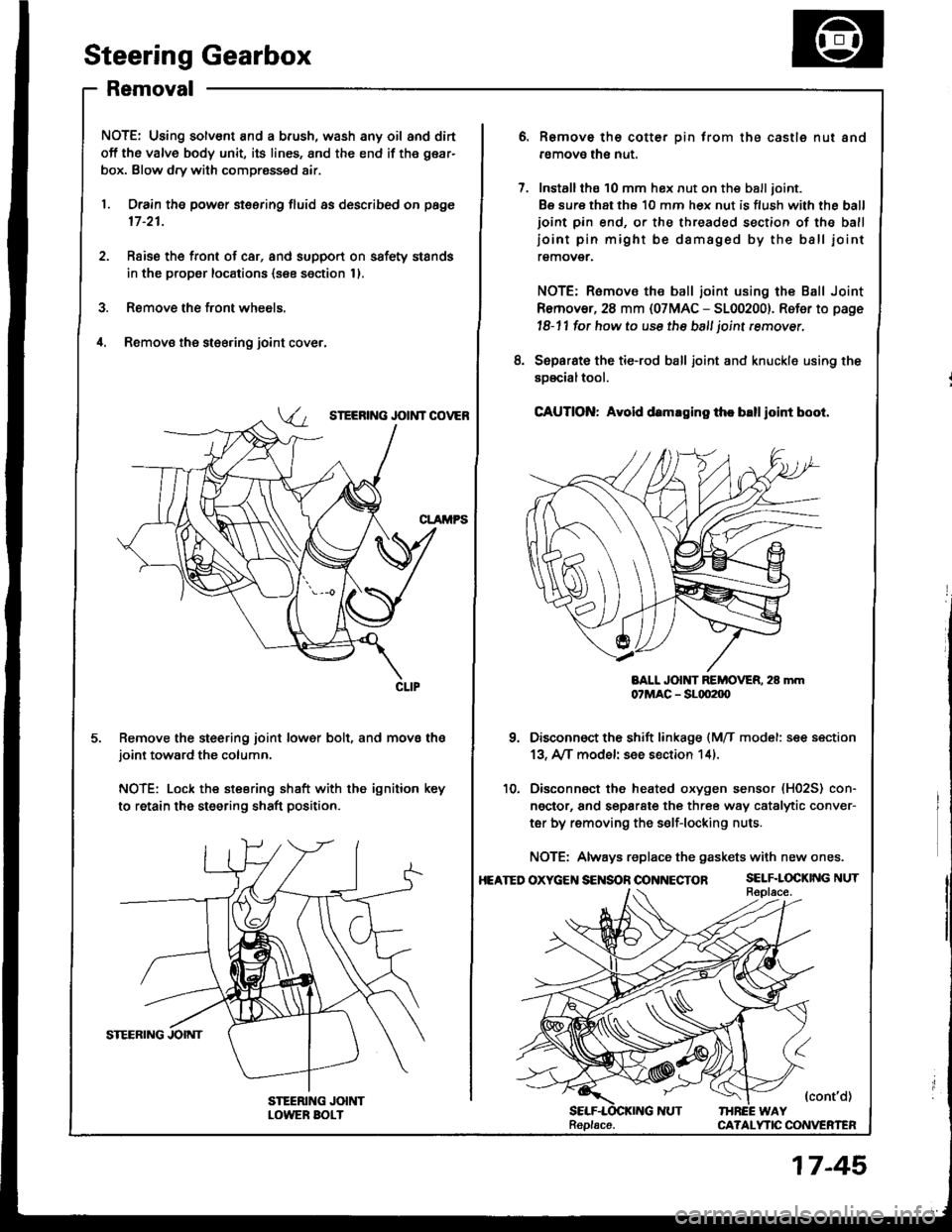
1. Drain the power steering fluid as described on page
17 -21.
2. Rsise the front of car, and support on safety stands
in the propsr locations (see section 1).
3. Remove the front wheels.
il. Removs the st€ering joint cove.,
SIEERING JOIi{T COVEB
Remove the steering joint lower bolt, and move thejoint toward the column.
NOTE: Lock the steering shaft with the ignition key
to retain the steering shaft position.
Remove the cotter pin trom the castle nut and
removo the nut.
Installthe 10 mm hex nut on the balljoint.
Be sure that ths 10 mm hex nut is flush with the ball
ioint pin end, or the threaded section of the ball
ioint pin might be damaged by the ball iointremover.
NOTE: Remove the ball joint using the Ball Joint
Remover, 28 mm {07MAC - 5100200}. Refer to page
l8-11 fot how to use the ball joint rcmover,
Separat€ the tie-rod ball joint and knuckle using the
soscialtool.
CAUTION: Avold d.maging th. blllloint boot.
BALL JOlt{T REMOVER. 28 mm07MAC - SLqt2|X)
Disconnect the shift linkage {MfI model: see section
13, A/[ model see section 14).
Disconnect the heated oxygen sensor (H02S) con-
ngctor, and separate the three way catalytic conver-
ter by removing the s€lf-locking nuts.
NOTE: Always replace the gaskets with new ones.
OXycEt{S€NSOnOONNECTOR SELF.LOCKINGNUT
{cont'd)IHREE WAYCA?ALYTIC CONVERTEN
8.
10.
HEATED
Replacs.
17-45
Page 655 of 1413
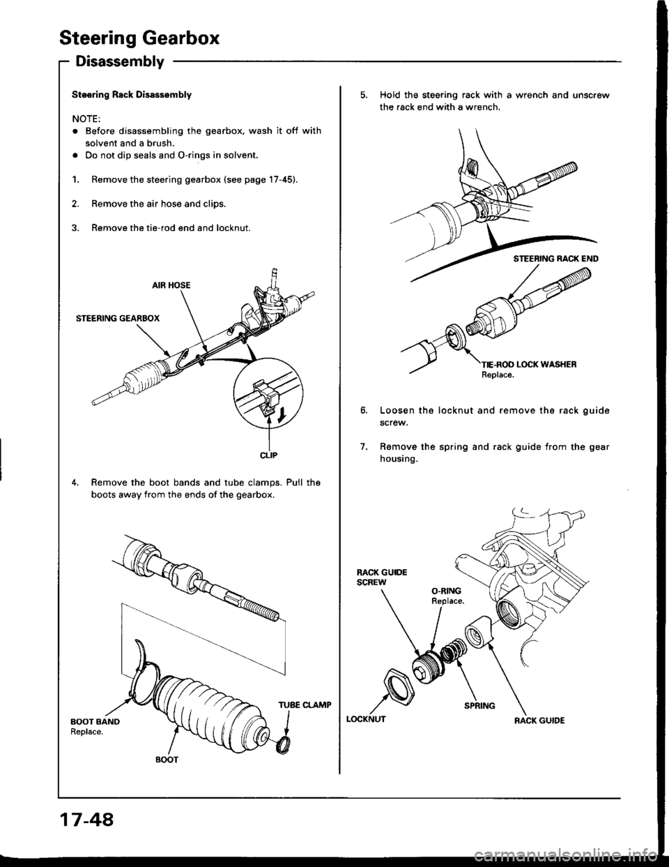
Steering Gearbox
Disassembly
Stssring Rack Disassembly
NOTE:
. Before disassembling the gearbox, wash it off with
solvent and a brush.
. Do not dip seals and O-rings in solvent.
1. Remove the steering gearbox (see page 17-45).
2. Remove the air hose and clips.
3. Remove the tie-rod end and locknut.
4. Remove the boot bands and tube clamps. Pull the
boots away from the ends of the gearbox.
CLIP
BOOT
5. Hold the steering rack with a wrench and unscrew
the rack end with a wrench.
Loosen th6 locknut and remove tha rack guide
screw.
Ramove the spring and rack guide from the gear
housing.
7.
LOCKNUTRACK GUIDE
17-48,
TUBE CLAMP
Page 660 of 1413
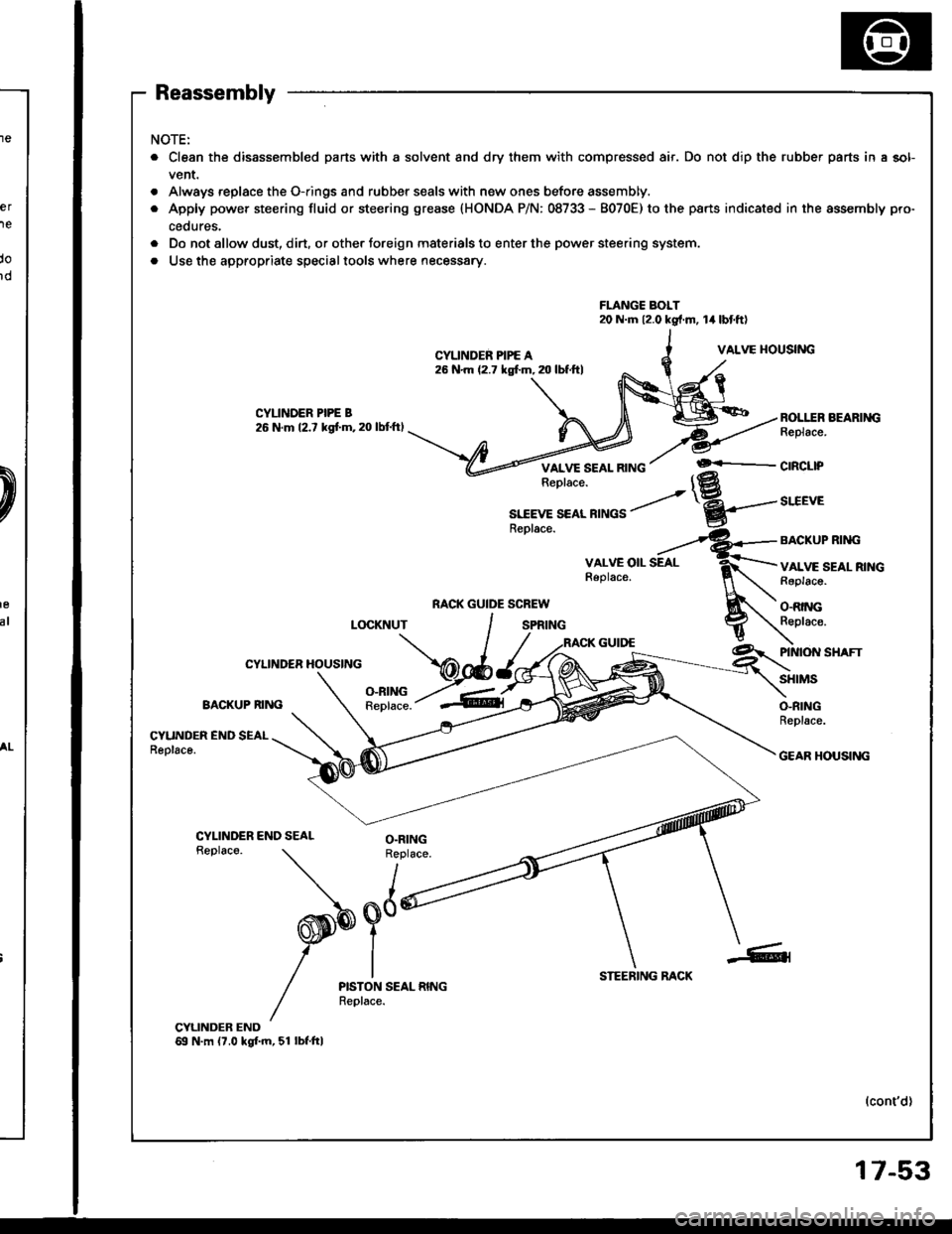
Reassembly
NOTE:
. Clean the disassembled parts with a solvent and dry them with compressed air. Do not dip the rubber parts in a sol-
vent.
. Always replace the O-rings and rubber seals with new ones before assembly.
. Apply power steering fluid or steering grease {HONDA P/N: 08733 - 8070E) to the parts indicated in the assembly pro-
cedures.
. Do not allow dust, dirt. or other foreign materials to enter the power steering system.
. Use the appropriate specialtools where necessary.
FLANGC BOLT20 N.m 12.0 kg{.m, lil lbt'ftl
CYLINDER PIPE A26 N'm (2.7 kgf.m, 20 lbf.ftl
VALVE I{OUSING
BOLI..ER BEARINGReplace.
VALVE SEAL RINGReplace.+-cncl|P
RACK GUIDE SCREW
S1IEVE SEAI RINGSReolace.
SITEVE
BACKUP RIM}
VALVE SEAL RINGRaplacs.
O.RINGReplac€.LOCKNUT
CYLINDER HOUSING
O-RINGBACKUP RING Replace.
\
PINION SHAFT
SHIMS
O-RINGReplace.
CYUNDER END SEALReolace.GEAR HOUSING
CYLINDER END SEALReplaco.O.RINGReplace.
I
x nd#$Y
IPISTON SEAL RINGReplace.
STEERING RACK
(cont'd)
17-53
Page 667 of 1413
Steering Gearbox
Reassembly lcont'd)
-4. Determine the requifed thickness of the 32 mm
shims by subtracting the clearance obtained in thestep -3 from the total thickness of the four shims.(Total thickness of the 4 shims) - (Clearance) =
Required thickness of the shims
NOTE: Select the shims so that th6 total thicknessis close to, but less than the required thickness.
Exampls:
Measu.ement is 0.28 mm (0.011 in):
0.70 - 0.28 = 0.42 mm (0.028 - 0.011 = 0.0't7 in)
The selected shims should be 0.25 mm (O.O1O in) and0.15 mm (0.005 in) in thickness.
lf the required shim thickness is 0.lO mm or less, no
shims are necessary.
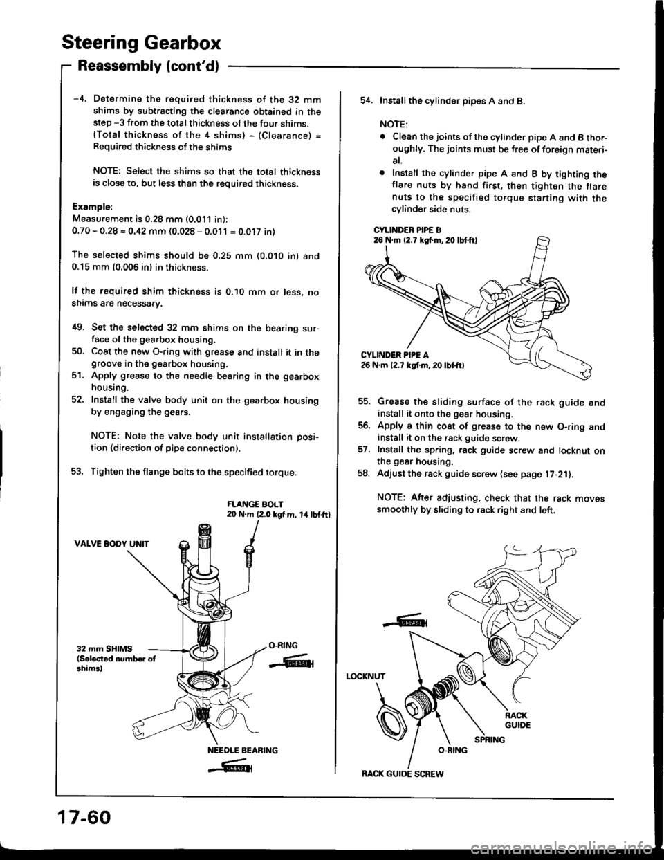
i[9. Set the selected 32 mm shims on the bearing sur-face of the g€arbox housing.
50, Coat the new O-ring with gresse and install it in thegroove in the gearbox housing.
Apply grease to the needle bearing in the gearbox
housing.
Install the valve body unit on the gearbox housing
by engaging the gears.
NOTE: Note the valve body unit installation posi-
tion (direction of pipe connection).
Tighten the flange bolts to the specified torque.
FLANGE BOLT20 N.m (2.0 kgt m, 14lbf.ft)
VALVE BODY UNIT
ct.
O-RING
-ffiti
NEEOLE BEARING
_#{
17-60
BACK GUIDE SCREW
54. Installthe cylind6r pipes A and B.
NOTE:
. Clean the joints ofthe cylinder pipe A and B tho.-oughly. The joints must be free of foreign mat€.i-
at,
o Install the cylinder pipe A and B by tighting theflare nuts by hand first, then tighten the flarenuts to the specified torque starting with thecylinder side nuts.
CYLINDER PIPE B
Grease the sliding surface of the rack guide andinstall it onto the gear housing.
Apply a thin coat of grease to the n€w O-ring andinstall it on the rack guide screw.
Install the spring, rack guide screw and locknut onthe gear housing.
Adjust the rack guide screw (see page l7-21).
NOTE: After adjusting, check that the rack movessmoothly by sliding to rack right and left.
LOCKNUT
-6t
26 N.m (2.7 kg{.m,20lbtft)
Page 668 of 1413
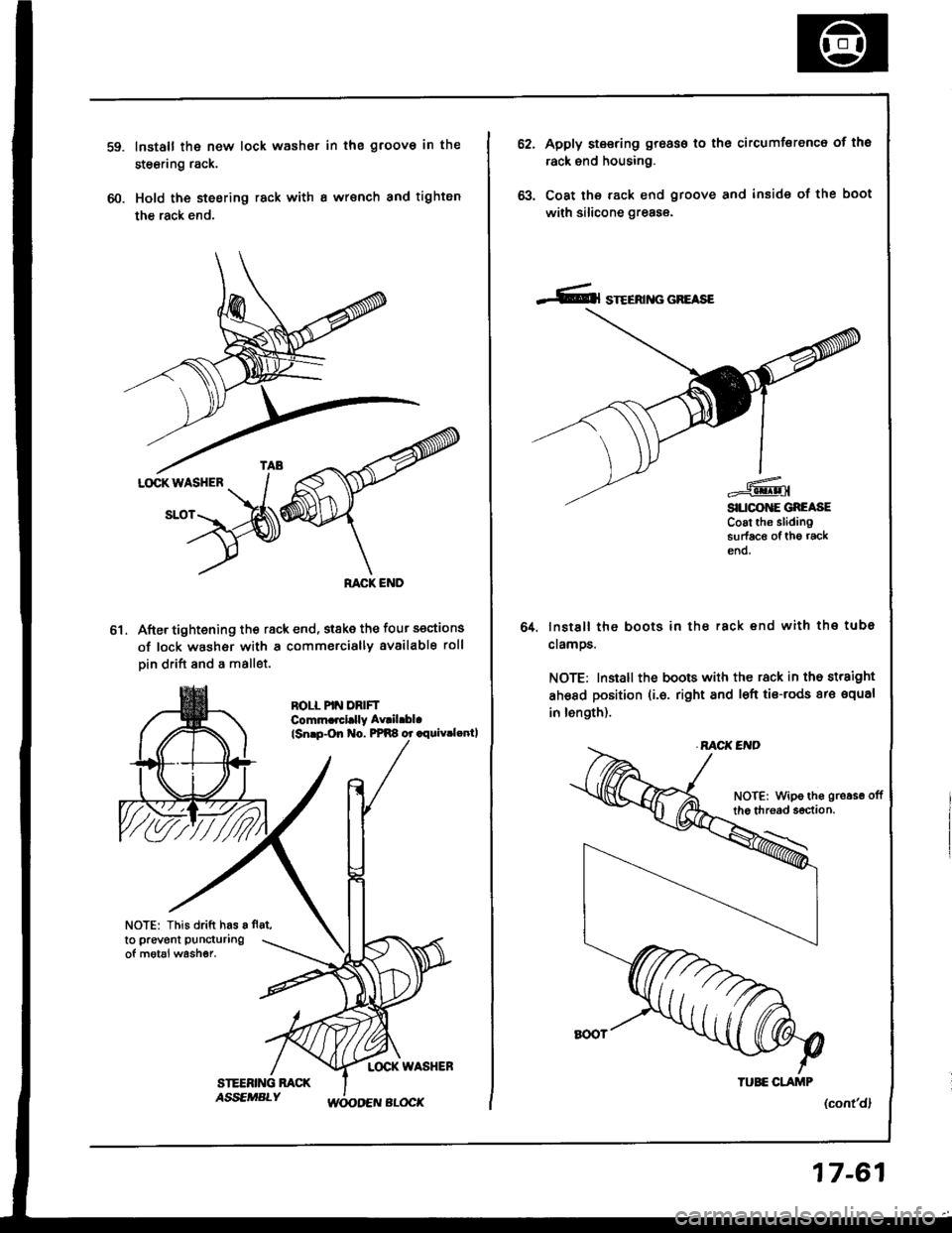
60.
Install the new lock washor in the groov€ in the
steering rack.
Hold the steering rack with I wrsnch and tighten
the rack end.
After tightening th€ rack end, stske the four sections
of lock washer with a commercially available roll
Din drift and a mallet.
ROLL PIN DRIFTComm.rcl.lly Av|il.bl.
lsnrp-On No. PPR8 or .rquiv.lenll
NOTE: This drift has a fl8t,
to prevent puncturing
of motal washer.
ol
62.Apply steering groass to the circumferenc6 of tho
rack end housing.
Coat the rack end groove and inside of the boot
with silicone greas€.
lnstsll the boots in ths rack end with the tube
clamos.
NOTE: Install the boots with the rack in the straight
ahsad position (i.6. right and l€ft tis-rods ar€ squal
in length).
(cont'dl
64.
NOTE: Wipe ths gro.se offthe thread s€ction.
TUEE CLAJTIP
17-61
Page 669 of 1413
Steering Gearbox
Reassembly (cont'dl
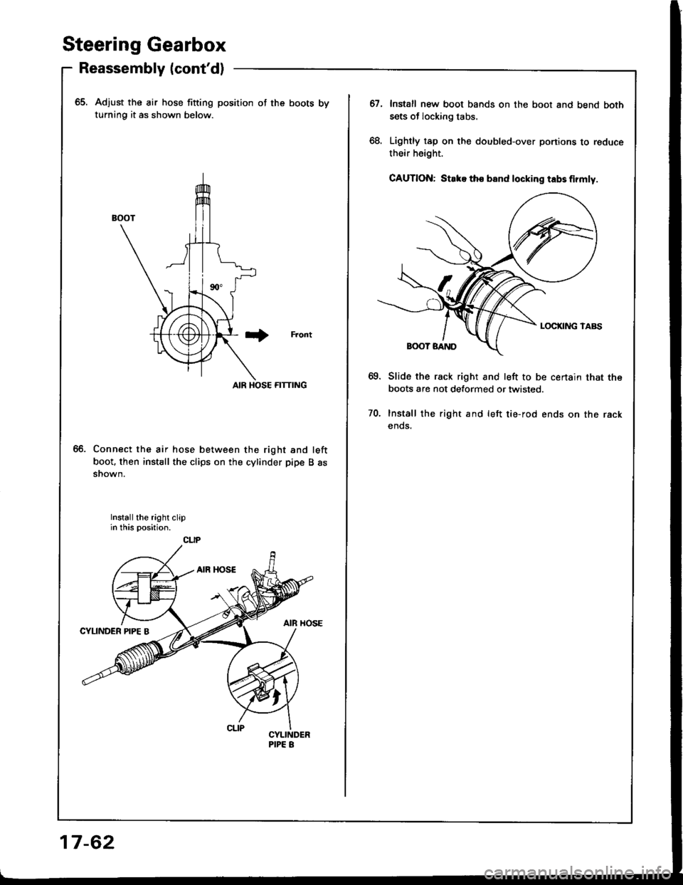
65. Adjust the air hose fitting position of the boots by
turning it as shown below.
Front
AIR HOSE FITTING
Connect the air hose between the right and left
boot. then install the clips on the cylinder pipe B assnown.
Install the right clipin this position.
CLIP
17-62
67.Install new boot bands on the boot and bend both
sets of locking tabs.
Lightly tap on the doubled-over portions to reduce
their height.
GAUTION: Stake tho band locking tabs firmly.
Slide the rack right and left to be certain that the
boots are not detormed or twisted.
Install the right and left tie-rod ends on the rack
ends.
70.
Page 671 of 1413
Steering Gearbox
Installation (cont'd)
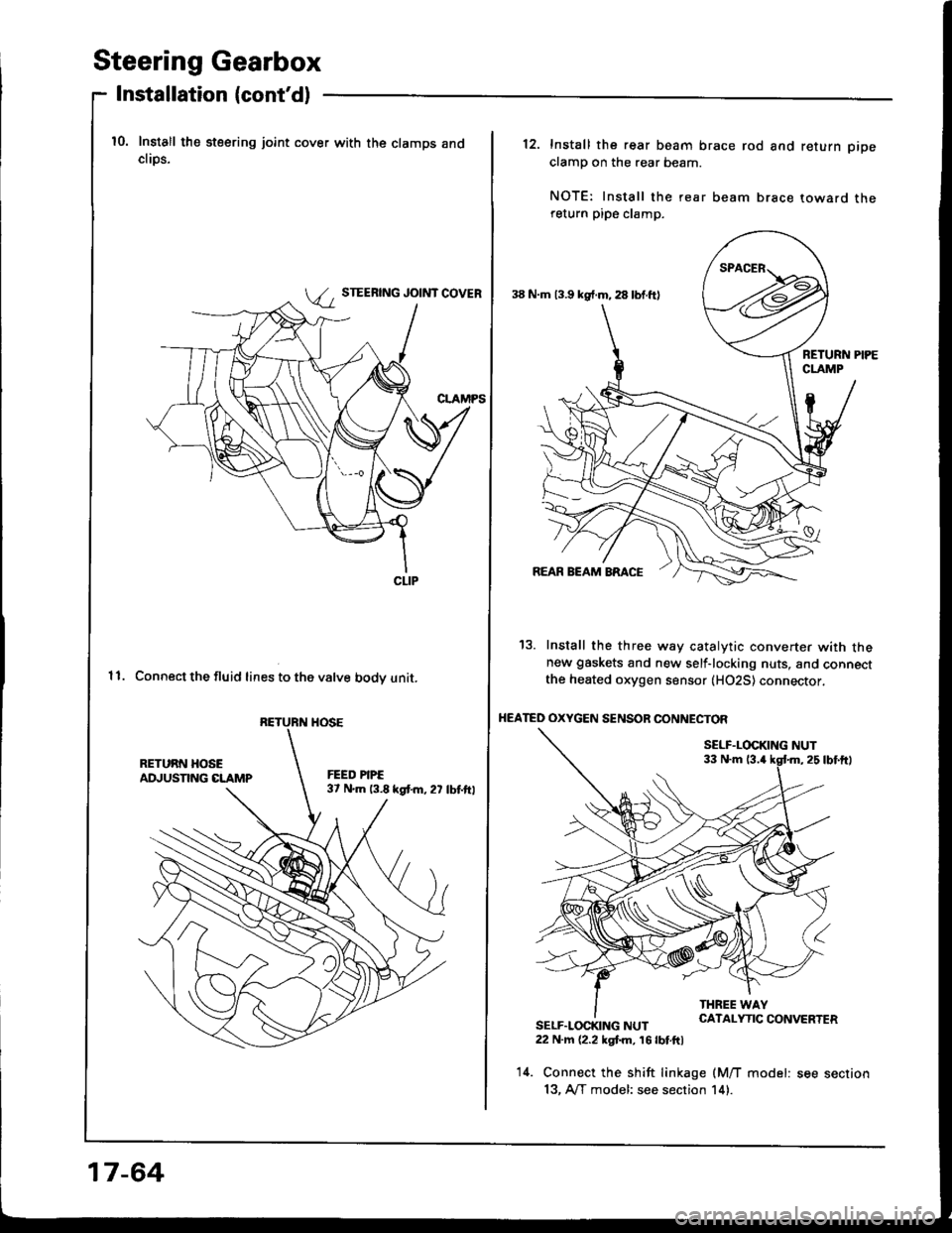
10. Install the steering joint cover with the clamps andcliDs.
STEERING JOINT COVER
11. Connect the fluid lines to the valve bodv unit.
CLIP
RETURN HOSE
17-64
38 N.m 13.9 kg{.m, 28 lbf.ft)
12. Install the rear beam brace rod and return pipe
clamp on the rear beam.
NOTE: Install the rear beam brace toward thereturn pipe clamp.
13. Install the three way catalytic converter with thenew gaskets and new self-locking nuts, and connectthe heated oxygen sensor (H02S) connector,
HEATED OXYGEN SENSOR CONNECTOF
SELF.LOCKING NUT33 N.m 13.4
SELF.LOCKING NUT22 N.m (2.2 kgt m, 16 lbt.ftl
14. Connect the shift linkage (M/T model: see section
13, A/T model: see section 14).