Cylinder HONDA INTEGRA 1998 4.G Repair Manual
[x] Cancel search | Manufacturer: HONDA, Model Year: 1998, Model line: INTEGRA, Model: HONDA INTEGRA 1998 4.GPages: 1681, PDF Size: 54.22 MB
Page 360 of 1681
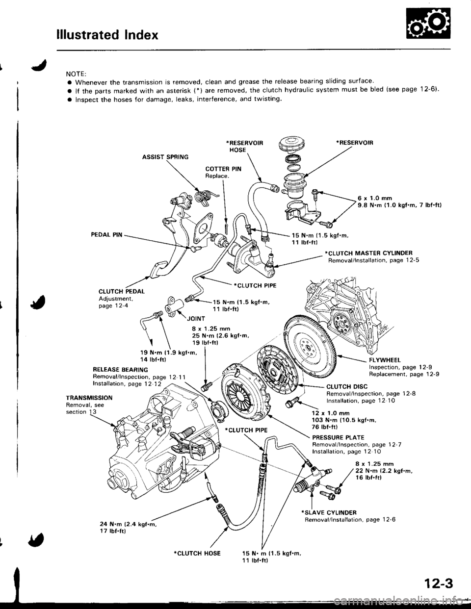
lllustrated Index
NOTE:
a Whenever the transmission is removed, clean and grease the release bearing sliding surface'
a lf the Darts marked with an asterisk (*) are removed, the clutch hydraulic system must be bled (see page 12-6).
a lnspect the hoses for damage, leaks, interference, and twisting.
*RESERVOIR
HOSE
.RESERVOIR
ASSIST SPRING
PEDAL PIN
CLUTCH PEDAL
Removal/lnspecrion, page 12 1 1fnstalfation, p,age 12 12
6 x 1.0 mm9.8 N.m 11.0 kst.m, 7 lbt'ftl
'15 N.m (1 .5 kgt.m,11 tbf.tr)
*CLUTCH MASTER CYLINDERRemoval/lnstallation, page 12-5
Adjustment,page 12 4
19 N.m 11.9 kgl.m,14 tbf.ft)
R€LEASE BEARING
15 N.m (1.5 kgf.m,11 lbf.fr)
ICLUTCH PIPE
.CLUTCH PIPE
FLYWHEELInspection, page 12-9Replacement, page 12-9
JOINT
I x 1.25 mm25 N.m {2.6 kgf.m,19 tbf.frl
I
TRANSMISSIONRemoval, see
CLUTCH DISCRemoval/lnspection, page 12-8lnstalfation, page 1 2 1O
section 1312 x 1.0 mm'103 N.m (10.5 kgl.m,76 tbf.fr)
PRESSURE PLATERemoval/lnspection, page 12 7Installation, page 12 10
8 x 1.25 mrr|22 N.m 12.2 kgt.n,16 lbf.ft)
24 N.m (2.4 kgf.m,17 tbf.tr)
15 N. m {1 .5 kgf.m,11 lbf.tr)
COTTERReplace.
I
WInl
9l
v.^- fl
*CLUTCH HOSE
Page 361 of 1681
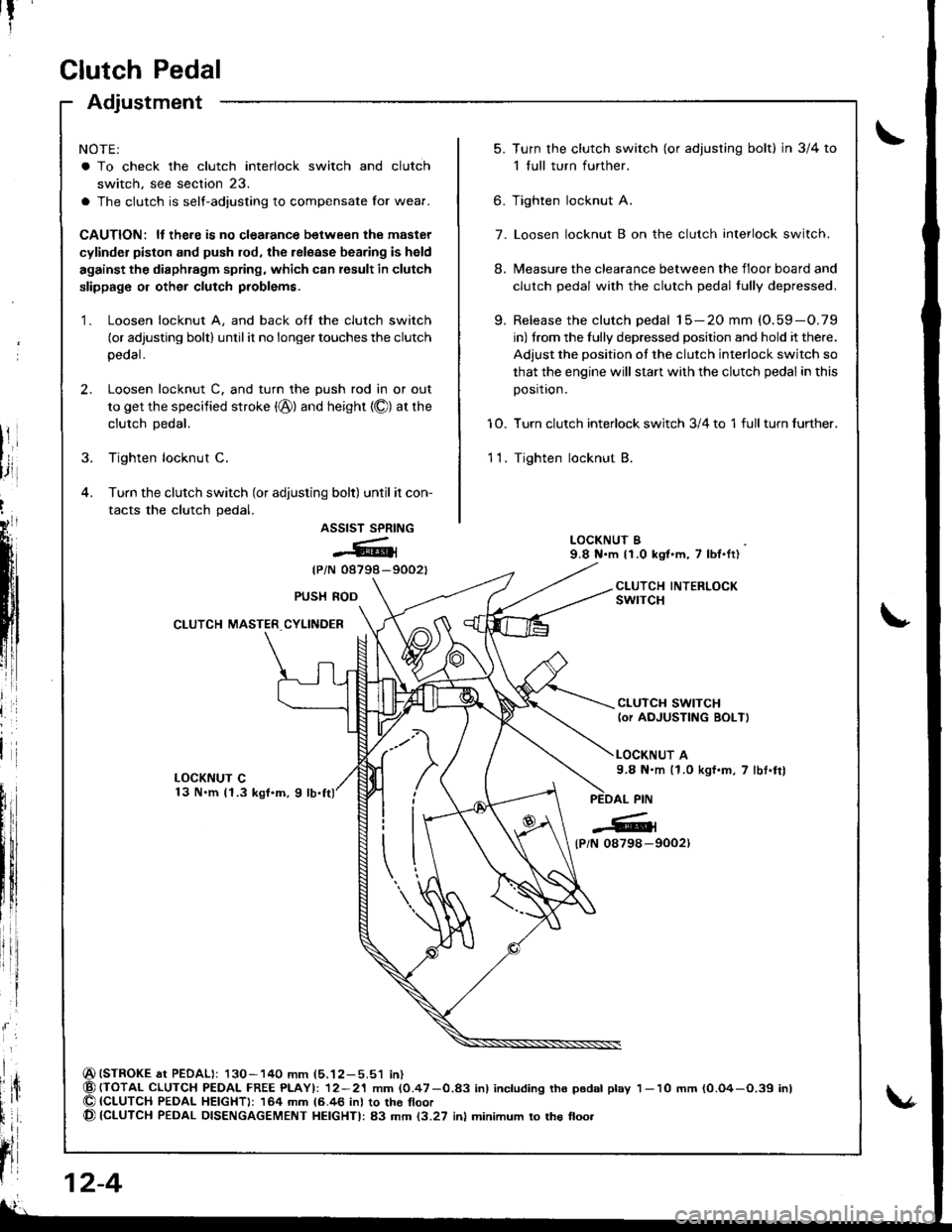
Clutch Pedal
Adjustment
NOTE:
a To check the clutch interlock switch and clutch
switch, see section 23.
a The clutch is self-adjusting to compensate Ior wear.
CAUTION: ll there is no clealance between the master
cylinder piston and push rod, the release bearing is held
against the diaphragm spring, which can result in clutch
slippage or other clutch problems.
1. Loosen locknut A, and back off the clutch switch
(or adjusting bolt) until it no longer touches the clutch
peoal.
2. Loosen locknut C. and turn the push rod in or out
to get the specified stroke (@) and height {O) at the
clutch Dedal.
3. Tighten locknut C.
4. Turn the clutch switch (or adjusting bolt) until it con-
tacts the clutch pedal.
ASSIST SPRING
@{
{PiN 08798-9002t
(STROKE at PEDAL): 130-140 mm (5.12-5.51 in){TOTAL CLUTCH PEDAI- FREE PLAYI: 12-21 mm (0.47-0.83 inl including tho p6dal play{CLUTCH PEDAL HEIGHT): 164 mm 16.46 inl to the tloor(CLUTCH PEDAL DISENGAGEMENT HEIGHTI: 83 mm {3.27 inl minimum to the floo.
t?
5.Turn the clutch switch (or adjusring bolt) in 3/4 to
1 full turn further.
Tighten locknut A.
Loosen locknut B on the clutch interlock switch.
Measure the clearance between the floor board and
clutch pedal with the clutch pedal tully depressed.
Release the clutch pedal 15-20 mm (O.59-O.79
in) from the fully depressed position and hold it there.
Adjust the position of the clutch interlock switch so
that the engine will stan with the clutch pedal in this
position.
Turn clutch interlock switch 3/4 to 1 full turn further.
Tighten locknut B.
9.
6.
7.
8.
10.
11.
LOCKNUT B9.8 N.m 11.0 kgt.m, 7 lbl.ft)
CLUTCH INTERLOCKswrTcHPUSH ROD
CLUTCH MASTER CYLINDER
CLUTCH SWITCH(or AOJUSTING BOLT)
LOCKNUT A9.8 N.m (1.0 kgf.m, 7 lbt.frl
l
{P/N 0879a-9002)
12-4
1- 10 mm (0.O4-O.39 inl
Page 362 of 1681
CAUTION:
a Do not 3pill brakefluid on the vehicle; it may damege
th€ paid; if brake fluid do63 contact th€ paint. wa3h
it otf immediately with water.
a Plug the end of the clutch pipe and reservoir hose with
a shop towel to prevent brake fluid from coming out.
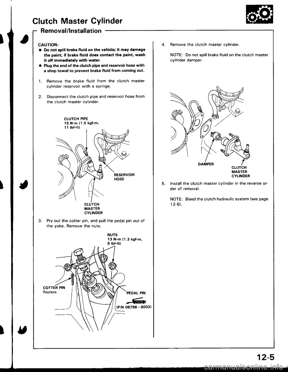
1. Remove the brake fluid trom the clutch master
cylinder reservoir with a syringe,
2. Disconnect the clutch pipe and reservoir hose from
the clutch master cylinder.
Remove the clutch master cylinder.
NOTE: Do not spill braketluid ontheclutch master
cylinder damper.
CLUTCH PIPE15 N.m {1 .5 kgf'm,11 lbt.Ir)
5.
cLulcHMASTERCYLINDER
Install the clutch master cylinder in the reverse or-
der of removal.
NOTE: Bleed the clutch hydraulic system {see page
I z-ol.cturcHMASTERCYLINDER
Pry out the cotter pin, and pull the pedal pin out of
the yoke. Remove the nuts.
NUTS13 N.m {1.3 kgt.m,9 rbf.ftl
PEOAL PIN
-6rl(P/N 08798-90021
Clutch Master Cylinder
Removal/lnstallation
2-5
Page 363 of 1681
T
fi
;ill
Slave Cylinder
Removal/lnstallation
CAUTION:
a Do not spill brakelluid onthe vehicle; it may dameg€
the paint; if brake fluid does coniaqt the paint, wash
it otf immodiaioly wilh w8ter.
a Plug the end of the clutch pipe with a shop towel to
prevent brake fluid from coming out.
-6|1, Super High Temp Urea Grease (P/N
4==? 08798- 9OO2).-='aii^5Fi: Brake Assembly Lube or equivalent rubber
grease.
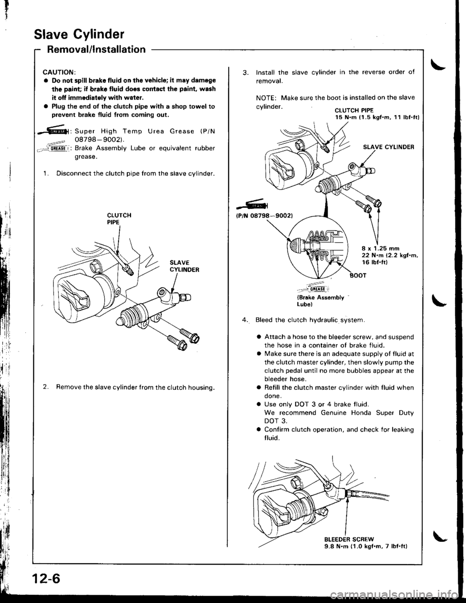
1. Disconnect the clutch pipe from the slave cylinder.
2. Remove the slave cylinder from the clutch housing.
12-6
-Gl
lP/N 08798
Install the slave cylinder in the reverse order of
removal.
NOTE: Make sure the boot is installed on the slave
.wlin.larCLUTCH PIPE15 N.m 11.5 kgt.m, 11 lbf.ttl
SLAVE CYLINDER
*9002t
I x 1.25 rnm22 N.m 12.2 kgl.m,16 lbl.lt)
.'....-..-:::-9!!!!!i
{Brake Assembly '
Lube)
Bleed the clutch hydraulic system.
a Attach a hose to the bleeder screw, and suspend
the hose in a container ot brake fluid.
a lvlake sure there is an adequate supply ot fluid at
the clutch master cylinder, then slowly pump the
clutch pedal until no more bubbles appear at the
bleeder hose.
a Refill the clutch master cylinder with fluid when
done.
a Use only DOT 3 or 4 brake tluid.
We recommend Genuine Honda Super Duty
DOT 3.
a Confirm clutch operation. and check for leaking
fluid.
Page 415 of 1681
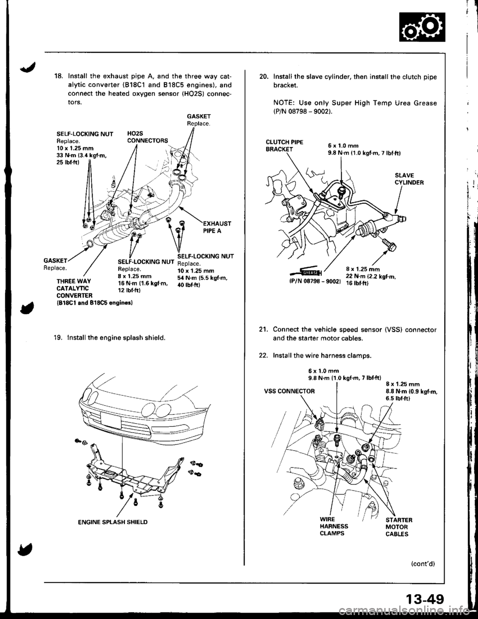
18.Install the exhaust pipe A. and the three way cat-
alytic converter {B18Cl and B18C5 engines), and
connect the heated oxygen sensor {HO2S) connec-
tors.
GASKETReplace.
HO2SCONNECTORSSELF-LOCKING NUTFeplace.10 x 1.25 mm33 N.m {3.4 kg{.m,jj25 rbr.ftl
GASKETReplace.SELF.LOCKING NUTReplace.8 x 1.25 mm'16 N.m (1.6 kgf.m,12 tbtfr)
SELF.LOCKING NUTReplace.10 x 1.25 mm54 N.m (5.5 kgt.m,40 tbt frlTHREE WAYCATALYTICCONVENTER{Bl8Cl and 8'18C5 engincsl
'19. Install the engine splash shield.
20. lnstall the slave cylinder, then instsll the clutch pipe
bracket.
NOTE: Use only Super High Temp Urea Grease(P/N 08798 - 9002).
6x1.0mm9.8 N.m 11.0 kgt m,7 lbI.ft)
SLAVECYLINDER
8 r 1.25 mm22 N.m 12,2 kotm_- 9(x)21 16 tbt.ftt
Connect the vehicle speed sensor (VSS) connestor
and the staner motor cables.
Install the wire harness clamps.
6x1.0mm9.8 N.m {1.0 kgf m, 7 lbt'ft)
VSS CONNECTOR8 x 1.25 mm8.8 N.m {0.9 kg{.m,6.s rbr.ft)
5{P/N 08798
21.
WIREHARNESSCLAMPS
(cont'd)
13-49
Page 592 of 1681
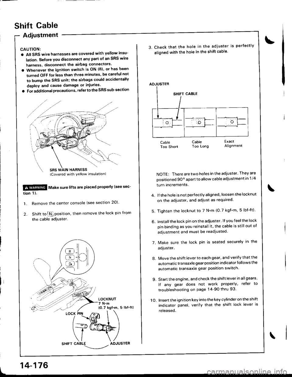
Adiustment
CAUTION:
a All SRS wile harnesses are covered with yellow insu-
lation. Belore you disconnect any part ol an SRS wire
harness, disconnect the akbag connectors'
a Whenever the ignition switch is ON (ll), or has been
tumed OFF tol less than three minutes, be caletul not
to bump the SRS unit; the airbags could accidentally
deploy and cause damage or injuries'
a For additionalprecautions, referto the SRS sub-section
SBS MAIN HARNESS(Covered with yellow inslrlationl
$!@ rtl"t . "ure lifts are placed plope y lsee sec-
tion 1 l.
'1. Remove the center console lsee section 20)'
2. Snitt to $ position, then remove the lock pin lrom
the cable adjuster'
LOCKNUT7 N.m10.7 kgf.m, 5 lbf.fl)
t
]H
@
@
@
{l
LOCK PIN
14-176
shift cable
3. Check that the hole in the adjuster is perfectly
sligned with the hole in the shift cable'
CableToo Short
NOTE: There are two holes in the adjuster. They are
positioned 9Oo apart to allow cable adiustment in 1/4
turn Incremenrs.
4. lJ the hole is not per{ectly aligned, loosen the locknut
on the adjuster, and adiust as required.
5. Tighten the locknut to 7 N'm (0.7 kgf'm, 5lbf'ftl
6. Installthe lock pin on the adiuster. lI you feelthe lock
pin binding as Vou reinstall it, the cable is still out ot
adjustment and must be readjusted.
7. [/ake sure the lock pin is seated securely in the
aoJusrer.
8. Move the shift lever to each gear, and verify that the
automatic transaxle gear position indicator follows the
automatic transaxle gear position swatch.
9. Start the engine, and check the shift lever in allgears'
lf any gear does not work properly, refer to
troubleshooting on page 14-90 thru 93.
10. Insert the ignition key into the key cylinder on the shift
indicator panel, verify that the shift lock lever is
released.
CableToo Long
ExactAlignment
\
ADJUSTER
Page 651 of 1681
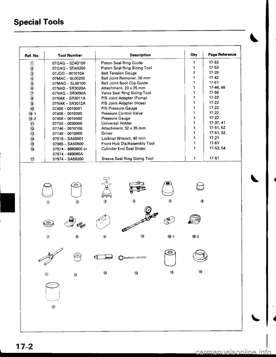
SpecialTools
{
\
\
17-2
Ref. No. I Tool NumberDsscriptionOty I Pags Reterenc.
o
@
@
o
@
@
@
@
@
@-1
@-2
o6:^
@
@
@
@
@
07GAG - SD40100
07GAG - SD40200
07JGG - 001010A
07MAC - S100200
07MAG - S100100
07NAD - SR3020A
OTNAG _ SR3OgOA
OTNAK - SR3O11A
OTNAK - SR3O12A
07406 - 0010001
07406 - 0010300
07406 - 0010400
07725 - 0030000
07746 - 0010100
07749 - 0010000
07916 - SA50001
07965 - SA50500
07974 - 6890800 or
07974 - 6890804
07974 - SA50200
Piston Seal Ring Guide
Piston Seal Ring Sizing Tool
Belt Tension Gauge
Ball Joint Remover, 28 mm
Ball Joint Boot Clip Guide
Attachment, 23 x 25 mm
Valve Seal Ring Sizing Tool
P/S Joint Adapter (Pump)
P/S Joint Adapter (Hose)
P/S Pressure Gauge
Pressure Control Valve
Pressure Gauge
Universal Holder
Attachment, 32 x 35 mm
Driver
Locknut Wrench. 40 mm
Front Hub Dis/Assembly Tool
Cylinder End Seal Slider
Sleeve Seal Ring Sizing Tool
'I
1
1
1
1'|
1,l
I
1
1
1'I
'l
1
1
1
1
1
't7-53
17-53't]-20
11-42
17 -51
17 -46, 4A
17-50
17-37, 41
11-51,52't1-51,52
17 -2'�1
17 -6'l
17-53. 54
17-51
o
L'4,
o
€)
-g)c-J 8p
@
@
6i
(9')\E/'
@-t
a
6
ffi
@-z
d--E ia*=-
o
l-l
t..-_-.r
A)
@@@
\
Page 653 of 1681
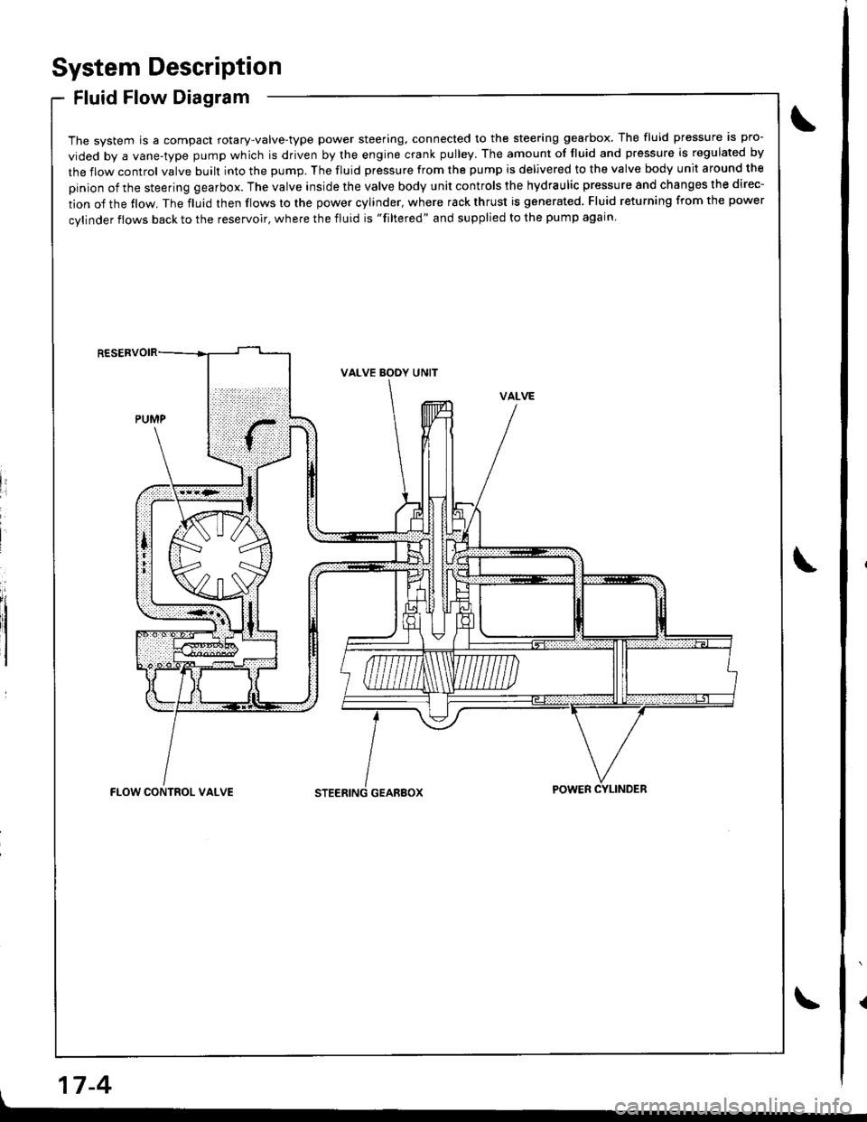
System Description
Fluid Flow Diagram
The system is a compact rotary-valve-type power steering, connected to the steering gearbox. The fluid pressure is pro-
vided by a vane-type pump which is driven by the engine crank pulley. The amount of fluid and pressure is regulated by
the flow control valve built into the pump. The fluid pressure from the pump is delivered to the valve body unit around the
pinion of the steering gearbox. The valve inside the valve body unit controls the hydraulic pressure and changes the direc-
tion of the tlow. The fluid then flows to the power cylinder, where rack thrust is generated. Fluid returning from the power
cylinder flows back to the reservoir, where the fluid is "filtered" and supplied to the pump again
li
I
VALVE BODY UNIT
GEARBOXFLOW CONTROL VALVEPOWER CYLINDER
17-4
Page 657 of 1681
System DescriPtion
Steering Gearbox
it
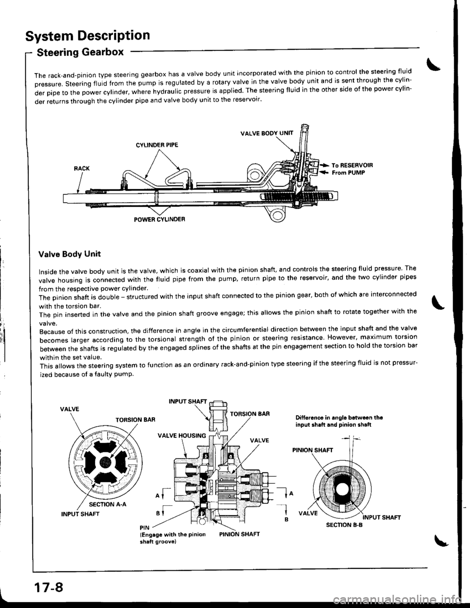
The rack,and-pinion type steering gearbox has a Valve body unit incorporated with the pinion to control the steering fluid
pressure. steering fluid from the pump is regulated by a rotary valve in the valve body unit and is sent through the cylin-
derpipetothepowercy|inder,wherehydrauIicpressureisapp|ied.Thesteeringf|Uidintheothersideofthepowercy|in-
der returns through the cylinder pipe and valve body unit to the reservoir'
Valve Body Unit
Inside the valve body unit is the valve, which is coaxial with the pinion shaft, and controls the steering fluid pressure The
valve housing ls connected wirh the fluid pipe from the pump. return pipe to the reservoir, and the two cylinder pipes
from the respective power cylinder.
The pinion shaft is double - structured with the input shaft connected to the pinion gear, both of which are interconnected
with the torsion bar.
The pin inserted in the valve and the pinion shaft groove engage; this allows the pinion shaft to rotate together with the
Because of this construction. the difference in angle in the circumferential direction between the input shaft and the valve
becomes larger according ro the torsional strength ol the pinion or steering resistance. However. maximum torsion
between the shafts is regulated by the engaged splines of the shafts at the pin engagement section to hold the torsion bar
within the set value.
This allows the steering system to function as an ordinary rack-and-pinion type steering if the steering iluid is not pressur-
ized because of a faulty PumP.
VALVE
INPUT SHAFT
INPUT SHAFT
VALVE XOUSING
of
'I
lEng.ge with th€ Pinionshaft groove)
TORSION BARDift6rance in angle b6twe€n theinput ih.ft.nd pinion shalt
la-l
B
VALVE BODY UN]T
SECNON B.B
17-8
Page 658 of 1681
INPUT SHAFT
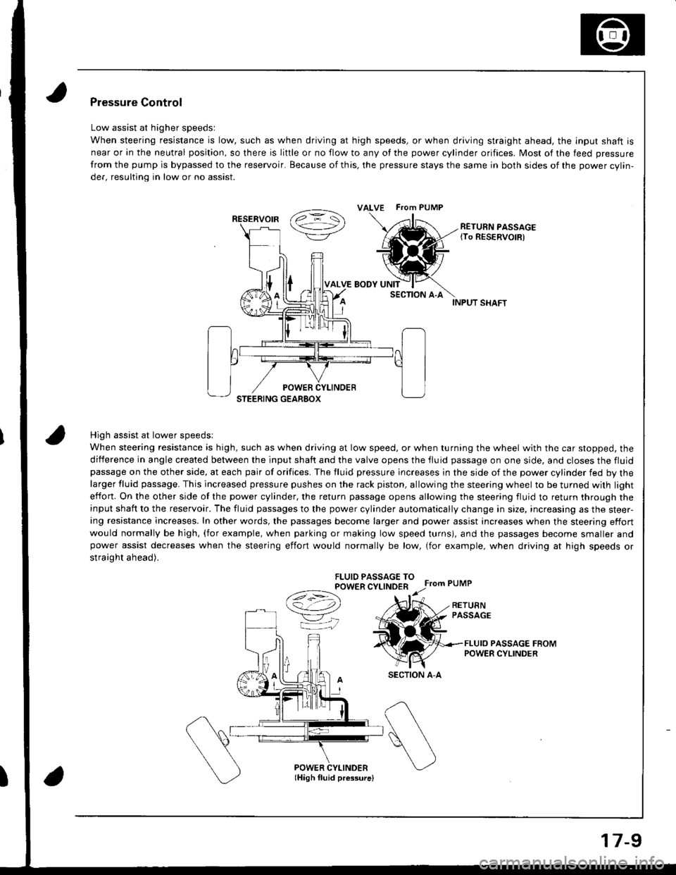
High assist at lower speedsl
When steering resistance is high, such as when driving at low speed, or when turning the wheel with the car stopped, the
diiference in angle created between the input shaft and the valve opens the tluid passage on one side, and closes the fluidpassage on the other side, at each pair of orifices. The fluid pressure lncreases in the side of the power cylinder fed by thelarger fluid passage. This increased pressure pushes on the rack piston, allowing the steering wheel to be turned with light
effon. On the other side of the power cylinder, the return passage opens allowing the steering fluid to return through theinput shaft to the reservoir. The fluid passages to the power cylinder automatically change in size, increasing as the steer-ing resistance increases. In other words, the passages become larger and power assist increases when the steering effort
would normally be high, (for example, when parking or making low speed turns), and the passages become smaller andpower assist decreases when the steering effort would normally be low, (for example, when driving at high speeds or
straight ahead).
FLUIO PASSAGE TOPOWER CYLINDER
Ce) r.r;
VK
Pressure Control
Low assist at higher speedsl
When steering resistance is low, such as when driving at high speeds, or when driving straight ahead. the lnput shaft is
near or in the neutral position, so there is liftle or no flow to any of the power cylinder orifices. Most of the feed pressure
from the pump is bypassed to the reservoir. Because of this, the pressure stays the same in both sides of the power cvlin-
der, resulting in low or no assist.
RETURN PASSAGE{To RESERVOIR)
POWER CYLINDERlHigh fluid pressurelI
ALVE FTom PUMP
RESERVOIR
SECTION A-A
17-9