cable HONDA INTEGRA 1998 4.G Workshop Manual
[x] Cancel search | Manufacturer: HONDA, Model Year: 1998, Model line: INTEGRA, Model: HONDA INTEGRA 1998 4.GPages: 1681, PDF Size: 54.22 MB
Page 1336 of 1681
Precautions/Procedu res
SRS Unit Precautions
Take extra caro when painting or doing body work in
the area below the dashboard. Avoid direct exposure
of the SRS unit or wiring to heat guns, welding, or
spraying equipment.
Disconnect the airbsg connector(s) before discon-
necting SRS harness connectors (see page 23-2851.
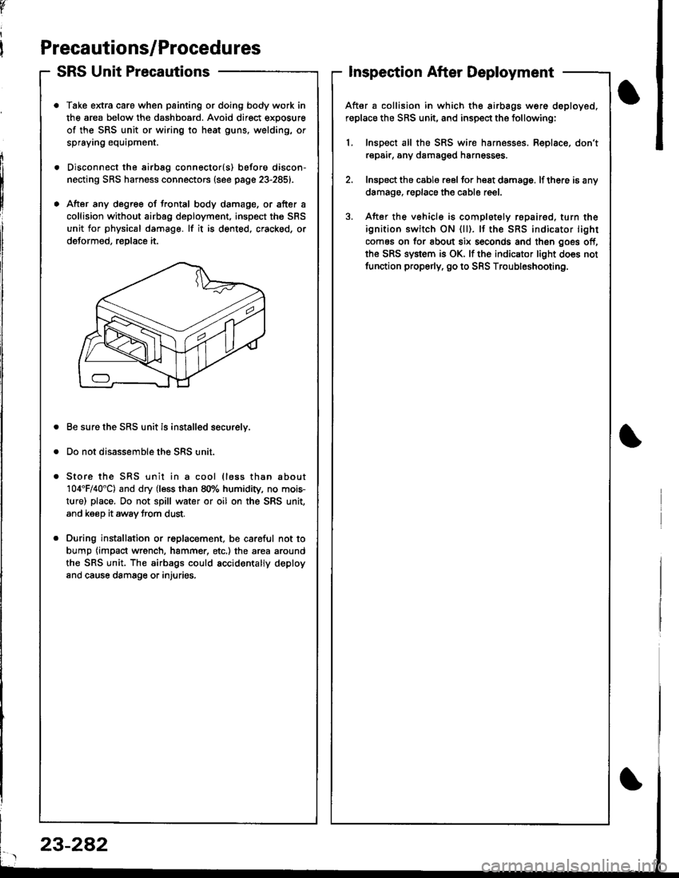
After any degree of frontal body damage, or after a
collision without airbag deployment, inspect the SRS
unit for physical damage. lf it is dented, cracked, or
deformed, reDlace it.
Be sure the SRS unit is installed securelv.
Do not disassemble the SRS unit.
Store the SRS unit in a cool (lass than about
104'F/40"C) and dry (less than 80% humidity, no mois-
ture) place, Do not spill water or oil on the SRS unit,
and keeD it awav trom dust.
During installation or r6placement, be careful not to
bump {impact wrench, hammer, etc.) the area around
the SRS unit. The airbags could accidentally deploy
and cause damsge or injuries,
v
Inspection After Deployment
After a collision in which the airbags w6re deployed,
replace the SRS unit, and inspect the following:
1, Inspect all the SRS wire harnesses. Replace, don't
repair, any damaged harnesses
2. Inspect the cable reel for heat damage. lf there is any
damage. replace the cable reel.
3. After the vehicle is completely repairod, turn the
ignition switch ON {ll). lf the SRS indicator light
comes on for about six seconds and then goes off,
the SRS system is OK. lf the indicator light does not
function properly. go to SRS Troubleshooting.
23-282
Page 1339 of 1681
Disconnecting the Airbag Connector(s)
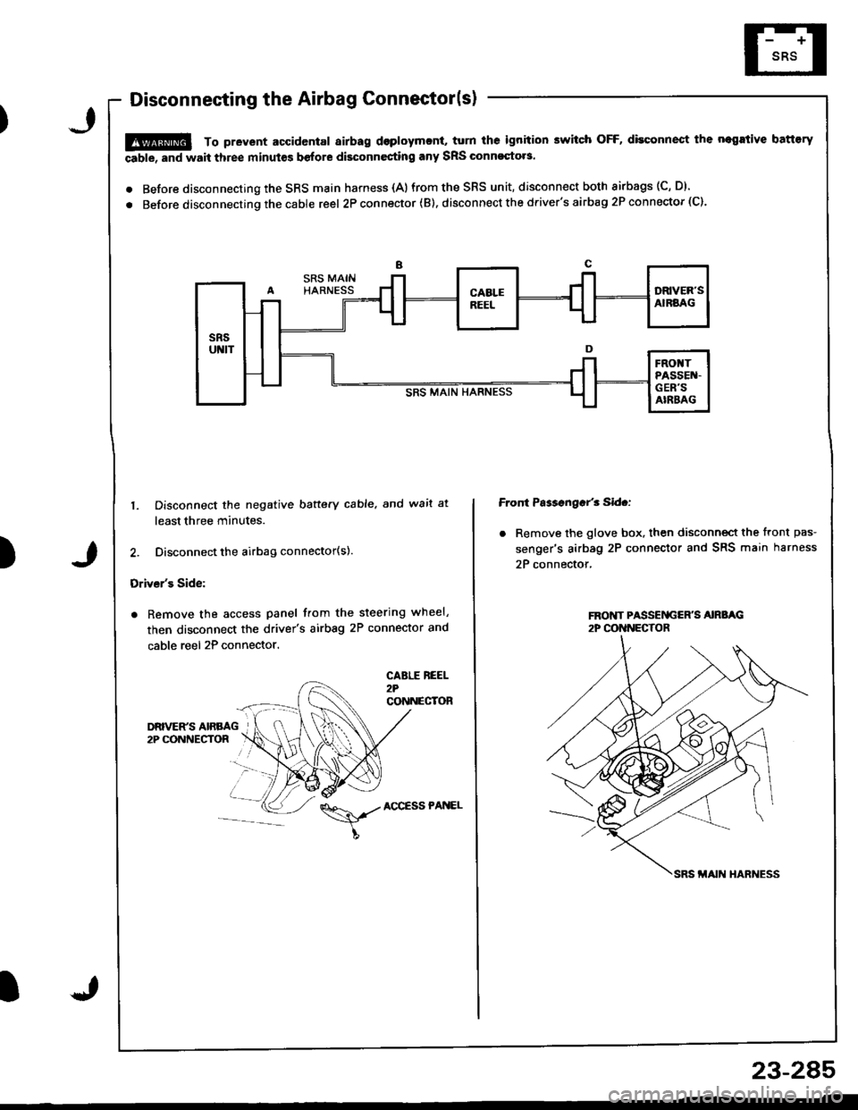
!@ To prevent accidental airbag dsploymcnt, turn ths ignition switch OFF, disconnect the negrtive battory
able, and wait three minut€s before disconnesting any SRS Glnnoqto.s.
. Before disconnecting the SRS main harness {A)from the SRS unit, disconnect both airbags (C, D).
. Before disconnecting the cable reel 2P con nector ( B). disconnect the driver's airbag 2P connector (C).
)
1. Disconnect the negative baftery cable. and wait at
least three minutes.
2. Disconnect the airbag connector(s).
Driver's Side:
. Remove the access panel from the steering wheel,
then disconnect the driver's airbag 2P connector and
cable reel 2P connector.
CABLE REEL2?CONNECTOR
Front Ps$sngar'3 Sid.:
. Remove the glove box. then disconnect the front pas-
senger's airbag 2P connector and SRS main harness
2P connector,
\,./AccEssPANEL
23-2A5
Page 1340 of 1681
Precautions/Procedures
Steering-related Precautions
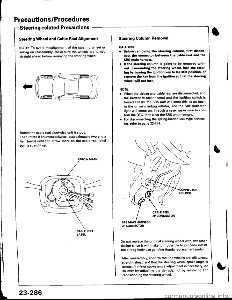
Steering Wheel and Gable Reel Alignment
NOTE: To avoid misalignment of the steering wheel or
airbag on reassembly. make sure the wheels are turned
straight ahead before removing the steering wheel.
Rotate the cable reel clockwise unit it stops.
Then rotate it counterclockwise (approximately two and a
half turns) until the arrow mark on the cable reel label
points straight up.
ARROW MARK
23-286
Steering Column Removal
CAUTION:
. Before romoving the steoring column, lirst di3con-
nect ths connector bctwoen tho csble rsal and the
SBS main harneEs.
. lf the steeting column is going to be rsmoved with-
out dismounting the steering wheel, lock the steer-
ing by iurning the ignition k6y to o'LOCK position' or
remove tho key lrom thc ignition ro that the steering
wheel will not turn.
NOTE:
When the airbag and cable reel are disconnected, and
the battery is reconnected and the ignition switch is
turned ON (ll), the SRS unit will store this as an open
in the driver's airbag inflator, and the SRS indicator
light will come on. In such a case, make sure to con-
firm the DTC, then clear the SRS unit memory.
For disconnecting the spring-loaded lock type connec-
tor, refer to page 23-284,
SRS MAIN HARNESS2P CONNECTOR
Do not replace the original steering wheel with any other
design since it will make it impossible to properly install
the airbag {only use genuine Honda replacement parts).
After reassembly. confirm that the wheels are still turned
straight ahead and that the steering wheel spoke angle is
correct, lf minor spoke angle adjustment is necessary, do
so only by adjusting the tie-rods, not by removing and
repositioning the steering wheel.
L
Page 1349 of 1681
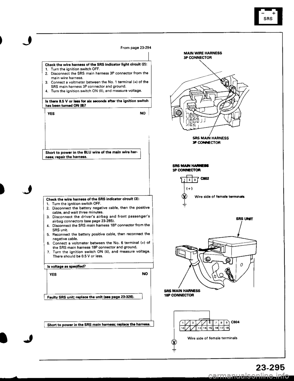
Chocktho wire h.mcas ol thc SRS Indicrtor light clrcuh l2):1. Turn the ignition switch OFF.2. Disconnect the SRS main harn€ss 3P connoctor from the
main wire harness.3. Connect a voltmeter between the No. '1 terminal {+)oltheSRS main harness 3P connector and ground,1. Turn the ignhion switch ON {ll), and measure voltag€
Ir th.rc 8.5 V or 16 toa aar t cord! tftcr rh. ignhion twitch
Shon to pow.r in th. BLU wi.o of lh. m.ln wir. h.r'
MAIN WIRE HAFNESS3P CONNECTOR
SAS MAIN HARNESSt @aa-cTof,
SRa m t{ ruE3P OOt{tCClc
)
c&
Wire sid6 of lemrla tarminaL
n00m.l I
Ch€ck lh. wir. h.rn.r. of thc SRS indic.tor circuit l3l:
1. Tlrn the ignition switch OFF.2. Oisconnoct the b8ttery negativ€ cable, then the positivo
cable, and wait throe ftinutes.
3. Disconnect the driver's airbag and front passenger's
airbag connectors (see page 23-285t'
4. Disconnect the SRS main harness 18P connector trom tho
SRS unit.5. Fsconnect the battery Dositivo cable, th€n reconnect th€
negative cable.6. Connect a voltmeter bettve€n the No. 6 terminal (+) of
th6 SRS main harness 18P connector and ground.
7. Turn the ignition switch ON (ll), and moasuro voltage.
Th€r6 should be 0.5 V or less
lr voltlsr .3 !9.cifi.d?
YESNO
F.ulty SRS unit; .cplrct th. unh {... prg. 23'326).
Shon to powe. in the SRS mrin hrtne*t taplrc.lha hmaat.
SRS UJ{'T
Wke side of temale terminals
23-295
Page 1350 of 1681

Troubleshooting
The SRS Indicator Light Doesnt Go Off
CAUTIOi{: Whenever the ignition switch is ON (ll). or
h.s bGGn turned OFF for less than three minutes. be
crrclul noi to bump the SRS unit; the airbags could
lcci{tcntrlly deploy and cause damage or iniuries.
(A)
1o page 23-297
Try to reproduce the SRS indic.tor l;ght;l. Erase the DTC memory (see page 23-289).2. Turn the ignition switch ON (ll), and check that the SRSandicator light comes on lor about six seconds and thenooes off,
Ooes the SRS indicetor light stay on?
NOYES
Intermittc t failu.e, sydem is OK dt this time. Sec Troublo-shooting lntermitteirt Failuros on p.qe 23-28!1.
Check tho No. 23 {10 A) fuse:1. Turn the ignition switch OFF-2. Check for blown No. 23 110 A) fuse in the unde.dashfuse/relay box.
ls the luse OK?
YESNO
Roplsce the f!se, and eresc the memory1. Replace the No. 23 (10 Alfuse.2. Erase the DTC memory (see page 23-289).3. Turn the ignition switch ON (ll).
Does th6 SRS indicator light go off after rix socond6?
I YEs No
I
ENO
Contilm the DTC, and continuo troubleshooting.
Check tor an open in ths SRS main hlrna3r (VB tinc):1- Disconnect the battery negative cable. thon disconnectthe positive cable, and wait tor three mrnures.2. Disconnect the driver's and front passenger's airbag con-nector (see page 23 285).3. Disconnect the SRS main harness 18P connector fromthe SRS unit.a. Reconnect the battery positive cable, then reconnect thenegative cable.5. Connect a voltmeter between the No. 3 terminal (+) otthe SRS main harness 18P connector and ground.6. Turn the ignition switch ON {ll).
ls th.re bettery vohaqe?
YES
Open in th. SRS msin h.rness (VB linc); roptrca tha
NO
No.23110 Al FUSEUNOER.DASHFUSE/RELAY AOX
SRS UNIT
SRS MAIN HARI{ESS 18P COI{I{ECTOR
Page 1355 of 1681
)
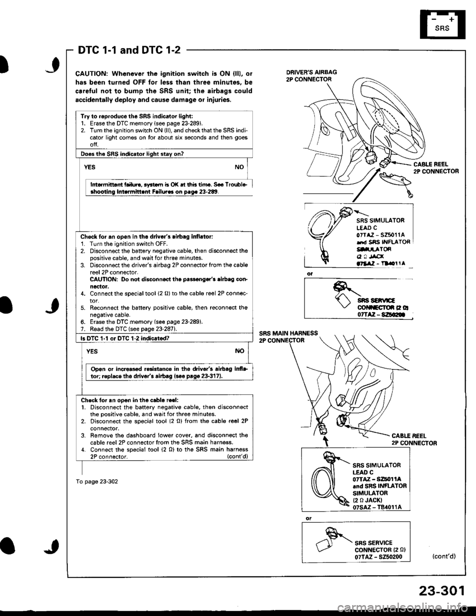
DTC 1-1 and DTC 1-2
CAUTION: Whenever the ignition switch is ON {lll, or
has been turned OFF for less thsn three minutes, be
ca.eful not to bump the SRS unit; the airbags could
accidentally deploy and cause damage or iniuries.
CABLE REEL2P CONNECTOR
SRS SIMULATORL€AD CoTtaz - s6011Alrd Sns IYFLATORg.prToR
o ! Jrcxatllil - n olrl
*.t sns savE\,' colltcroe c o07TAZ-8E@
CABLE BEEL2P CONNECTOR
SRS SERVICEGoNNECTOR (2 0l
07TAZ - 5250200(cont'd)
Try to roproduce the SRS indicator light:1. Erase the DTC memory lsee page 23-289).2. Turn the ignition switch ON (ll), and check that the SRS indicator light comes on tor about six seconds and then goes
ofJ.
Do€s the SRS indicator light stay on?
YES
h6rmittar'rt Lalul!, 3yrtdll b o|( rt thb tiiru. 5€6 lroubl6-ahootino lmarmitlant Failura. on o.oa 23-289.
Chock fo. an opGn in the dlivgl's cirbag infirtor:'1. Turn the ignition switch OFF.2. Disconnect the battery negative cable, then disconnect thepositive cable, and wail for thrce minutes.3. Disconnect the driver's airbag 2P connectorlrom th€ cablereel 2P connector-CAUTION: Do not disconnoct tho palF€nger'r .ilb.g con-nector.4. Connect the sDecial tool 12 o) to the cable reel 2P connec-tor.5. Reconnect the bsftery positive cable, then reconn€ct thonegative cable.6. Erase the DTC memory (se€ page 23-289).7. Bead the DTC (see page 23-2811.
ls DTC 1-1 oI DTC 1-2 indic.tod?
YESNO
Opon or incro8od r.rist.nco in tho driv6.'3 airbag inf+
lor; replacs tho drivor'3 rirb.g lsoe prgg 23-317).
Ch.ck for an op6n in the cablo re.l:1. Disconnect the battery negativo cabl6, thon disconnectthe positive cable, and wait for three minutes.2. Disconnect the soecial tool (2 o) from rhe cable reel 2Pconnector.3. Remove the dashboard lower cover. and disconnoct thecable reel2P connectorfrom the SRS main harness.4. Connect tho special tool (2 0) to thg SRS main harness2P connector. (cont'dl
To page 23-302
SRS SIMULATOR|.EAO C07TAZ - Si4tor lAand SRS INFLATORSIMULATOR(2 0 JACK)
23-301
Page 1356 of 1681
Troubleshooting
DTC 1-1 and DTC 1(cont'd)lJlv r-r o
From p.ge 23-301
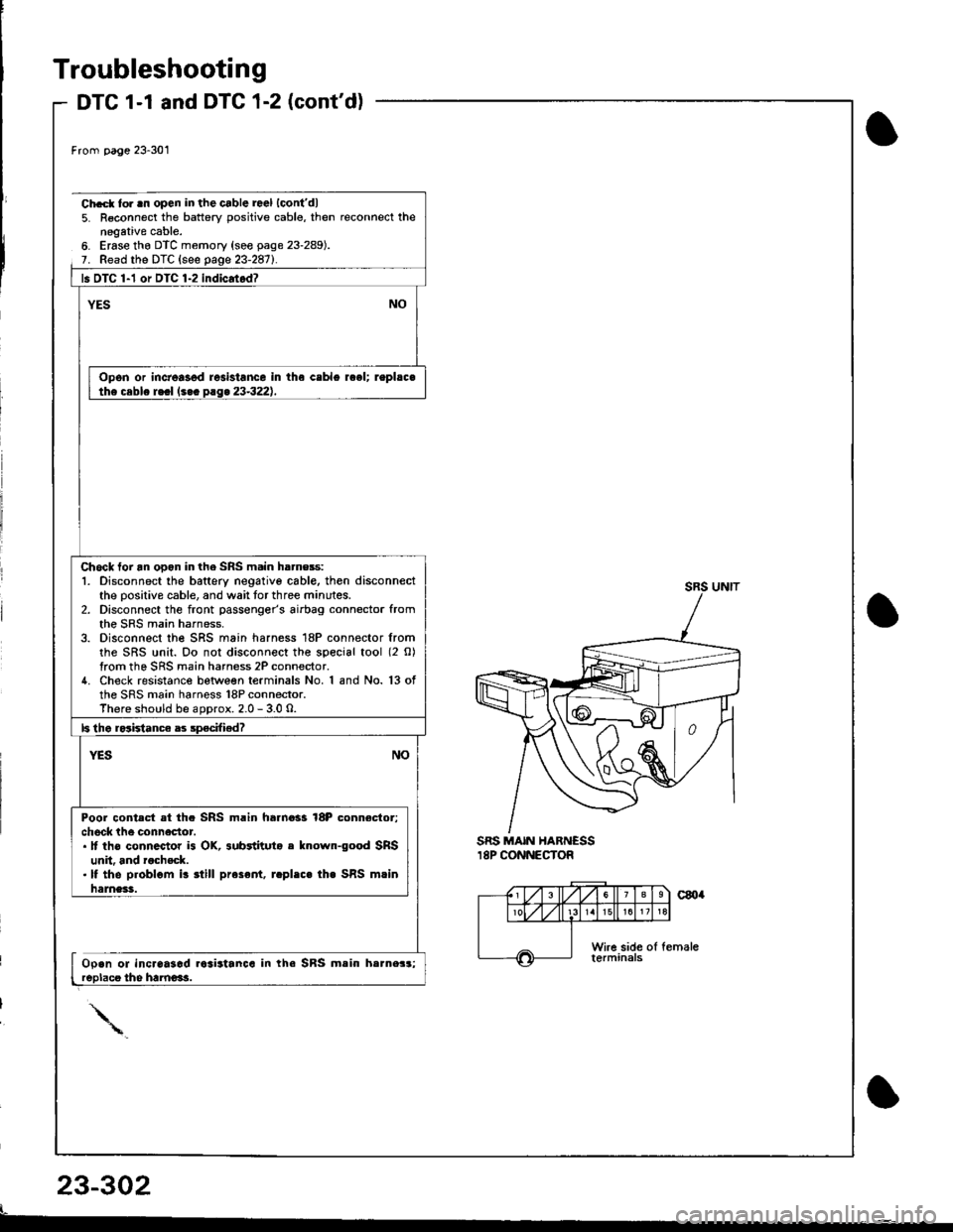
SRS MAIN HARNESSI8P CONNECTOR
Ch.cl to. .n open in the cable rael lcont'dl5. R€connect the battery positive cable, then reconnect thenegative cable.6. Erase tho DTC memory (see page 23-289).7. Read the DTC {see qaqe 23-2871.
ls OTC 1-1 or DTC 1-2 indicatod?
YESNO
Opon or increasod resistance in the ceble rcel; repl.c.the ceble re.l (s.c p.g. 23-322),
Chock to. an ooon in the SRS m.in h.rness:1. Disconnect the battery negativo cable, then disconnectthe oositive cable, and wait tor three minutes.2. Disconnect the front passenger's airbag connector fromthe SRS main harness.3. Disconnect the SRS main harness 18P connector fromthe SRS unit. Oo not disconnect the special tool (2 O)from the SRS main harness 2P connector.4. Check resistance between terminals No. 1and No. 13ofthe SRS main harness 18P connector.There should be aoorox. 2.0 - 3.0 o.
b tho rodstanca as specifiedT
YESNO
Poor conted at th. SRS m.in harnoss l8P connector;ch6ck the connector.. It ths conn.ctor is OK, 3ubrtituto e known-good SRSunit. and rachsck.. It the p.oblom i! itill preser|t, r.pl.c. th. SRS mrinhames3.
Open ol incraaiad.cairtanca in the SRs mein herne3reolacs the hamoi!.a;
23-302
t-
Page 1357 of 1681

DTC 1-3
)
CAUTION: When€ver the ignition 3witch is ON (ll), or
has been turned OFF for le3s lhan three minute3, be
careful not to bump the SRS unit; the airbags could
accidontally d€ploy and cause damage or iniuries.
Chcck for a short to anothor wiro in the driver's airbag inlla-tor:1. Turn the ignition switch OFF.2. Disconnect the battery negative cable, then disconnectthe positive cable, and wait tor three minutes.3. Disconnect the driver's airbag 2P connector from thecable reel 2P connector.CAUTION: Do not diaconnocl the p.sseng.r'5 !irbaOconnoctor.4. Connect the special tool {2 o} to the cable reel 2P connec'tor,5. Reconnect the battery positive cable, then reconnect thenegative cable.
SRS SIMULATORLEAD C0?TAZ - SZ5011Aand SRS INFLATORSIMULATORt2 0 JACKI07SAZ - T8,(}11A
)
Erase the DTC memory (see page 23-2891.Road the DTC (see page 23-287).
o1
,"" rr*u,".GoNNECTOR 12 0)
07TAZ - S250200(cont'd)
SRS SIMULATORI.EAD CorTAZ - SZ5011A.nd SRS INFLATORSIMULATOR12 0 JACKI07SAZ-TBrl011A
TrVto reproduce the SRS indicator light:1. Erase the DTC memory (see page 23-289).2. Turn the ignition switch ON (ll), and checkthatthe SRS indicator light comes on for about six seconds and then goesoff.
Doss tho SRS indicato. liqht stav on?
Intormittent failure, 3yitom i3 OK at thk timo. S€a TrouH€-
Short in tho drivar's sirblg inflstor; replace the driv-
Chock for s shon in tho cablo rool:'1. Disconnect the battery negative cable, then disconnectthe positive cable, and wait tor three minutes.2. Disconnect the special tool (2 0) from the cable re€l 2Pconnector,3. Remove the dashboard lower cover, and disconnect lhecable reel 2P connector from the SRS main harness.4. Connect the special tool (2 O) to the SRS main harness
To page 23-304
)
23-303
Page 1358 of 1681
Troubleshooting
DTC 1-3 (cont'd)
Ch.t to. | .hort in thc cabl. r..l (coni'dl:
5. R€connect the battery positivo cabl€, then reconnect thenggative cabl6.6. Ersso the DTC memory (s6e p8g6 23-289).7. Road th€ DTC (seo pase 23-2871.
l! DTC 1-3 indicrt.d?
YESNO
Sho.t in th. c!bl. r..l; roDl.c. tha c.blo r.ol 1...o'tso 23-3221.
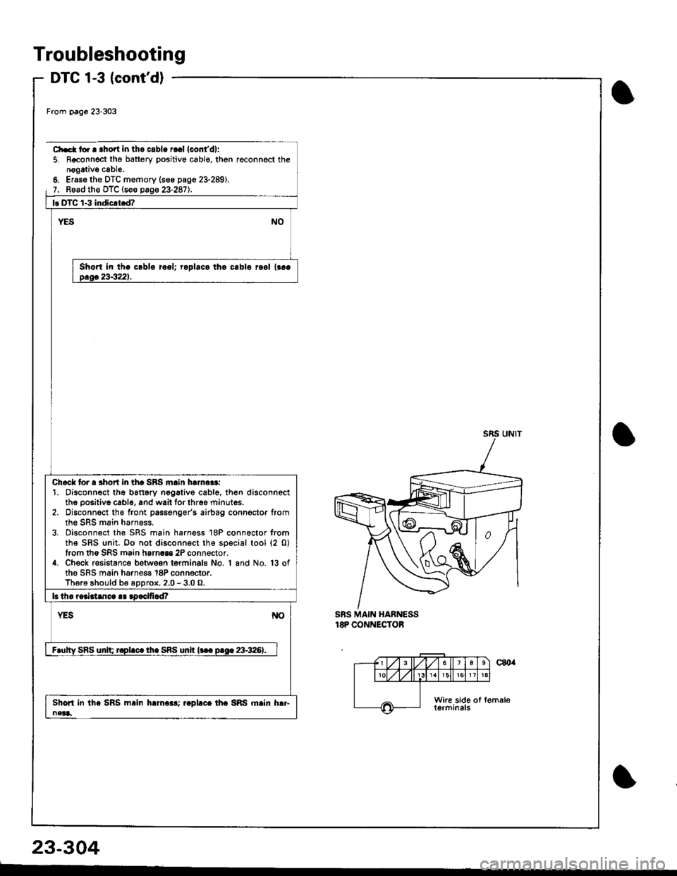
Chock tor a lhort in th. SRS m.in h.rn.$:1. 0isconnect ths batt6ry nogative cable, then disconnectthe positive cabl€, and wait forthres minutes.2. Disconnsct tho front passenger's airbag connoctor fromthe SRS main harn€ss,3. Disconnect the SRS main harness 18P connoctor fromthe SRS unit. Oo not disconnect the special tool (2 0)taom the SRS main harmaa 2P connector.4. Check resistance betwoon termin9ls No. 1 and No. 13ofthe SRS main harness 18P connector.Thero ghould be aDorox. 2.0- 3.0 o.
b tho roaidanca r! aDacifiod?
YESNO
F.utty SRS unlq r.pl.c.lh. SRS unir {... p.sE 23-3261.
Shon in the SRS m.in hamo$; r.Dl.c. th6 SRS rn.in h.r-neL.
From Dago 23-303
SRS MAIN HARNESS18P CONNECTOB
23-304
Page 1359 of 1681
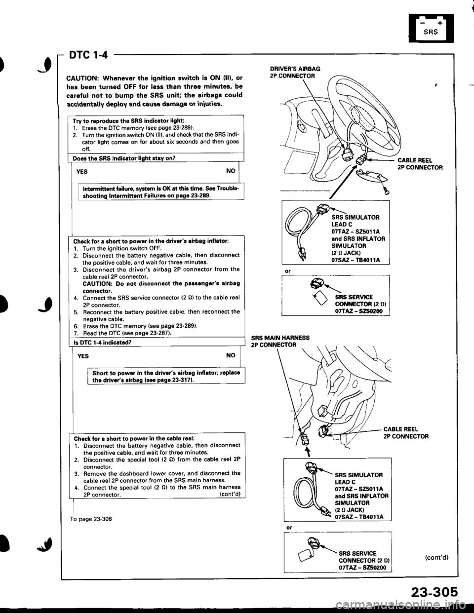
DTC 1-4
GAUTION: Whenever the ignition ewitch i! ON (ll), or
has been turned OFF tor l€ss than ihre€ minutes, be
caroful not to bump the SRS unit; tho airbag3 could
accidrnta[y deploy and caus€ damage or iniuries.
9--'-.- sns sERvrcE\,/ cli|f\FgfoR {2 ol07TAZ - SZqI200
ol
SRS SERVICEcot{ltEcToR {2 0}07TAZ - S:Zso2qt
CABLE REEL2P CONNECTOR
(cont'd)
Try to r.p.oduco tho SRS indicator light:1. Erase the DTC memory (see page 23-289).2. Turn the ignition switch ON (ll), and check that the SRS indi-
cator light comes on lor about six seconds and then goes
off.
Doo3tho SBS indic.tor light stry on?
YESNO
lnt rmittont tsiluio, systom i! (X tt thb timc. Soo Troublc
shooting Inte.mittani Failutca on P.g. 23-289.
Chock tor a shortto power in tha drivo/! ritbag inflllor:
l. Turn the ignition switch OFF.2. Disconnect the battery negativ€ cable, then disconnsct
th6 oositive cable, and wait for three minutes.
3. Disconn€ct the driver's airbtg 2P connector from the
cable reel 2P conn6ctor.CAUTION: Do not disconnost tha p!r3ong.t's rirbag
connoclor.4. Connect the SRS service connector (2 O) to the cable reel
2P connector,5. Reconnect the battery positive cable, then reconnect thenegative cabl€.6. Erase the DTC memory lsee page 23-289).7. Read the DTC (see gage 23-2aiL
|3 DTC 1-4 indicrtod?
YESNO
Shon to powa. in tha d val's tiabag itlflltor; iopl.cathe ddv.r'. airbag {t€c prge 23-317).
Check for ! short to pow.r in the cabls.oali1. Disconnect the battery negative cable. then disconnectthe positive cable, and wait for three minutes.2. Disconnect th€ special tool (2 o) from the cable reel 2P
conneclor.3. Remove the dashboard lower cover, and disconnect the
cable reel 2P connector from the SRS main harness./t. Connect the special tool (2 o) to tha SRS main harness
2P connector. (cont'd)
To page 23-306
)
,\fr)d
cffi
SRS SIMULATORLEAD C07TAZ - SZ5011Arnd SRS INFLATORSIMULATORt2 0 JACKI07SAz - TBil011A
23-305