cable HONDA INTEGRA 1998 4.G Owners Manual
[x] Cancel search | Manufacturer: HONDA, Model Year: 1998, Model line: INTEGRA, Model: HONDA INTEGRA 1998 4.GPages: 1681, PDF Size: 54.22 MB
Page 1309 of 1681
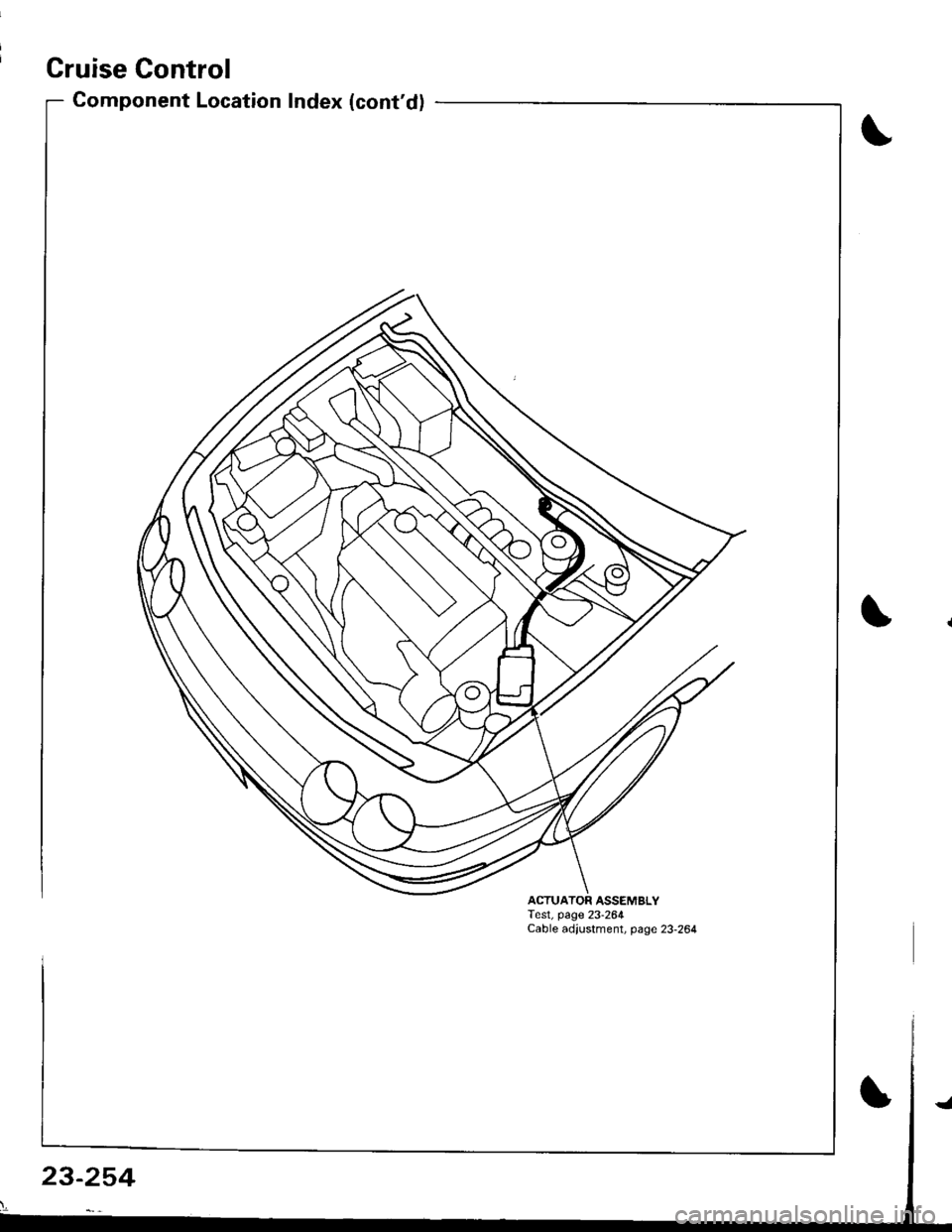
Cruise Control
Component Location Index (cont'd)
ACTUATOR ASSEMBLYTest, page 23-264Cable adjustment, page 23-264
23-254
Page 1310 of 1681
![HONDA INTEGRA 1998 4.G Owners Manual Circuit Diagram
J
WNT/BLK +WHT
BLKYEL YEL/8LU
CABLEREEL
SET/BESUME1 SW]TCH
J
IGNITONCONTROLMODULE(cM)
LT
B lA
i,"YlDGBY
c
IT GRN/RED LTGRN/BLK
BLK
I
:
:2013401
III
I
VEHICLE SPEEDSENSOR (VSS)
M/T: CL](/img/13/6069/w960_6069-1309.png "HONDA INTEGRA 1998 4.G Owners Manual Circuit Diagram
J
WNT/BLK +WHT
BLKYEL YEL/8LU
CABLEREEL
SET/BESUME1 SW]TCH
J
IGNITONCONTROLMODULE(cM)
LT
B lA
i,\"YlDGBY
c
IT GRN/RED LTGRN/BLK
BLK
I
:
:2013401
III
I
VEHICLE SPEEDSENSOR (VSS)
M/T: CL")
Circuit Diagram
J
WNT/BLK +WHT
BLKYEL YEL/8LU
CABLEREEL
SET/BESUME1 SW]TCH
J
IGNITONCONTROLMODULE(cM)
LT
B lA
i,"'YlDGBY
c
IT GRN/RED LTGRN/BLK
BLK
I
:
:2013401
III
I
VEHICLE SPEEDSENSOR (VSS)
M/T: CLLTCH SWITCH \A/T:A,TGEARPostT oN swrc!(oN E].tr tr
8LK 8LK
lltl-0-_L-- --
G301 G2AlG401
UNDER-HOOD FUSEiFELAY BOXUNDEF DASH FUSEi RELAY BOX
lNDICATORL]GHT(0.91W)
BLU/RED
23-255
:?:'
ACC : ACCELERATIONOEC iDECELERATION
Page 1313 of 1681
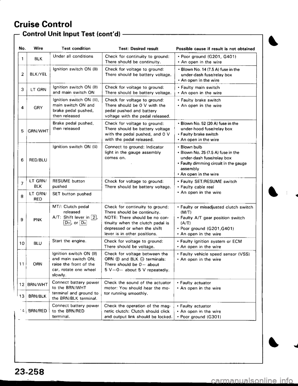
Cruise Control
- Control Unit InputTest(cont'dl
IBLKUnder all conditionsCheck for continuity to ground:
There should be continuity.
. Poor ground (G20l, G401). An open in the wire
2BLK/YEL
lgnition switch ON {ll}Check for voltage to ground:
There should be battery voltage.
. Blown No. l4 (7.5 Alfuse in the
under-dash fuse/relay box. An open in the wire
3LT GRNlgnition switch ON (ll)
and main switch ON
Check for voltage to ground:
There should be battery voltage.
. Faulty main swjtch. An open in the wire
GRY
lgnition switch ON (ll),
main switch ON and
brake pedal pushed,
then released
Check for voltage to ground:
There should be O V with the
pedal pushed and battery
voltage with the pedal released.
. Faulty brake switch. An open in the wire
5GRN/WHT
Brake pedal pushed,
then released
Check for voltage to ground:
There should be battery voltage
with the pedal pushed, and 0 V
with the pedal released.
Blown No. 52 (20 A)fuse in the
under-hood fuse/relay box
Faulty brake switch
An open in the wire
6RED/BLU
lgnition switch ON (ll)Connect to ground: lndicator
light in the gauge assembly
comes on.
Blown bulb
Blown No. 25 (7.5 A)fuse in the
under-dash fuse/relay box
Faulty dimming circuit in the gauge
assembly
An open in the wire
7LT GRN/
BLK
RESUME button
pushed
Check tor voltage to ground:
There should be battery voltage.
Faulty SET/RESUME switch
Faulty cable reel
An open in the wire8LT GRN/
RED
SET button pushed
IPNK
MT/: Clutch pedal
released
A/Tr Shift lever in [2l,
[Dl]. o, [o'l
-
Check for continuity to ground:
There should be continuity.
NOTE: There should be no con-
tinuity when the clutch pedal is
depressed or when the shift
lever is in other positions.
Faulty or misadjusted clutch switch(M/T)
Faulty A/T gear position switch(A/T)
Poor ground (G201,G401)
An open in the wire
't0BLUStart the engine.Check lor voltage to ground:
There should be voltage.
. Faulty ignition system or ECM. An open in the wire
't1ORN
lgnition switch ON (ll)
and main switch ON;
raase the front of the
car, rotate one wheel
slowly.
Check for voltage between the
ORN @ and BLK O terminals:
There should be 0- about
5 V-O- about 5 V repeatedly.
. Faulty vehicle speed sensor {VSS). An open in the wire
BRN/WHTConnect battery power
to the BRN/WHT
terminal and ground to
the BRN/BLK terminal.
Check the sound of the actuator
motor: You should hear the mo-
tor running smoothly.
. Faulty actuator. An open in the wire
BRNi BLK
Connect battery power
to the BRN/RED
Iermrnal.
Check the operation of the mag-
netic clutch: Clutch should click
and output link should be locked.
Faulty actuator
An open in the wire
Poor ground (G30'l)
No. Wire Test conditionTest: Desiled result Possible cause il lesult is not obtained
' 4 I BRN/RED
{
{
23-258
-L
Page 1314 of 1681
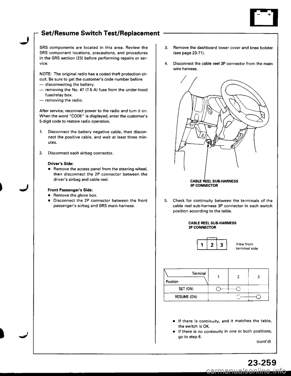
Set/Resume Switch Test/Replacement
SRS comDonents are located in this area. Review the
SRS component locations, precautions, and procedures
in the SRS section (23) before performing repairs or ser-
vice.
NOTE: The original radio has a coded theft protection cir-
cuit, Be sure to get the customer's code number before- disconnecting the battery.- removing the No. 47 {7.5 A} fuse from the under-hood
fuse/relav box.- removing the radio.
Atter service, reconnect Dower to the radio and turn it on.
When the word "CODE" is displayed, enter the customer's
s-digit code to restore radio operatior..
1. Disconnect the battery negative cable, then discon-
nect the oositive cable, and wait at least three min-
utes,
2. Disconnect each airbag connector.
Drivor's Side:
a Remove the access panel from the steering wheel,
then disconnect the 2P connector between the
driver's airbag and cable reel,
Front Passenge;'s Side:
a Remove the glove box.
. Disconnect the 2P connector between the front
passenger's airbag and SRS main harness.
)
Remove the dashboard lower cover and knee bolster(see page 23-71).
Disconnect the cable reel 3P connector trom the main
wire harness.
CABLE REEL SU&HARNESS3P CONNECTOR
Check for continuiw between the terminals of the
cable reel sub-harness 3P connector in each switch
position according to the table.
CAALE REEL SUB.HARNESS3P CONNECTOR
terminalside
lf there is continuity, and it matches the table,
the switch is OK.
lf there is no continuity in one or both positions,
go to step 6.(cont'd)
Terminal
t"*-
---\23
SET {ON)oC
RESUME (ON}o
23-259
Page 1315 of 1681
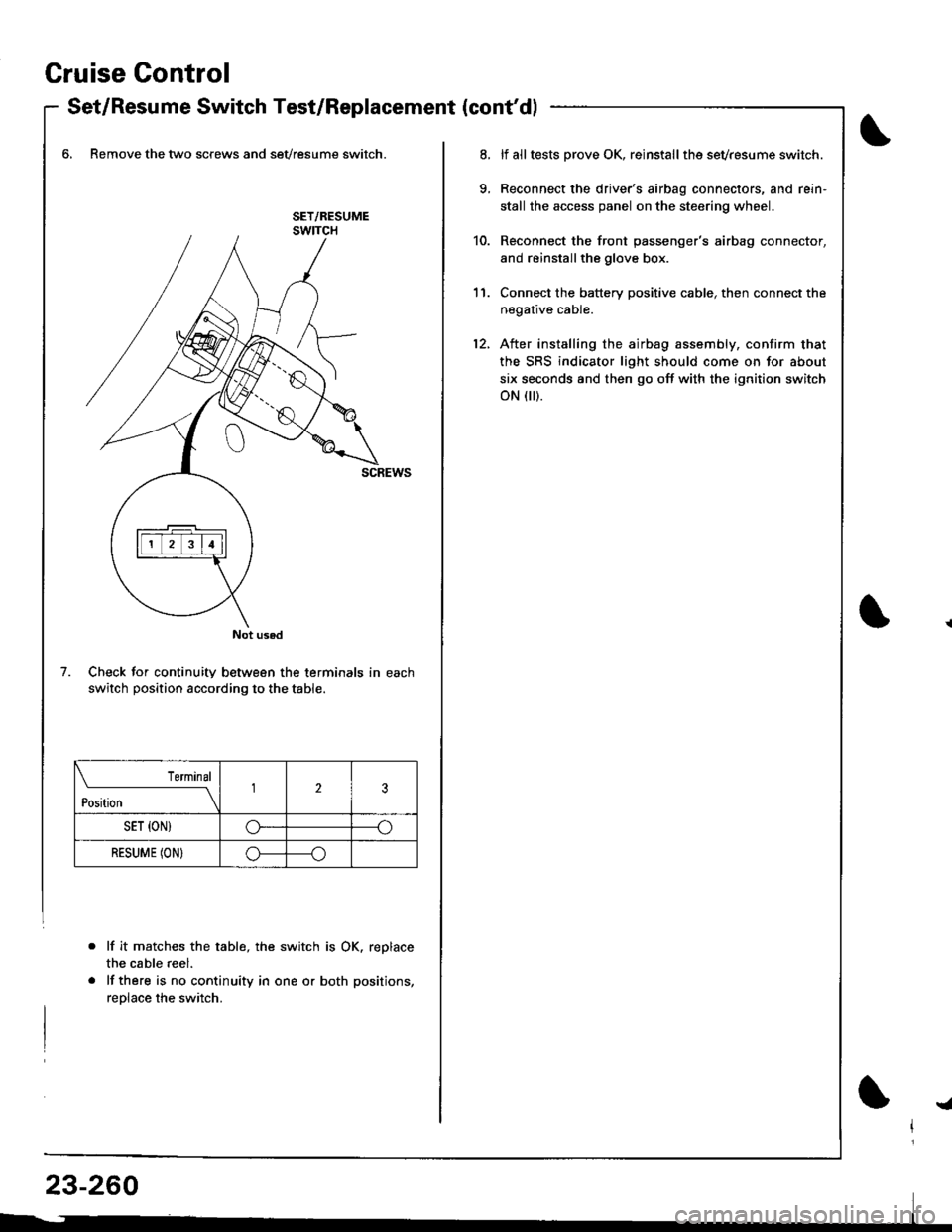
Gruise Control
- Set/Resume Switch Test/Replacement {cont'dl
6, Remove the two screws and sevresume switch.
Check for continuity between the terminals in each
switch position according to the table.
lf it matche$ the table, the switch is OK. replace
the cable reel.
lf there is no continuity in one or both positions,
reolace the switch.
Not used
7.
Terminal
t*n*------l23
SET {ON)G----o
RESUME (ON}o----o
lf alltests prove OK, reinstallthe sevresume switch.
Reconnect the driver's airbag connectors, and rein'
stall the access panel on the steering wheel.
Reconnect the front passenger's airbag connector,
and reinstallthe glove box.
Connect the battery positive cable, then connect the
negative cable.
After installing the airbag assembly, confirm that
the SRS indicator light should come on for about
six seconds and then go off with the ignition switch
oN flr).
11.
12.
!a
Page 1319 of 1681
Cruise Gontrol
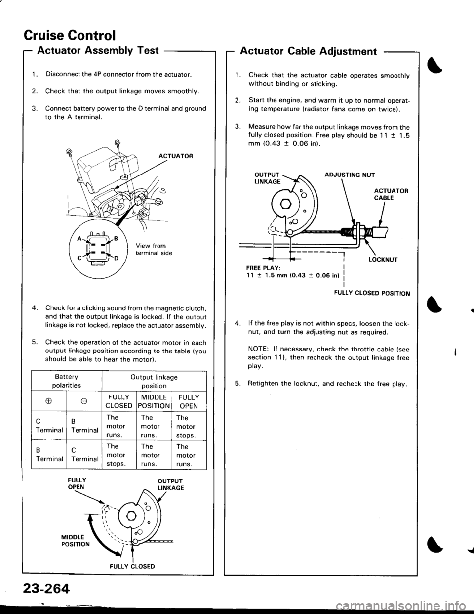
1.
Actuatol Assembly Test
Disconnect the 4P connector from the actuator.
Check that the output linkage moves smoothly.
Connect battery power to the D terminal and ground
to the A terminal.
ACTUATOR
Check tor a clicking sound from the magnetic clutch.
and that the output linkage is locked. lf the outputlinkage is not locked, replace the actuator assembly.
Check the operation of the actuator moror In eacn
output linkage position according to the table (you
should be able to hear the motor).
FULLY CLOS€D
2.
3.
3.
23-264
Actuator Cable Adjustment
Check that the actuator cable operates smoothly
without binding or sticking.
Start the engine, and warm it up to normal operat-
ing temperature (radiator fans come on twice).
Measure how far the output linkage moves from thefully closed position. Free play should be 11 t 1,5mm (0.43 t 0.06 in).
FREE PLAY:1M.5 mm (0.43 1 0.06 in)
FULLY CLOSED POSITTON
4. lf the free play is not within specs, loosen the lock-
nut, and turn the adjusting nut as required.
NOTE: It necessary, check the throttle cable (see
section 1 1), then recheck the output linkage lreeplay.
5. Retighten the locknut, and recheck the free play.
^ffi"
c17i l,io
Battery
polaritiesOutput linkage
position
ooFULLY
CLOSED
MIDDLE
POSITION
FULLY
OPEN
c
Terminal
B
Terminal
The
moror
runs.
The
molor
runs.
The
motor
stops.
B
Terminal
c
Terminal
The
motor
stops.
The
motor
runs.
The
motor
runs.
{
Page 1331 of 1681
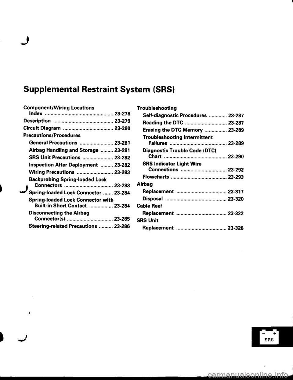
Supplemental Restraint System (SRSI
Component/Wiring Locations
fndex ................ ......23-218
Description ................23-279
Circuit Diagram .........23-280
Precautions/Procedures
General Precautions ........................ 23-281
Airbag Handling and Storage .........23-281
SRS Unit Precautions ...................... 23-28P
f nspection After Deployment ......... 23-282
Wiring Precautions .......................... 23-283
Backprobing Spring-loaded Lock
Troubleshooting
Seff-diagnostic Procedures ............. 23-287
Reading the DTC .................. ...........- 23-287
Erasing the DTC Memory ................ 23-289
Troubleshooting Intermittent
Failures .............. 23-289
Diagnostic Trouble Code (DTC)
Chart ................ ..23-290
SRS Indicator Light Wire
Connestions ...... 23-252
Ff owcharts .............23-293
Ailbag
Repf acement ......... 23-317
Disposaf .................23-320
Cable Reel
Replacement .........23-322
SRS Unit
Replacement .........23-326
1 Connectors ........23-28:t
.r/ Spring-foaded Lock Connector ....... 23-284
Spring-loaded Lock Connestor with
Buift-in Short Contact .............. ... 23-281
Disconnecting the Airbag
Connector(sl ......23-285
Steering-related Precautions .......... 23-286
)f-'Tl
Page 1332 of 1681
!
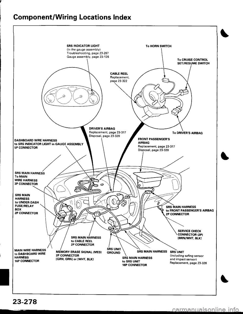
Gomponent/Wiring Locations Index
SRS INDICATOR LIGHT(ln the gauge assembly)Troubleshooting, page 23-287Gauge assembly, page 23-126
To HORN SWITCH
CABLE REELReplacement,page 23-322
DRIVER'S AIRBAGReplacement. page 23-317Disposal, page 23-320To DRIVER'S AIRBAG
DASHBOARD WIRE HARNESSFRONT PASSENGER'SAIRBAGBeplacement, page 23-317Disposal, page 23-320
to SRS INDICATOR LIGHT in GAUGE ASSEMBLY5P CONNECTOR
SRS MAIN HARNESSTo MAINWIRE HARNESS3P CONNECTOR
SRS MAINHARNESSto UNDER-DASHFUSE/RELAYBOX2P CONNECTOR
HARNESSto FRONT PASSENGERS AIRBAG2P CONNECTOR
SRS MAIN
SERVICE CHECXCONNECTOR {2PIIBRNAAIHT, BLK]to CABLE REEL2P CONNECTOR
MAIN WIRE HARNESSto DASHBOARD WIREHARNESS16P CONNECTOR
ERASE SIGNAL (MES}SRS UNITGBOUNOSRS MAIN HARNESSSRS UNIT(lncluding safing sensorano rmpact sensor)R6placement, page 23-326
2P CONNECTORSRS MAIN HARNESSto SRS UNIT18P CONNECTOR
S\--0
[GRN, GRNI or IWHT, BLKI
23-27A
Page 1333 of 1681

)
\ \, ili \.-.-1 i^\\,,; i \
The SRS is a safetv device which, when used in coniunction with the seat belt, is designed to help protect the driver and
front passenger in a frontal")
Description
I
J)
)
'\' '\, ili \.-.-1 i^\\,,; i \
The SRS is a safetv device which, when used in coniunction with the seat belt, is designed to help protect the driver and
front passenger in a frontal impact exceeding a cenain set limit. The system consists ot the SRS unit (including safing sen-
sor and imDact sensor), the cable reel, the driver's airbag, and front passenger's airbag
Operation t'Its
The main circuit in the SRS unit senses and judges the force ot impact and, il necessary, ignites the inflator charges. If bat-
tery voltage is too low or power is disconnected due to the impact, the back-up power circuii will keep voltage at a con-
stant level.
For the SRS to operate:
(1) The impact sensor and safing sensor must activate and send electric signals to lhe mictop.Goi
{2) The microprocessor must compute the signals and send signals to the airbag inflators'
(3) The inflators must ignite and deploy the airbags sE Lr.r
UNDER DASHFUSE/RELAYBOX
Dnftr sAtacranroq
IIMPACT I ] )
F80t{TPASSEI{GEffSAIRSAGINFLAIOR
Drc MES SCS rDC
Self-diagnosis System
A self-diagnosis circuit is built into the sRs unit; when the ignition switch is turned oN (ll), the sRS indicator light comes
on and goes off after about six seconds if the system is operating normally'
lf the light does not come on, or does not go off after six seconds, or if it comes on while driving. it indicates an abnormal-
ity in the system. The system must be inspected and repaired as soon as possible'
For better servicesbility. the memory will store the cause of the malfunction, and the data link circuit passes on the infor-
mation from the memory to the data link connector (DLC). This information can be read with the Honda PGM Tester con-
nected to the DLc (16P).
23-279
J
Page 1335 of 1681
)
Precautions/Procedures
General Precautions
Carefully inspect any SRS part before you install it,
Do not install any part that shows signs of being drop-
ped or improperly handled. such as dents, cracks or
deformstion:
- Airbags- Cable reel- SRS unit
' Use only a digital multimeter to check the system lf
it's not a Honda multimeter. make sure its output is
10 mA (0.01 A) or less when switched to the smallest
value in the ohmmeter range. A tester with a higher
output could damage the airbag circuit or cause acci-
dental deployment and possible injury.
r Do not install used SRS parts from anothercar.When
making SRS repairs, use only new parts.
r Except when performing electrical inspections,
always disconnect both the negative cable and posl-
tive cable from the batterY, and wait at least three
minutes before beginning work.
r Replacement of the combination light and wiper/
washer switches and cruise control switch can be
done without removing the steering wheel:
- Combination light and wiperlwasher switch replace-
ment (see page 23-268).- Cruise controi sevresume switch replacement (see
page 23-259t.
. Whenever the ignition switch is ON (ll), or has been
turned OFF for less than three minutes, be caretul not
to bump the SRS unit; the airbags could accidentally
deploy and cause damage or iniuries.
. Whenever the airbag has been activated, replace the
SRS unit.
. The original radio has a coded theft protection circuit.
Be sure to get the customer's code number beJore dis-
connecting the battery cables.
23-281
Airbag Handling and Storage
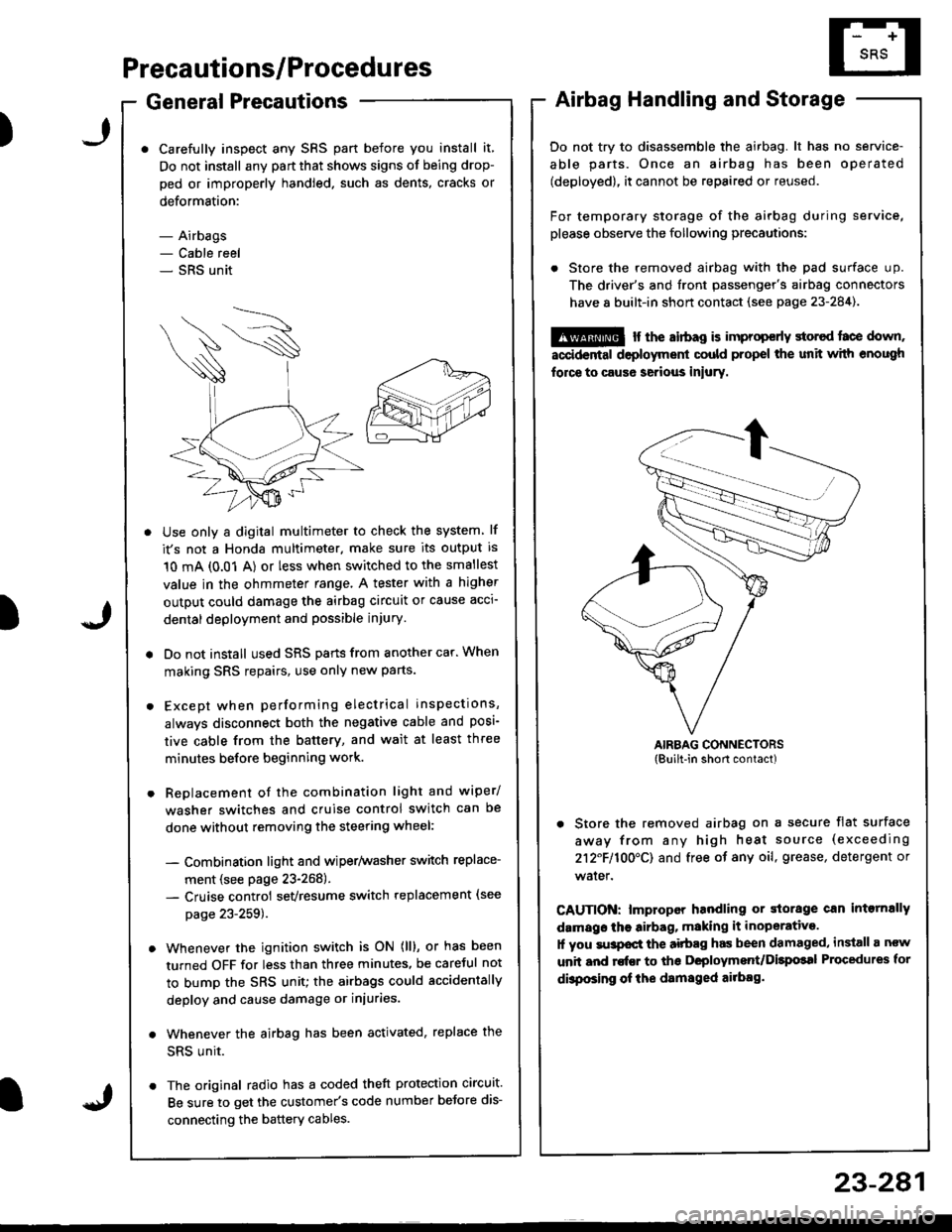
Do not try to disassemble the airbag. lt has no service-
able parts. Once an airbag has been operated
(deployed), it cannot be repaired or reused.
For temporary storage of the airbag during service,
please observe the following precautions:
. Store the removed airbag with the pad surface up.
The driver's and tront passenger's airbag connectors
have 8 built-in short contact (see page 23-284).
@ r the airbag is improp€rly storcd face down,
accidental deployment could propel the unit with enough
force to caus6 serious iniury.
AIRBAG CONNECTORS(Built-in short contact)
. Store the removed airbag on a secure flat surface
away from any high heat source (exceeding
212F110O'CI and free of any oil, grease, detergent or
water.
CAUTION: lmproper handling or storage can intornally
damags the airbag, making it inoperative.
1l you su3pocl the aitbag has been damaged, install a ncw
unit and rofEr to ths Deployment/Dilpolal Procedures for
dbposing of ihe damsged ailbag.
)