cable HONDA INTEGRA 1998 4.G Manual Online
[x] Cancel search | Manufacturer: HONDA, Model Year: 1998, Model line: INTEGRA, Model: HONDA INTEGRA 1998 4.GPages: 1681, PDF Size: 54.22 MB
Page 1138 of 1681
I
,.
u
J
/
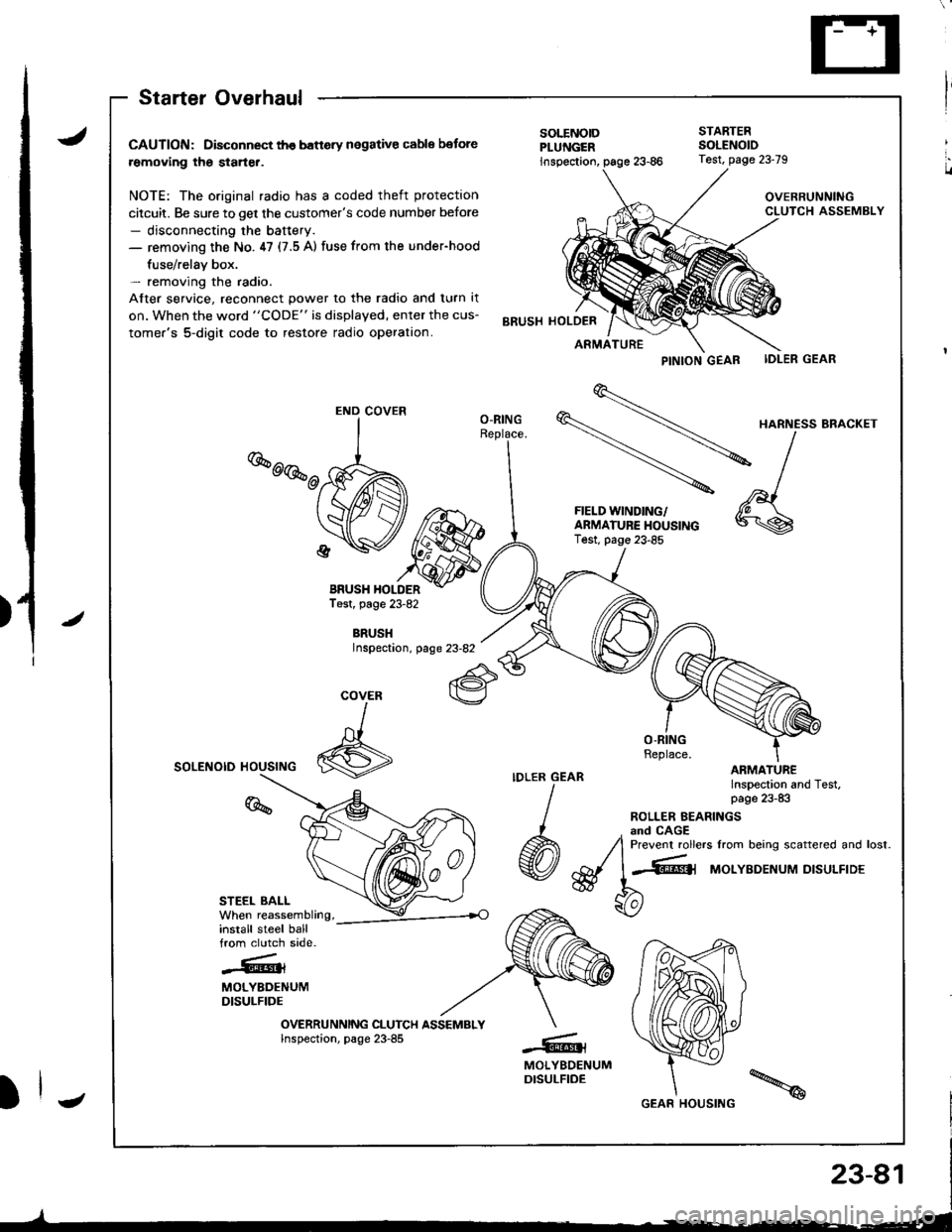
Starter Overhaul
CAUTION: Disconnect th€ banery negative cable botore
removing the starter.
NOTE: The original radio has a coded theft protection
citcuit. Be sure to get the customer's code number before- disconnecting the baftery.- removing the No. ,17 (7.5 A) fuse from the under-hood
fuse/relav box.- removing the radio.
After service, reconnect power to the radio and turn it
on. When the word "CODE" is displayed, enter the cus-
tomer's 5-digit code to restore radio operation.
BRUSH HOLDERTest, page 23-82
BRUSHInspectaon, page 23-82
SOLENOID HOUSING
STEEL BALL
install steel ballfrom clutch side.
-.''.!k.rt{l{
MOLYBDENUMDISULFIDE
OVERRUNNING CLUTCH ASSEMBLYInspection, page 23-85
PINTON GEAB IDLER GEAR
\
HARNE'SBRA.KET
-\l
-
^,1FIELD WINDING/ 'A \
f:$i:y5J*"""
*\s
SOLENOIDPLUNGER
STARTEBSOLENOID
inspection,
BRUSH HOLDER
Test, page 23-79
OVERRUNNINGCLUTCH ASSEMBLY
ARMATURE
O-RING
COVER
I
6
%
-@t
MOLYBDENUMDISULFIDE
END COVER
GEAR HOUSING
Page 1144 of 1681
J
Starting System
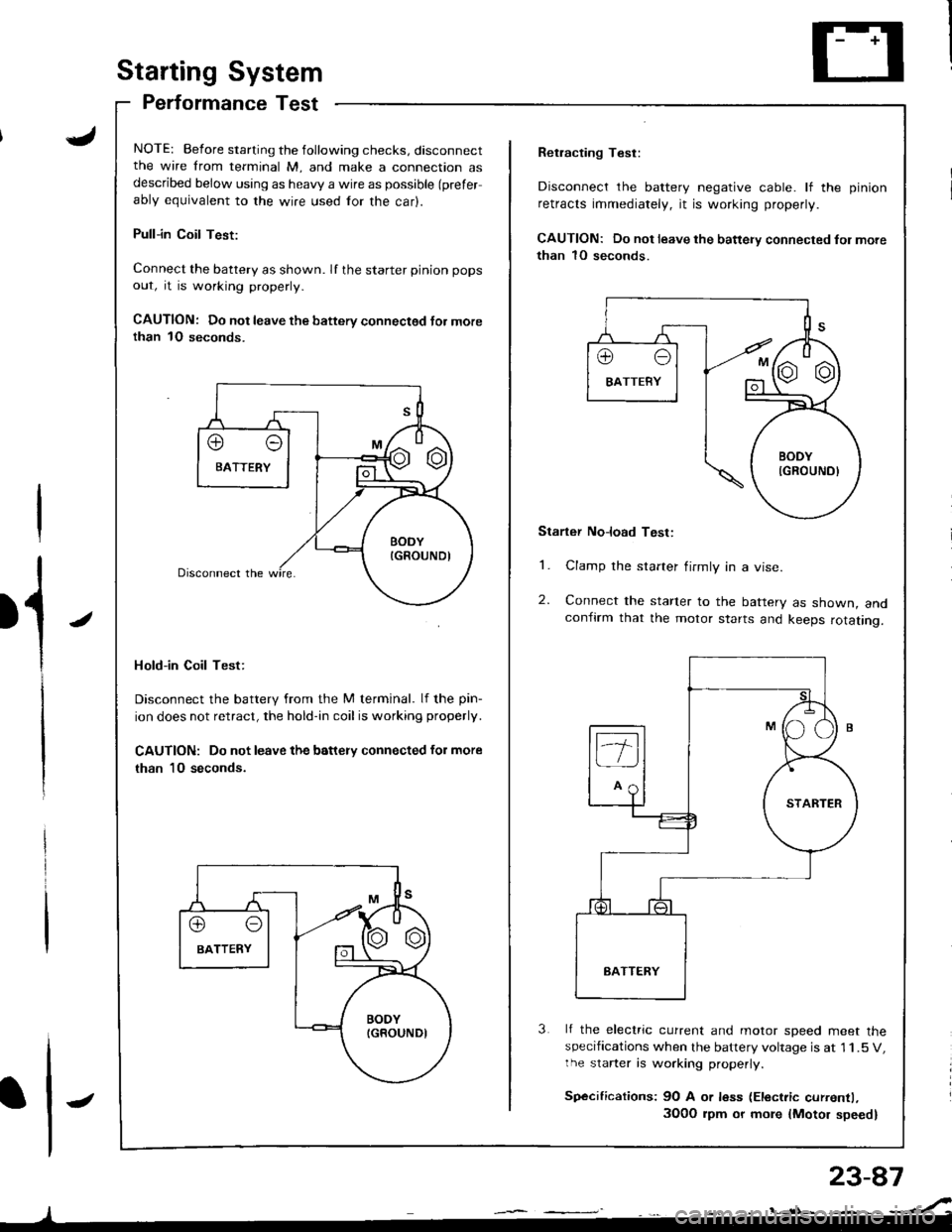
Performance Test
NOTE: Before starting the following checks, disconnectthe wire from terminal M, and make a connection asdescribed below using as heavy a wire as possible (prefer
ably equivalent to the wire used for the car).
Pull-in Coil Test:
Connect the battery as shown. If the starter pinion pops
out, it is working properly.
CAUTION: Do not leave the battery connectsd Jor morethan 1O seconds.
Hold-in Coil Test:
Disconnect the battery from the M terminal. lf the pin-
ion does not retract, the hold-in coil is working properly.
CAUTION: Do not leave the battery connected for more
than 10 seconds.
J
Retracting Test:
Disconnect the battery negative cable. lf the pinion
retracts immediately, it is working properly.
CAUTION: Do not leave the battery connected fol more
than 1O seconds.
Starter No]oad Test:
1. Clamp the starter firmly in a vise.
2. Connect the starter to the battery as shown, andconfirm that the motor starts and keeps rotating.
3 lf the electric current and motor soeed meet thespecifications when the battery voltage is at 1 1.5 V,the starter is working properly.
Sp€cifications: 9O A or less (Electric currentl,
3O0O rpm or more {Motor speed}
Page 1162 of 1681
{
t
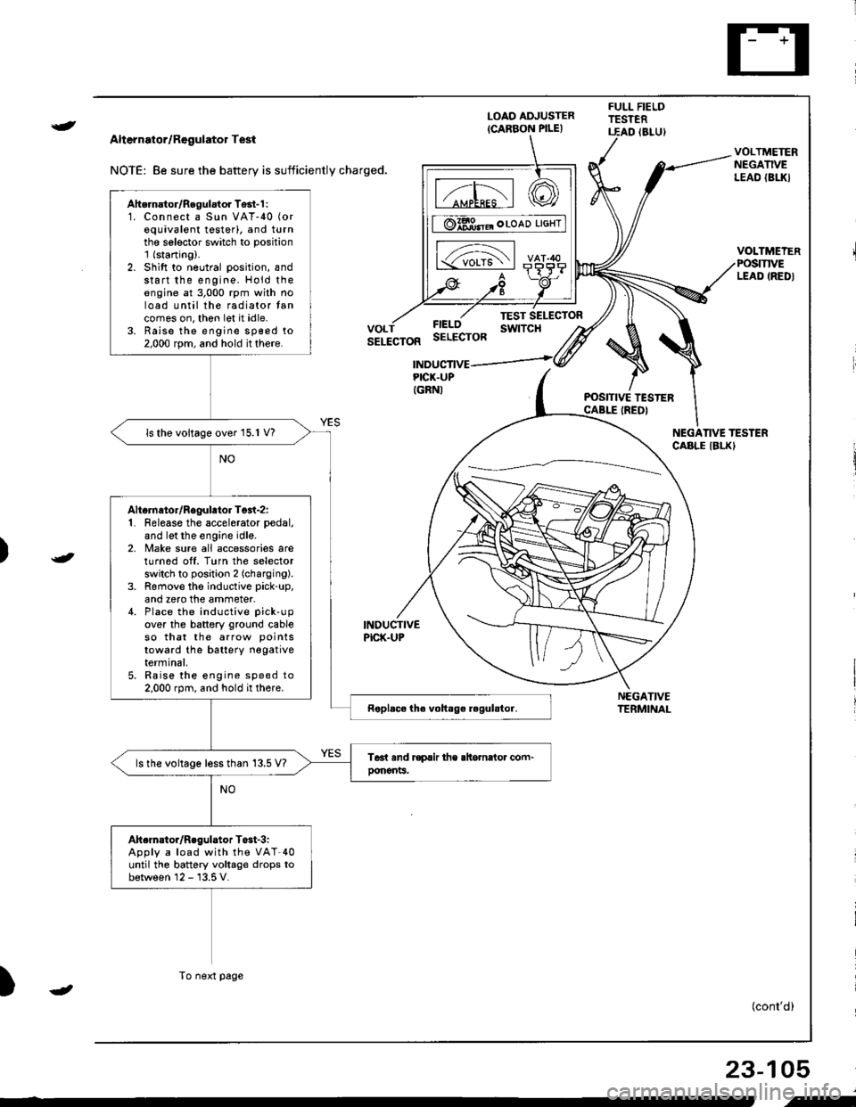
Alternator/Regulator Test
NOTE: 8e sure the battery is sufficiently charged.
LOAO ADJUSTER
ICARBON PILE)
FULL FIELDTESTERT.EAD (8LU)
POSITIVE TESTERCABLE IREDI
NEGATIVETERMINAL
VOLTMETERNEGATIVELEAO {BL|(}
VOLTMEIERPOSmVELEAD IREDI
FIELOSELECTOR
TEST SELECTORswtTcHVOLTSELECTOR
INDUCTIVEPICK.UP
INDUCTIVEPICK.UPIGRNI
NEGANVE TESTERCABLE IBLKI
)
)
{cont'd)
23-105
Ahernator/Regulator Tosl-1 :1. Connect a Sun VAT-40 (or
equivalent testerl, and turnthe selector switch to position'1 (starting).
2. Shift to neutral position, andstart the engine. Hold theengine at 3,000 rpm with noload until the radiator tancomes on, thon let it idle.3. Raise the engine sp€ed to2,000 rpm, and hold it there.
ls the voltage over 15.1 V?
Altsrnator/Rogulator Test-z:1. Release the accelerator pedal,
and let the engine idle.2, Make sure all accessories areturnod off. Turn the selectorswitch to position 2 (charging).
3. Remove the inductive pick-up,
and zero the ammeter.4. Place the inductive pick-up
over the battery ground cableso that the arrow points
toward the batterY negativeterminal,5. Raise the engine speed to2.000 rpm, and hold it there.
ls the voltage less than 13.5 V?
Ahelnstor/Regulator T$t-3iApply a load with the VAT-40until the battery voltage drops tobetween 12 - 13.5 V.
To next page
-
i-
Page 1164 of 1681
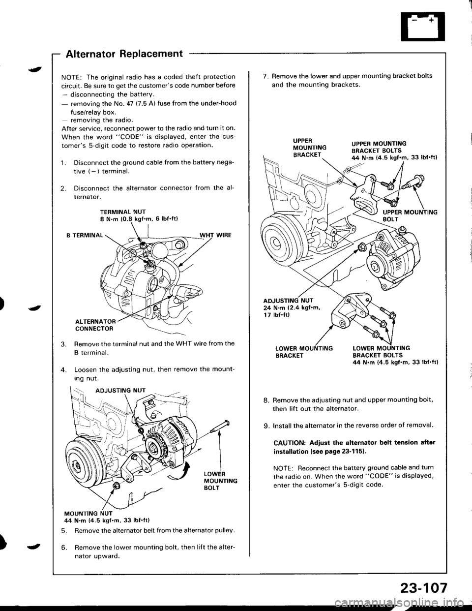
Alternator Replacement
)
t
-
NOTE: The original radio has a coded theft protection
circuit. Be sure to get the customer's code number before
- disconnecting the battery.
- removing the No. 47 (7.5 A) fuse from the under-hood
fuse/relay box.
removing the radio.
After service, reconnect power to the radio and turn it on.
When the word "CODE" is displayed, enter the cus
tomer's s-digit code to restore radio operation.
1. Disconnect the ground cable from the battery nega-
tive (- ) terminal.
2. Disconnect the alternator connector from the al-
lernalor,
TERMINAL NUT8 N,m (O.8 kgf'm, 6 lbl'ft)
B TERMINAL
ALTERNATORCONNECTOR
Remove the terminal nut and the WHT wire from the
B terminal.
Loosen the adjusting nut, then remove the mount-
Ing nut.
MOUNTINGBOLT
MOUNTING NUT44 N.m (4.5 kgf.m.33 lbt.ftl
5. Remove the alternator belt from the alternator pulley.
6. Remove the lower mounting bolt, then lilt the alter-
naror upwaro.
3.
{--,
7.Remove the lower and upper mounting bracket bolts
and the mounting brackets.
BRACKET BOLTSil4 N.m {4.5 kgl.m, 33 lbt.ft)
8. Remove the adiusting nut and upper mounting bolt,
then lift out the alternator.
9. lnstallthe alternator in the reverse order of removal.
CAUTION: Adiust the alternator belt tension aftsr
installation lseo page 23-1151.
NOTE: Reconnect the battery ground cable and turn
the radio on. When the word "CODE" is displayed,
enter the customer's s-digit code.
BRACKET
UPPER MOUNTINGBRACKET EOLTS44 N.m {4.5 kgl.m, 33 lbl'ft)
24 N.m (2.4 kgf.m,17 rbf.ftl
b-h..K
) I
23-107
-
,-
Page 1243 of 1681
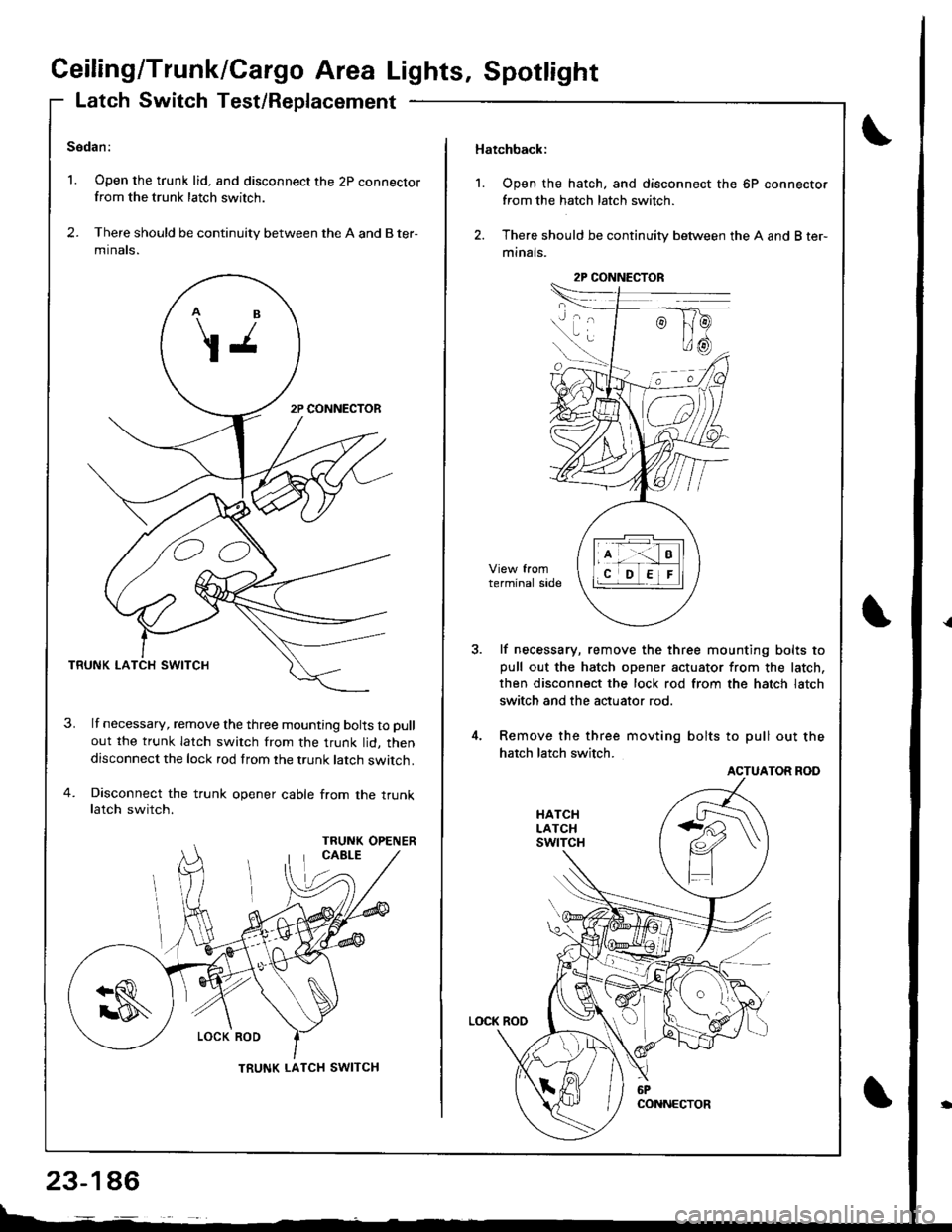
Ceiling/Trunk/Cargo Area Lights, Spotlight
Latch Switch Test/Replacement
Sedan:
1. Open the trunk lid. and disconnect the 2p connectorfrom the trunk latch switch.
2. There should be continuity between the A and B ter-
mtnats.
TRUNK LA
lf necessary, remove the three mounting bolts to pull
out the trunk latch switch from the trunk lid, thendisconnect the lock rod from the trunk latch switch.
Disconnect the trunk opener cable from the truoklatch switch.
OO
TRUNK LATCH SWITCH
23-146
Hatchback:
1. Open the hatch, and disconnect the 6P connector
from the hatch latch switch.
2. There should be continuity between the A and B ter-
minals.
lf necessary, remove the three mounting bolts topull out the hatch opener actuator from the latch,
then disconnect the lock rod from the hatch latch
switch and the actuator rod.
Remove the three movting bolts to pull out the
hatch latch switch.
ACTUATOR ROD
2P CONNECTOR
Page 1260 of 1681
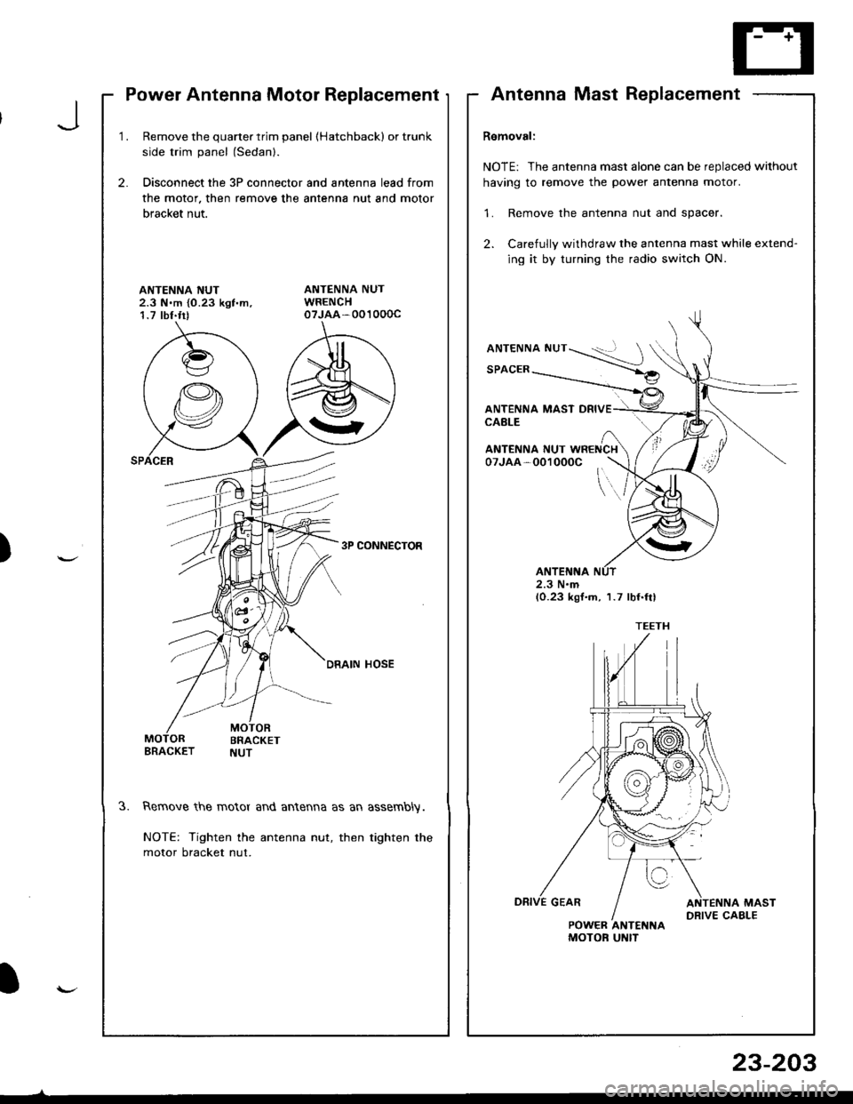
Power Antenna Motor Replacement
1.Remove the quarter trim panel (Hatchbackl or trunk
side trim panel (Sedanl.
Disconnect the 3P connector and antenna lead from
the motor. then remove the antenna nut and motor
bracket nut.
2.
ANTENNA NUT2.3 N.m {0.23 kgf'm,1.7 tbf.trt
3P CONNECTOR
DRAIN HOSE
3.Remove the motor and antenna as an assembly.
NOTE: Tighten the antenna nut, then tighten the
motor bracket nut.
AntennaMastReplacement
Removal:
NOTE: The antenna mast alone can be replaced without
having to remove the power antenna motor.
1. Remove the antenna nut and spacer.
2. Carefully withdraw the antenna mast while extend-
ing it by turning the radio switch ON.
ANTENNA NUT
SPACER
ANTENNA MAST DRIVECABLE
\..
ANTENNA NUT WRENCH07JAA-001000C
2.3 N.m(0.23 kgf.m, 1.7 lbf.ftl
POWER ANTENNAMOTOF UNIT
J
)
I
23-203
Page 1261 of 1681
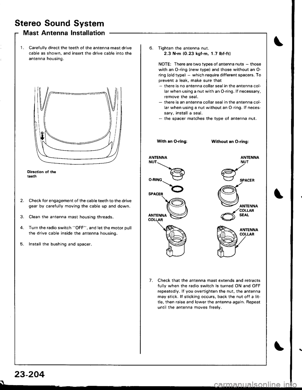
Stereo Sound System
Mast Antenna Installation
Carelully direct the teeth of the antenna mast drive
cable as shown, and insert the drive cable into the
antenna housino.
Diroction ol th6teeth
Check for engagement of the cable teeth to the drive
gear by caretully moving the cable up and down.
Clean the antenna mast housing threads.
Turn the radio switch "OFF", and let the motor pull
the drive cable inside the antenna housing.
Install the bushing and spacer.
23-204
s
6. Tighten the antenna nut.
2.3 N.m (0.23 kgf .m. 1.7 lbf.ftl
NOTE: There are two types of antenna nuts - those
with an O-ring (new type) and those without an O-
ring (old type) - which require different space.s. To
prevent a leak, make sure that- there is no antenna collar seal in the antenna col-
lar when using a nut with an O-ring. lf necessary,
remove the seal.- there is an antenna collar sealin the antenna col-
lar when using a nut without an O-ring. It neces-
sary, install a seal.- the spacer matches the type of antenna nut.
With an O-ring:
ANTENNANUT__.\
a€^1.i*-lr
O-RING
Without an O-ring:
ANTENNA
ANTENNANUT
6d{.i*-.-r
SPACER
(Q\
Vorr.""o
_/coLrjlR
6 t'o'-
Check that the antenna mast extends and retracts
fully when the radio switch is turned ON and OFF
repeatedly. ll you overtighten the nut, the antenna
may stick. lf sticking occurs. back the nut of{ a lit-
tle, then raise and lower the antenna again. Repeat
until the antenna moves freely.
7.
Page 1264 of 1681
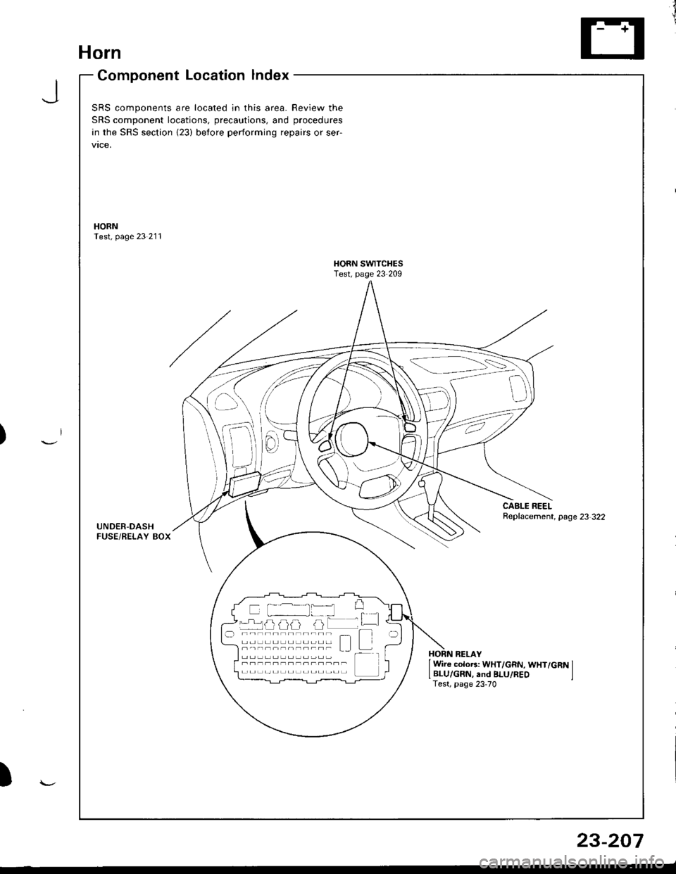
Horn
Component Location lndex
JSRS components are located in this area. Review the
SRS component locations, precautions, and procedures
in the SRS section {23) before performing repairs or ser-
vtce,
HORNTest, page 23 211
HORN SWITCHESTest, page 23-209
CABLE REELReplacement, page 23 322UNDER-DASHFUSE/BELAY BOX
{---=-\s":=',-i=
il
-rrj _LJLi lJJJ I -.r ----------;- - t--t -----,------- L I t---HORN RELAY
I Wire colo6: WHT/GRN, WHT/GRN ILBLU/GRN, and BLU/REO ITest, page 23-70
)
23-207
Page 1266 of 1681
SwitchTest
SRS comDonents are located in this area. Review the
SRS component locations, precautions, and procedures
in the SRS section (23) before performing repairs or ser-
vtce.
NOTE: The original radio has a coded thett protection cir-
cuit. Be sure to get the customer's code number beJore- disconnecting the battery.- removing the No. 47 (7.5 A) fuse from the under-hood
fuse/relay box.- removing the radio.
After service, reconnect Dower to the radio and turn it on.
When the word "CODE" is displayed, enter the customer's
5-digit code to restore radio operation
Disconnect the battery negative cable, then discon-
nect the positive cable, and wait at least three min-
uIes.
Disconnect each airbag connector.
Driver's Side:
a Remove the access panel from the steering wheel,
then disconnect the 2P connector between the
driver's airbag and cable reel.
Front Passenger's Side:
. Remove the glove box,
a Disconnect the 2P connector between the front
passenger's airbag and SRS main harness.
1.
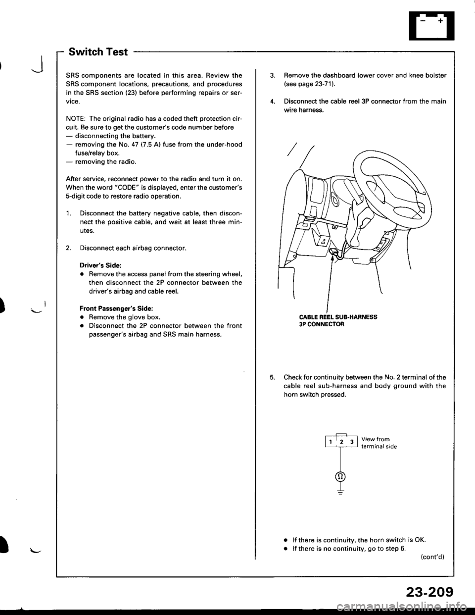
Remove the dashboard lower cover and knee bolster(see page 23-71).
Disconnect the cable reel 3P conneclor from the main
wtre narness.
CABLE REEL SUB.HARNESS3P CONNECTOR
Check for continuitv between the No. 2 terminal of the
cable reel sub-harness and body ground with the
horn switch Dressed.
terminalside
a
It there is continuity, the horn switch is OK.
lf there is no continuity, go to step 6. (cont,d)
r-P r11 2 3l-t-
I
I\-J
)
I
23-209
Page 1267 of 1681
Horn
Switch Test (cont'd)
Remove the driver's airbag assembly (refer to the
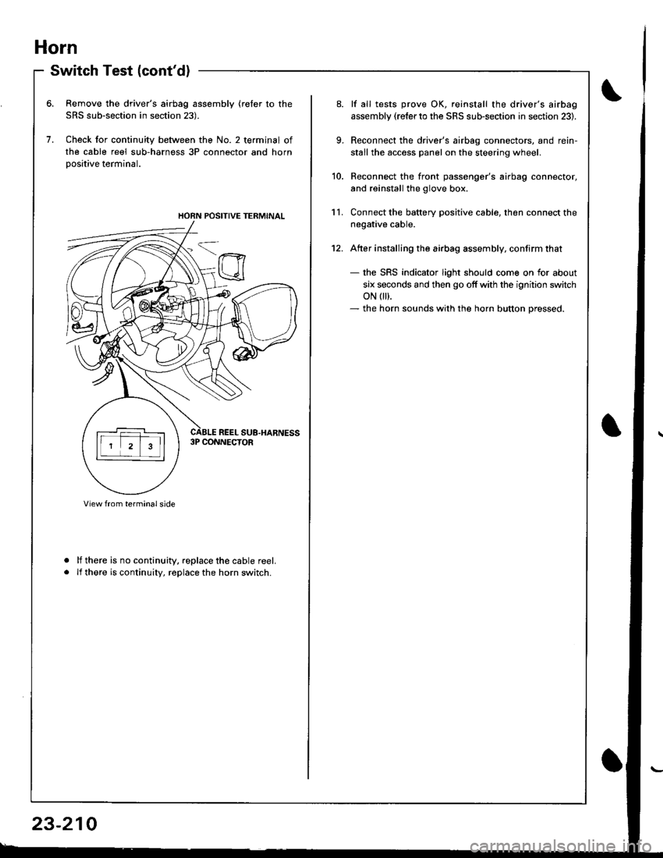
SRS sub-section in section 23).
Check for continuity between the No. 2 terminal of
the cable reel sub-harness 3P connector and horn
Dositive terminal.
lf there is no continuity. replace the cable reel.
lf there is continuity, replace the horn switch.
a
a
HORN POSITIVE TERMINAL
23-210
9.
10.
11.
12.
lf all tests prove OK, reinstall the driver's airbag
assembly (re{er to the SRS sub-section in section 23).
Reconnect the driver's airbag connectors, and rein-
stall the access panel on the steering wheel.
Reconnect the front passenger's airbag connector,
and reinstall the glove box.
Connect the battery positive cable, then connect the
negative cable.
Atter installing the airbag assembly, confirm that
- the SRS indicator light should come on for about
six seconds and then go off with the ignition switch
oN 0t).- the horn sounds with the horn button pressed.