service HONDA INTEGRA 1998 4.G Workshop Manual
[x] Cancel search | Manufacturer: HONDA, Model Year: 1998, Model line: INTEGRA, Model: HONDA INTEGRA 1998 4.GPages: 1681, PDF Size: 54.22 MB
Page 1139 of 1681
Staning System
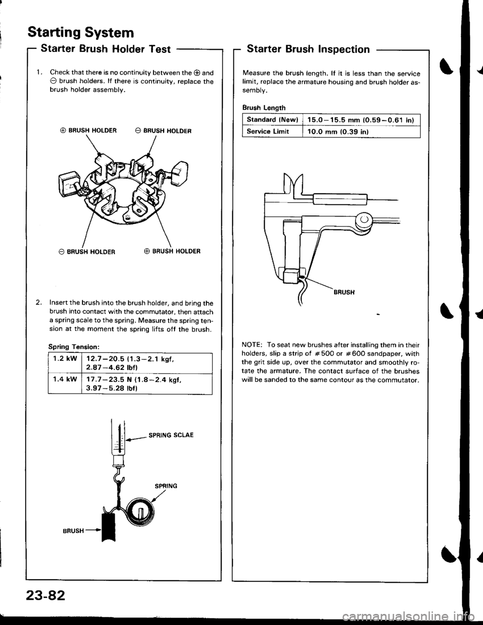
Starter Brush Holder TestStarterInspection
Measure the brush length. lf it is less than the servicelimit, replace the armature housing and brush holder as-
semoty.
Brush Length
Standard lNew)15.o- 15.5 mm (O.59-0.61 inl
Service Limit1O.O mm (O.39 in)
NOTE: To seat new brushes atter installing them in their
holders, slip a strip of # 5O0 or # 600 sandpaper, with
the grit side up, over the commutator and smoothly ro-
tate the armature, The contact surface of the brushes
will be sanded to the same contour as the commutator.
1.Check that there is no continuity between the O and
O brush holders. lf there is continuitv, replace the
brush holder assembly.
O BRUSH I{OLDERO BRUSH HOLDER
Insert the brush into the brush holder, and bring the
brush into contact with the commutator, then attach
a spring scale to the spring. Measure the spring ten-
saon at the moment the spring lifts ott the brush.
Spring Tension:
SPRING SCLAE
€) BRUSH HOLDER O SRUSH HOLDER
1.2 kW12.7 -2O.5 11.3-2.1 kgf ,2.A7 -4.62 tbtl
1.4 kW17 .7 -23.5 N (1.8*2.4 ksf ,3.97 - 5.28 tbfl
I
23-82
Page 1140 of 1681
J
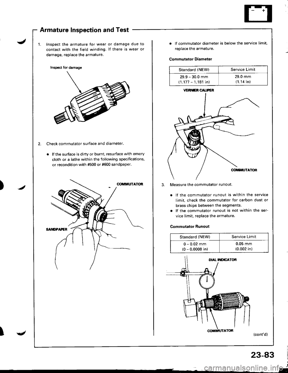
Armature Inspection and Test
Inspect the armature tor wear
contact with the field winding.
damage, replace the armature.
or damage due to
lf there is wear or
/)
2. Check comrnutator surface and diameter.
. lf the surface is dirty or burnt, resurface with emery
cloth or a lathe within the following specifications,
or recondition with #500 or #600 sandpaper.
gt
Inspsct for damage
. lf commutator diameter is below the service limit,
replace the armature.
Commutator Diameter
Measure the commutator runout.
. lf the commutator runout is within the service
limit, check the commutator lor carbon dust or
brass chips between the segments.
. lf the commutator runout is not within the ser-
vice limit, replace the armature.
Commutator Runout
(cont'd)
23-83
Standard (NEW)Service Limil
29.9 - 30.0 mm
(1.177 - 1.181 in)
29.0 mm
(1.14 in l
VERI{ER CAI|PEN
Standard (NEW)Service Limit
0 - 0.02 mm
(0 - 0.0008 in)
u-(J5 mm
(0.002 in)
Page 1141 of 1681
Starting System
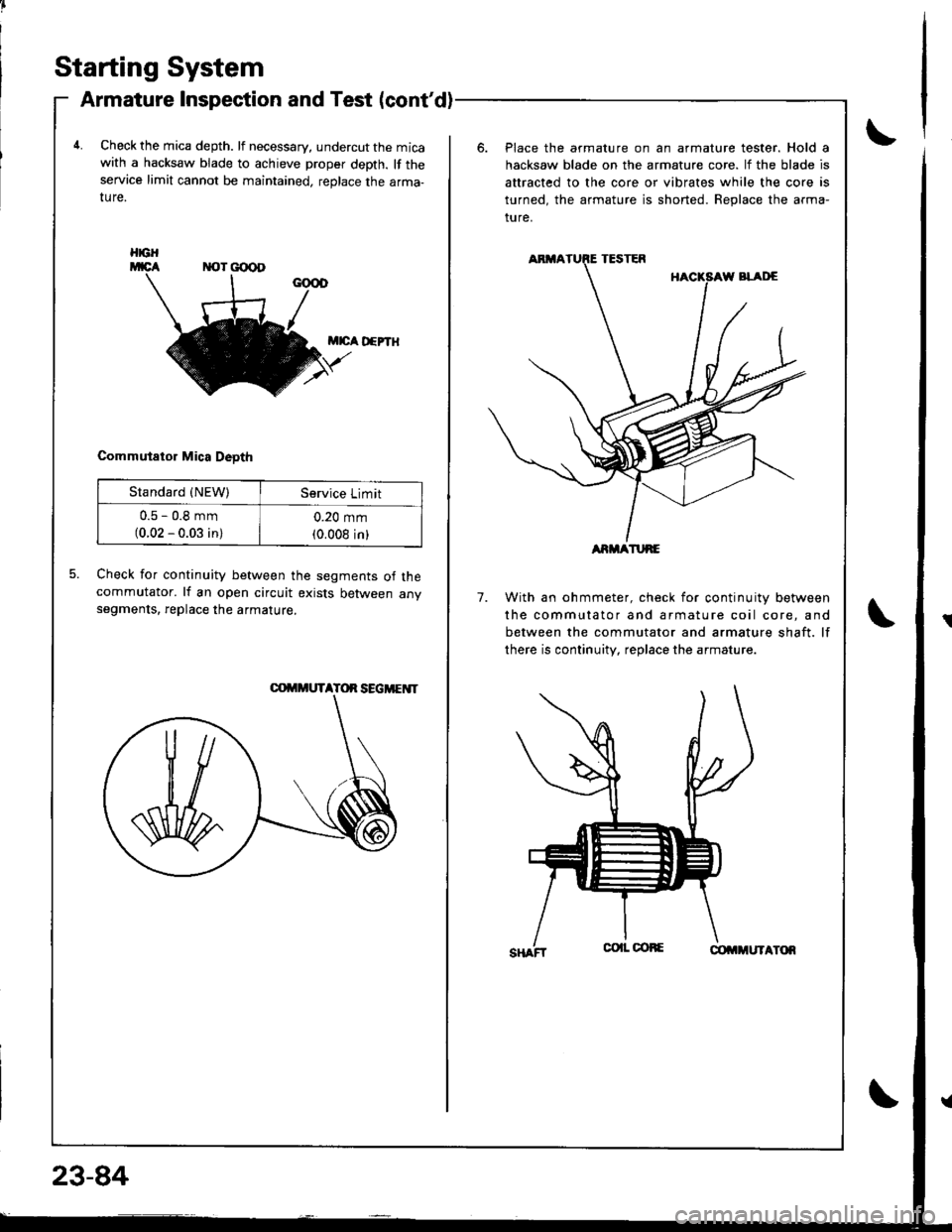
Armature Inspection and Test (cont'd)
4.Check the mica depth. lf necessary, undercut the micawith a hacksaw blade to achieve proper depth. lf theservice limit cannot be maintained, replace the arma-ture.
Place the armature on an armature tester. Hold a
hacksaw blade on the armature core. lf the blade is
attracted to the core or vibrates while the core is
turned, the armature is shorted. Beplace the arma-
ture.
M|cA D€PTH
Commutator Mica Deoth
5.Check for continuity between the segments of thecommutator. lf an open circuit exists between anvsegments, replace the armature.7.With an ohmmeter, check for continuity between
the commutator and armature coil core, and
between the commutator and armature shaft. lf
there is continuity, replace the armature.
HGH
Standard {NEW)Service Limit
u.5 - u,6 mm(0.02 - 0.03 in)
0.20 mm(0.008 inlARMATURE
Page 1145 of 1681
lgnition System
23-88
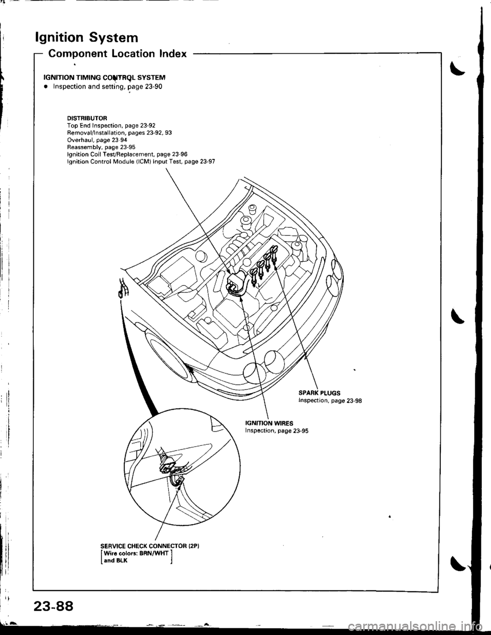
Component Location lndex
rGNlTroN TTMTNG COJTRqL SYSTEM
. lnspection and sefting, page 23-90
DISTRIBUTORTop End lnspeclion, page 23-92Removal/lnstallation, pages 23-92, 93Overhaul, page 23 94Reassembly, page 23-95lgnition Coil TesvReplacement, page 23 96lgnition Control Module (lCM) lnput Test, page 23-97
PLUGSInspection, pago 23-98
IGN'TION WIRESInspection, page 23-95
SERVICE CHECK CONNECTOR I2PIIWi]6 coloEi BRN/WHT I
land BLK j
Page 1164 of 1681
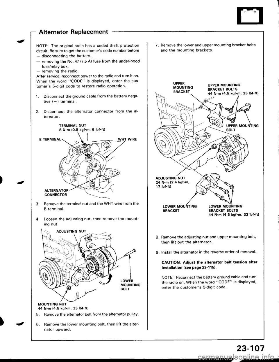
Alternator Replacement
)
t
-
NOTE: The original radio has a coded theft protection
circuit. Be sure to get the customer's code number before
- disconnecting the battery.
- removing the No. 47 (7.5 A) fuse from the under-hood
fuse/relay box.
removing the radio.
After service, reconnect power to the radio and turn it on.
When the word "CODE" is displayed, enter the cus
tomer's s-digit code to restore radio operation.
1. Disconnect the ground cable from the battery nega-
tive (- ) terminal.
2. Disconnect the alternator connector from the al-
lernalor,
TERMINAL NUT8 N,m (O.8 kgf'm, 6 lbl'ft)
B TERMINAL
ALTERNATORCONNECTOR
Remove the terminal nut and the WHT wire from the
B terminal.
Loosen the adjusting nut, then remove the mount-
Ing nut.
MOUNTINGBOLT
MOUNTING NUT44 N.m (4.5 kgf.m.33 lbt.ftl
5. Remove the alternator belt from the alternator pulley.
6. Remove the lower mounting bolt, then lilt the alter-
naror upwaro.
3.
{--,
7.Remove the lower and upper mounting bracket bolts
and the mounting brackets.
BRACKET BOLTSil4 N.m {4.5 kgl.m, 33 lbt.ft)
8. Remove the adiusting nut and upper mounting bolt,
then lift out the alternator.
9. lnstallthe alternator in the reverse order of removal.
CAUTION: Adiust the alternator belt tension aftsr
installation lseo page 23-1151.
NOTE: Reconnect the battery ground cable and turn
the radio on. When the word "CODE" is displayed,
enter the customer's s-digit code.
BRACKET
UPPER MOUNTINGBRACKET EOLTS44 N.m {4.5 kgl.m, 33 lbl'ft)
24 N.m (2.4 kgf.m,17 rbf.ftl
b-h..K
) I
23-107
-
,-
Page 1166 of 1681
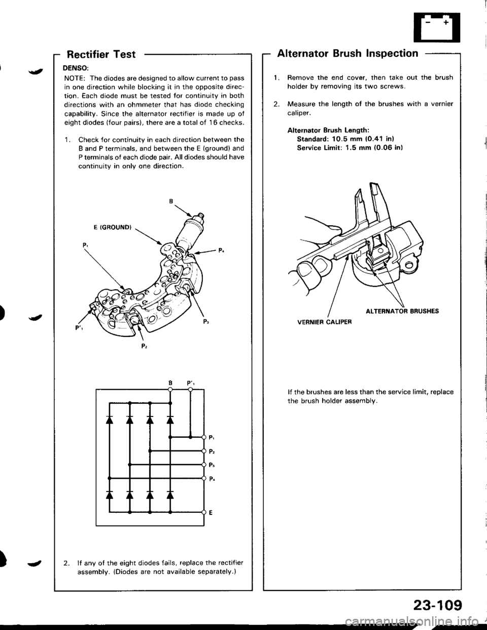
RectifierTest
DENSO:
NOTE: The diodes are designed to allow current to pass
in one direction while blocking it in the opposite direc-
tion. Each diode must be tested tor continuity in both
directions with an ohmmeter that has diode checking
capability. Since the alternator rectifier is made up ot
eight diodes (four pairs), there are a total of 16 checks.
'1. Check for continuity in each direction between the
B and P terminals, and between the E (ground) and
P terminals of each diode pair. All diodes should have
continuity in only one direction.
lf any of the eight diodes fails, replace the recti{ier
assembly. iDiodes are not available separately.)
2.
AlternatorBrushInspection
l.Remove the end cover, then take out the brush
holder by removing its two screws.
Measure the length of the brushes with a vernier
caliper.
Altelnator Brush Length:
Standard: 1O.5 mm {O.41 in}
Service Limit: 1.5 mm (0.06 in)
2.
lf the brushes are less than the service limit, replace
the brush holder assembly.
VERNIER CALIPER)
{
J
)
23-109
J
.-
Page 1170 of 1681
i'[
Rotor Slip Ring TestAlternator Brush Inspection
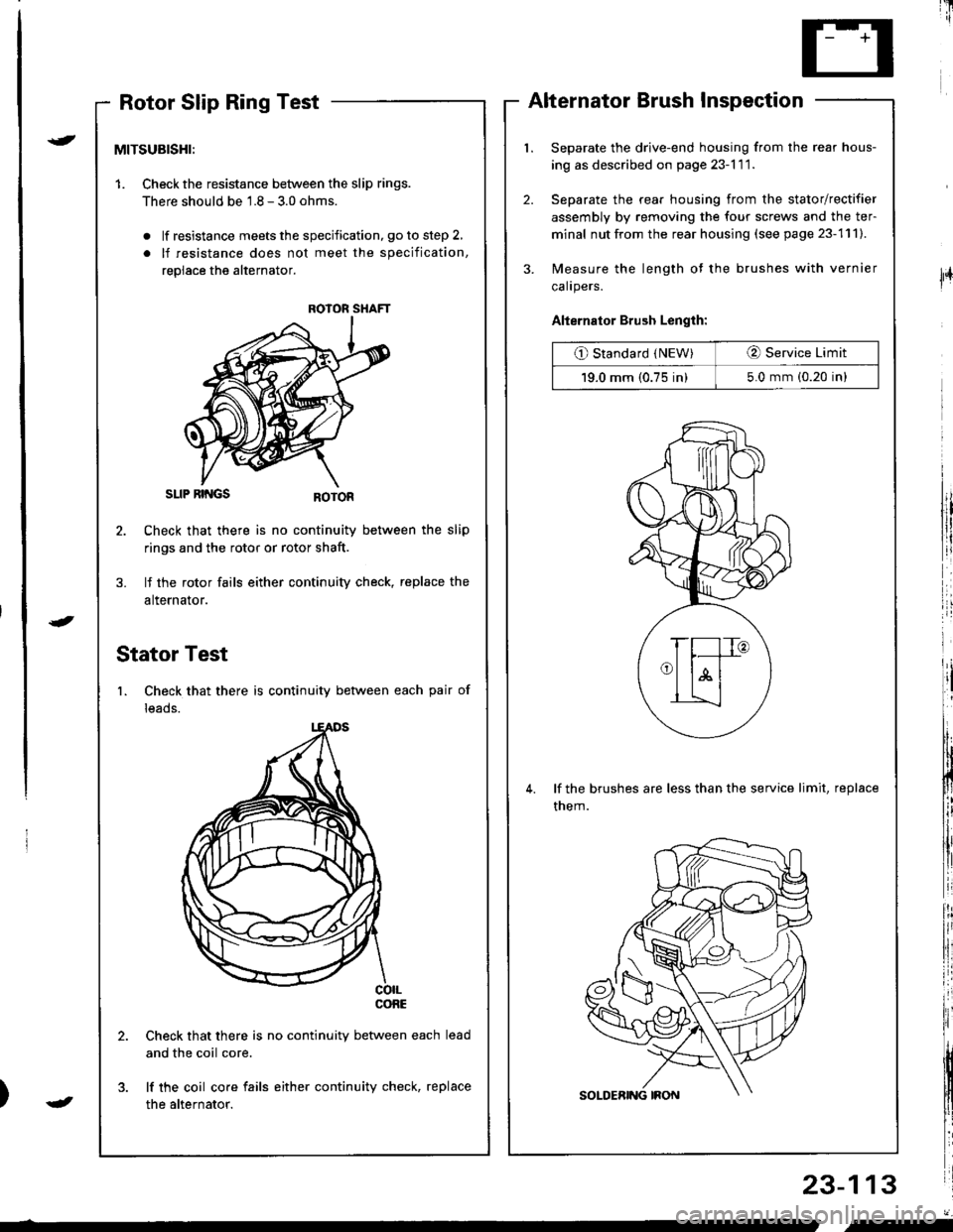
Separate the drive-end housing from the rear hous-
ing as described on page 23-l 1 1.
Separate the rear housing from the stator/rectifier
assembly by removing the four screws and the ter-
minal nut from the rear housing (see page 23-111).
Measure the length of the brushes with vernier
calrpers.
Alternator Brush Length:
O Standard (NEW)O Service Limit
19.0 mm (0.75 in)5.0 mm (0.20 in)
lf the brushes are less than the service limit, replace
them.
23-113
{
J
lFr
MITSUBISHI:
1. Checkthe resistance between the slip rings.
There should be 1.8 - 3.0 ohms.
. lf resistance meets the specification, go to step 2,
. lf resistance does not meet the specification,
replace the alternator.
SLIP RII{GS
Check that there is no continuity between the slip
rings and the rotor or rotor shaft.
lf the rotor fails either continuity check, replace the
alternator.
Stator Test
1. Check that there is continuity between each pair of
leads.
co|LconE
Check that there is no continuity between each
and the coil core.
lf the coil core fails either continuity check, replace
the alternator.
ROIOR SHAFT
J
"-
Page 1203 of 1681
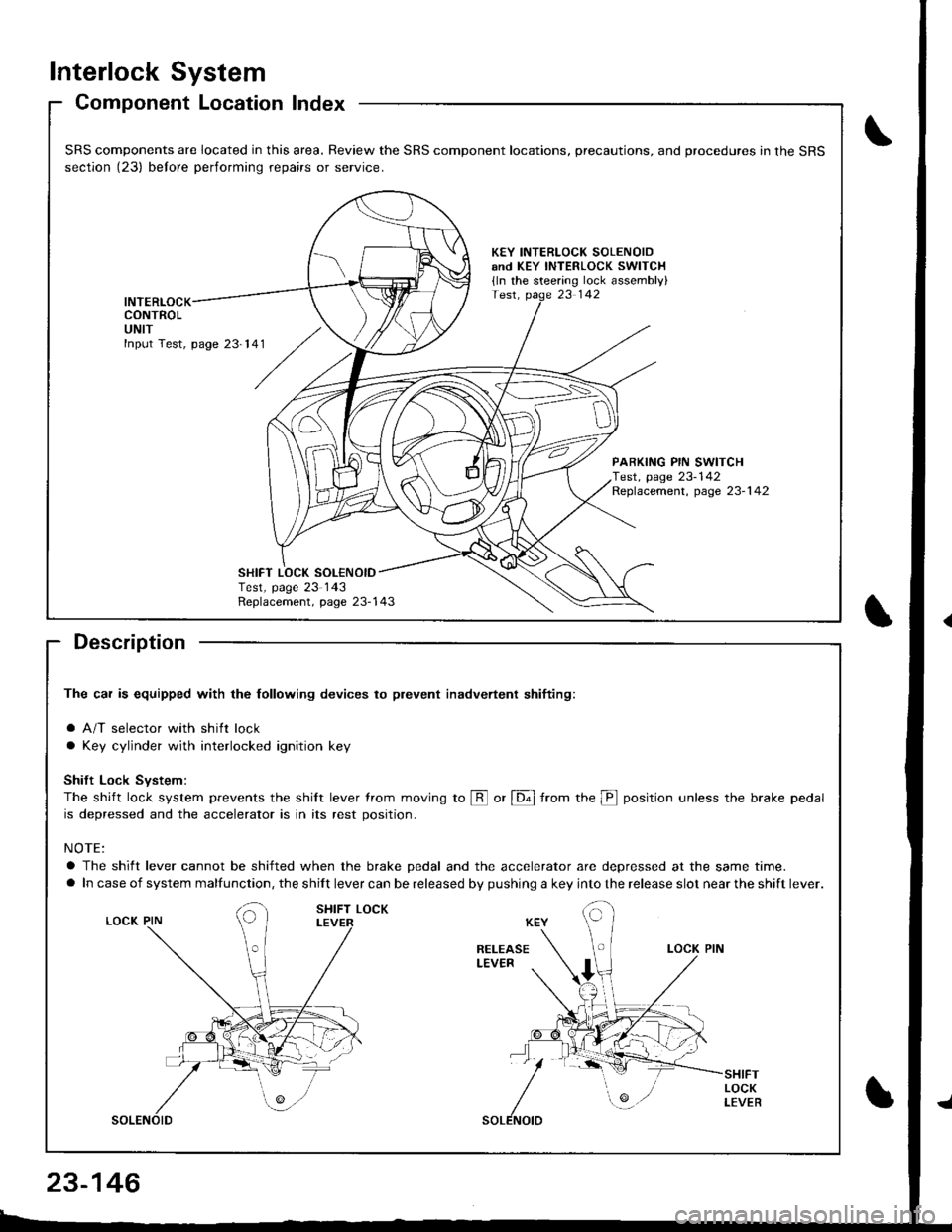
Interlock System
Component Location Index
Description
The car is equipped with the lollowing devices to plevent inadvertent shifiing:
a A/T selector with shift lock
a Key cylinder with interlocked ignition key
Shift Lock Svstem:
The shift lock system prevents the shilt lever trom moving to @ or [6ol from the p position unless the brake pedal
is depressed and the accelerator is in its rest position.
NOTE:
a The shift lever cannot be shifted when the brake pedal and the accelerator are depressed at the same time.
a In case of system malfunction, the shift lever can be released by pushing a key into the release slot near the shift lever.
SRS components are located in this area. Review the SRS component locations, precautions, and procedures in the SRS
section (23) belore performing repairs or service.
KEY INTERLOCK SOLENOIDand KEY INTERLOCK swlTCH
{ln the steering lock assembly}
INTERLOCKCONTROLUNIT
PARKING PIN SWITCHTest, page 23-142Replacement, page 23-1 42
Replacement, page 23-143
SHIFT LOCK SOL€NOIDTest, page 23 143
23-146
Page 1253 of 1681
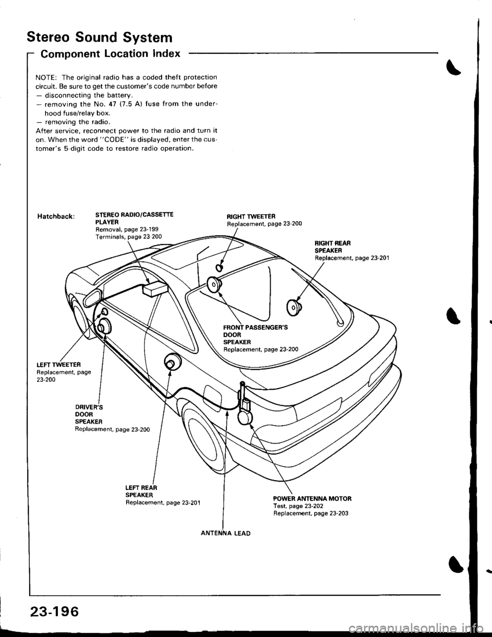
Stereo Sound System
Component Location Index
DOORSPEAKERReplacement, page 23-2OO
NOTE: The original radio has a coded theft protection
circuit. Be sure to get the customer's code number betore- disconnecting the battery.- removing the No.47 (7.5 A) fuse from the under-
hood fuse/relay box.- removing the radio.
After service, reconnect power to the radio and turn it
on. When the word "CODE" is displayed, enter the cus-
tomer's 5 digit code to restore radio operation.
STEREO RADIO/CASSETTEPLAYERRemoval, page 23-199Terminals, page 23 200
RIGHT TWEETERReplacement, page 23'200
BIGHT REARSPEAKERReplacement, page 23-201
LEFT REARSPEAKERReplacement, page 23,201POWER ANTENNA MOTORTest, page 23-202Replacernent, page 23-203
23-196
Page 1256 of 1681
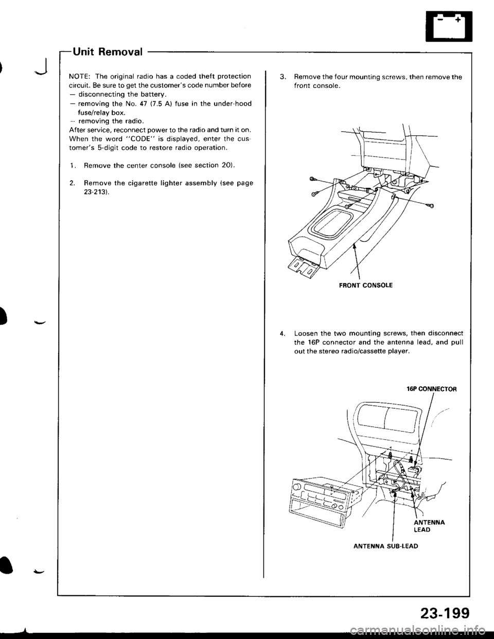
Unit Removal
NOTE: The original radio has a coded thelt protection
circuit. Be sure to get the customer's code number before- disconnecting the battery.- removing the No. 47 (7.5 A) fuse in the under-hood
fuse/relay box.- removing the radio.
After service. reconnect power to the radio and turn it on.
When the word "CODE" is displayed, enter the cus-
tomer's 5-digit code to restore radio operation.
'1. Remove the center console (see section 20).
2. Remove the cigarette lighter assembly (see page
23-2131.
)
FRONT CONSOLE
Remove the four mounting screws, then remove the
front console.
Loosen the two mounting screws. then disconnect
the 16P connector and the antenna lead, and Dull
out the stereo radio/cassette plaver.
16P CONNECTOR
ANTENNA SUB-LEAD
23-199