service HONDA INTEGRA 1998 4.G Repair Manual
[x] Cancel search | Manufacturer: HONDA, Model Year: 1998, Model line: INTEGRA, Model: HONDA INTEGRA 1998 4.GPages: 1681, PDF Size: 54.22 MB
Page 620 of 1681
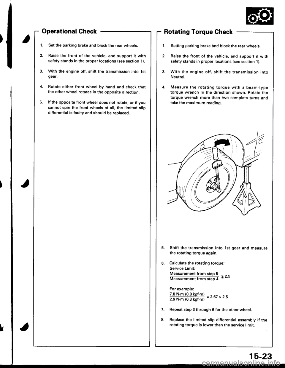
Operational Check
Set the parking brake and block the rear wheels.
Raise the front of the vehicle, and support it with
safety stands in the proper locations (see section 1).
With the engine off, shift the transmission into lstgear,
Rotate either front wheel bv hand and check that
the other wheel rotates in the opposite direction.
lf the opposite tront wheel does not rotste, or if voucannot spin the front wheels at all, the limited slip
differential is faulty and should be roplaced.
Rotating Torque Check
Setting parking brake and block the rear wheels.
Raise the front of the vehicle, and support it with
safety stands in proper locations (see section 1).
With the engine off, shift the transmission into
Neutral.
Measure the rotating torque with a beam-type
torquo wrench in the direction shown, Rotate the
torque wrench morg than two complete turns and
take the maximum reading.
Shift the transmission into 1st gear and measure
the rotating torque again.
Calculate the rotating torque:
Service Limit:
Measur€ment from steD 5
Measurementfrom step 4 =--
For example:
7.8 N.m (0.8 kgf.m)
zg N"ll (03 kgf'ntl = z'ot > z''
Repeat step 3 through 6 for the other wheel.
Replace the limited slip differential assembly if the
rotsting lorque is lower than the service limit.
!
15-23
Page 650 of 1681
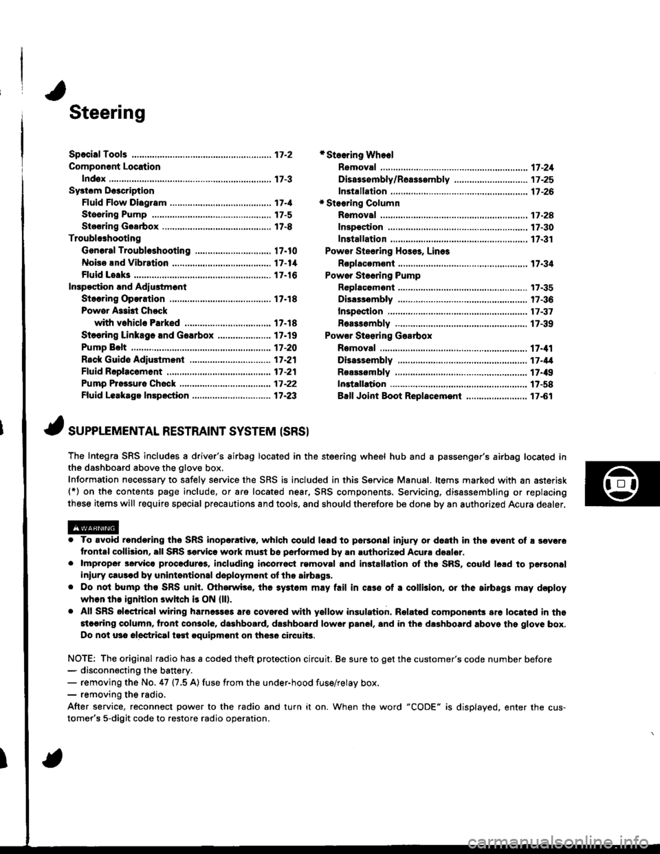
Steering
Componsnt Location
lndox
*Stooring Wheel
Removal ....
Disassombly/Ro8$.mbly
Disassombly ......
F08$€mbly
Powcr Stosring Gosrbox
R6moval
............................ 17-3
............. 17 -1
................ 17-16
............................. 17_25
17-30
17.31
.......17-21
Sy3tom DGcription
Fluid Flow Disgram
Steering Pump .............. 17-5
Stocring Goarbox ...17.8
Troublorhooting
Gonoral Troubleshooting .............................. 17.10
Noiso lnd Vibration ...... 17-1i[
Fluid Losk3
lnspoction
Installation
Powor Steering Hos6, Lino3
Roplacom€nt .................. 17.34
Powor Steoring Pump
RGplac6montlolpeqtion lnd Adiu3tm6nl
Stoo.ing Operation
Powor A$bi Chock
with v.hiclo Parked
Stcering Linkage 6nd Goarbox
Pump Bolt
17.18
17.18
17.19
17-20
17.35
t7-36
17 -37
r7-39
Inspoction
................... 17.41
Rack Guide Adiustmont ..........................-.-.-. 17 -21
Ffuid Rcplacemont ........17-21
Pump Prc&suro Chock ...,........................,..,..., 17 -22
Fluid Leakage Inrpection ............................... 17-23
Dissssembly
R€aEs€mbly
In3tallation........... 17_58
Ball Joint Boot Replacem.ni ........................ 17-61
17-U
17.49
J ,urrar*TNTAL REsrRArNr sysrEM (sRsr
The Integra SRS includes a driver's airbag located in the steering wheel hub and a passenger's airbag located inthe dashboard above the glove box,
Information necessary to safely service the SRS is included in this Service Manual. ltems marked with an asterisk(*) on the contents page include, or are located near, SRS components. Servicing, dissssembling or replacing
these items will require special pr6cautions and tools, and should therefore be done by an authorized Acura dealer.
. To avoid rondoring ths SRS inoparstivo. which could |rad to parsonal iniury or doath in the ov€nt of ! sev6.o
trontal collision, all SRS sarvice work must be perto.med by an authorizod Acura dsalor.. lmpropor 3orvic€ procadures, including inco[6ql rgmoval and inrtallation of the SRS, could l6ad to pgrsonal
iniury clus€d by unintentional doployment of the airbags,. Do nol bump tho SRS unh, (Xherwise, th6 3ystom may fail in cas€ ol a collision, or the airbags may d€ploy
when ths ignition switch is ON {ll).. All SRS electrical wiring harness€s aro covered with yallow insulation. Related component3 are located in ths
stcaring column. tront con3ol6, dashboard, d.shbolrd lower panel, and in the dashboard above ths glove box.
Do not u3o electrical test oquipm€nt on the3e circuii3.
NOTE: The original radio has a coded theft protection circuit. Be sure to get the customer's code number before- disconn€cting the battery.- removing the No. 47 (7.5 A) fuse from the under-hood fuse/relay box,- removing the radio.
After service, reconnect power to the radio and turn it on. When the word "CODE" is displayed. enter the cus-
tomer's 5-digit code to restore radio operation.
Page 652 of 1681
I
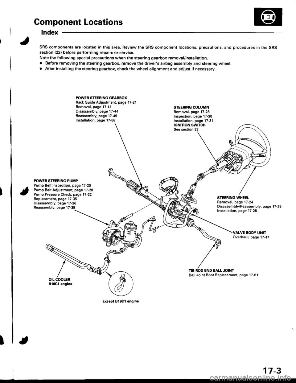
Component Locations
Index
SRS components are located in this area. Review the SRS component locations, precautions, and procedures in the SRSsection (23) before performing repairs or service.
Note the following special precautions when the steering gearbox removal/installation,
. Before removing the steering gearbox, remove the driver's airbag assembly and steering wheel.
. After installing the steering gearbox, ch6ck the wheel alignmentand adjust if necessary.
POWER STEERING GEARBOXRack Guid€ Adjustment, page 17 -21
Removal, pago 17-4'1Disassembly, page 17-44Reassombly. page'17-49Installation, page 17-58
STEEBING COLUMNRemoval. page 17-28Inspection, pago 17-30Installation, page 17-3'1|GNMON SWITCHSee section 23
POWER STEERING PUMPPump Belt Inspection. page 17-20Pump Belt Adjustment, page 17 -20
Pump Pr€ssuro Check, page 17'22Roplacament, page 17-35Dis686embly, page 17-36Reassembly, page 17-39
STEEBING WHEELRomoval, page 17-24Disassembf y/Reassembly, paga 17 -25
Installation, page 17-26
TIE.BOD END BALL JOINTBallJoint Boot Replacement, page 17-61
Exc.pt BlSCl onginc
17-3
Page 667 of 1681
Inspection and Adjustment
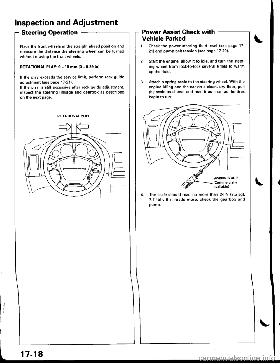
Steering Operation
Place the front wheels in the straight ahead position and
measure the distance the steering wheel can be turned
without moving the front wheels.
ROTATIONAL PLAY: 0 - 10 mm {0 - 0.39 inl
lf the play exceeds the service limit. perform rack guide
adiustment (see page 17-211.
lf the play is still excessive after rack guide adjustment.
inspect the steering linkage and gearbox as described
on the neld page.
Power Assist Check with
Vehicle Parked
Check the power steering fluid level (see page 17-
21) and pump belt tension (see page 17-201.
Start the engine, allow it to idle. and turn the steer
ing wheel from lock-to-lock several times to warm
up the fluid.
Attach a spring scale to the steering wheel. With the
engine idling and the car on a clean. dry floor. pull
the scale as shown and read it as soon as the tires
begin to turn,
4. The scale should read no more than 34 N (3.5 kgf,
7.7 lbf). lf it reads more, check the gearbox and
pump.
ROTATIONAL PLAY
Page 674 of 1681
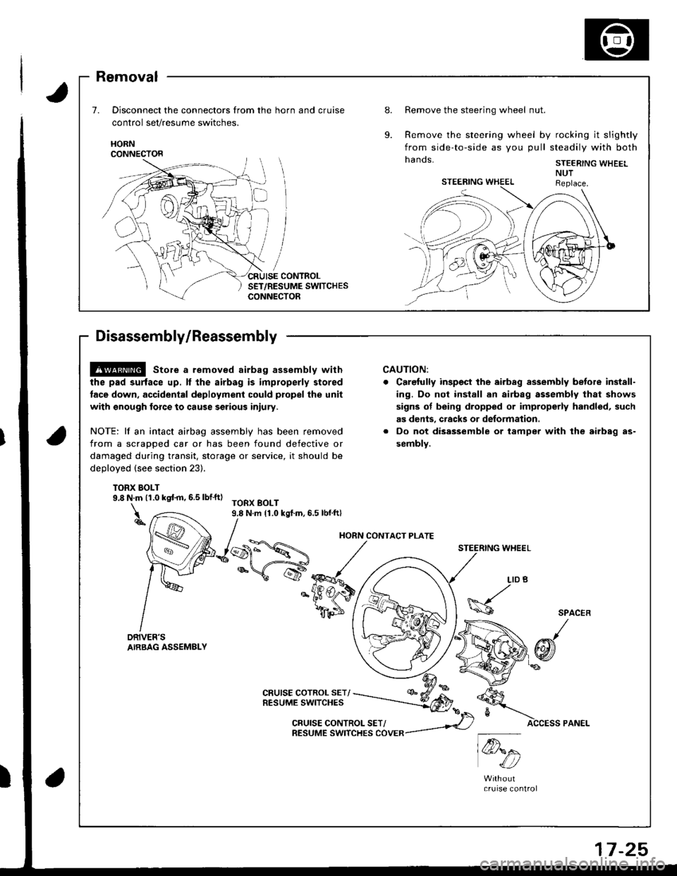
Removal
Disconnect the connectors from the horn and cruise
control set/resume switches.
Remove the steering wheel nut.
Remove the steering wheel by rocking it slightly
from side-to-side as you pull steadily with both
hands. STEER|NG WHEEL
HORNCONNECTOR
7 -25
@ store a removed airbag assembly with
the pad surtace up. ll the airbag is improperly stored
tace down. accidental deployment could propel the unit
with snough force to cause serious iniury.
NOTE: lf an intact airbag assembly has been removed
from a scrapped car or has been found defective or
damaged during transit, storage or service, it should be
deDloyed (see section 23).
TORX BOLT9.8 N.m (1.0 kqt m, 6.5 lbf'ft)TORX BOLT9.8 N.m 11.0 kgf.m,6.5 lbf.ft)
CRUISE COTROL SET/RESUME SWITCHES
CAUTION:
Carefully inspect the airbsg assembly betore inst8ll-
ing. Do nol install 8n airbag assembly that shows
signs ot being dropped or improperly handled, such
as dents, cracks or deformation.
Oo not disassemble or tampel with the airb8g as-
sembly.
STEERING WHEEL
\@.
LID
h6
w1c4:,/bA
4t
SPACER
@f
CRUISE CONTROL SET/RESUME SWITCHES COVER
HORN CONTACT PLATE
Page 717 of 1681
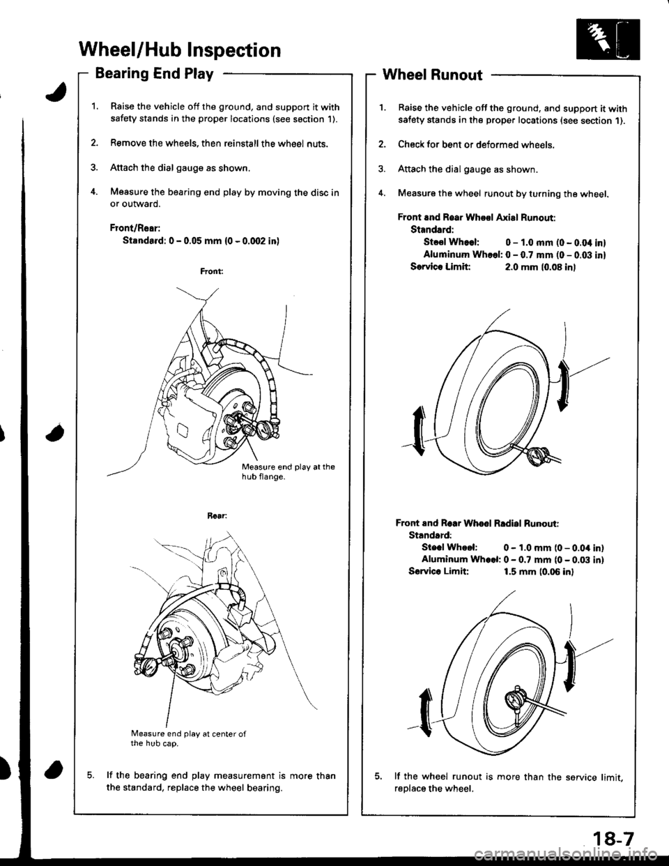
Wheel/Hub Inspection
Bearing End Play
Raise the vehicle off the ground, and support it with
safety stands in the proper locations (see saction 1).
Remove the wheels, then reinstallthe whe6l nuts.
Attach the dial gauge as shown.
Measure the bearing end play by moving the disc in
or outward.
Front/Rear:
Standa.d: 0 - 0.05 mm (0 - 0.qr2 in)
a
Measure end play at center ofthe hub cap.
lf the bearing end play measurement is
the standard, replace the wheel bearing.
Wheel Runout
Raise the vehicle off the ground, and support it withsatety stands in the proper locations (see section 1).
Check for bent or deformed wheels.
Attach the dial gauge as shown.
Measure the wheel runout by turning the wheel.
Front and Roar Whool Axial Runout:
Standard:
Stcsl Whoel: 0 - 1.0 mm (0 - 0.04 inl
Aluminum Whcel: 0 - 0.7 mm (0 - 0.03 inl
Sorvlc. Limit:2.0 mm (0.08 inl
Front End Roar Whod Rldisl Runouti
Standard:
Ste.l Whool: 0 - 1.0 mm (0 - 0.04 inlAluminum Wh.el: 0 - 0.7 mm (0 - 0.03 inl
Sorvico Limit:1.5 mm (0.06 inl
lf the wh€el runout is more than the service limit,
reDlace the wheel.
more than
18-7
Page 760 of 1681
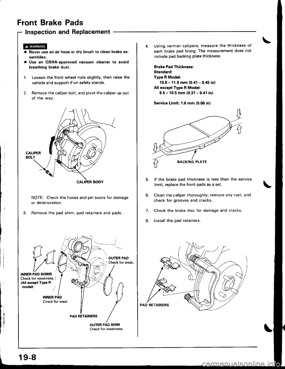
Front Brake Pads
Inspection and Replacement
fi
1i
INNER PAO SHIMSCheck lor weakness.(All .xc.pt Typc Rmodoll i
INNER PADCheck for woar.
a Never use an air hose or dry blush to clean brake as-
sembiles.a Use an OsHA-approved vacuum cleaner to avoid
breathing brak€ dust.
1. Loosen the Jront wheel nuts slightly, then raise the
vehicle and support if on satety stands,
2. Remove the caliper bolt, and pivot the caliper up out
of the wav.
NOTE: Check the hoses and pin boots for damage
or deterioration.
Remove the pad shim, pad retainers and pads.
OUIER PADCheck tor wear.
PAD RETAINERS
19-8
Using vernier calipers, measure the thickness ot
each brake pad lining. The measurement does not
include pad backing plate thickness.
Brako Pad Thickness:
St8ndard:
Type R Modol:
10.5 - 11.5 mm {0.41 - 0.45 in}
All except Type R Model:
9.5 - 10.5 mm (0.37 - O.ial inl
Service Limit: 1.6 mm (0.06 inl
lf the brake pad thickness is less than the service
limit, replace the front pads as a set,
Clean the caliper thoroughly; remove any rust, and
check tor grooves and cracks.
Check the brake disc for damage and cracks.
Install the pad retainers.
6.
7.
8.
Page 762 of 1681
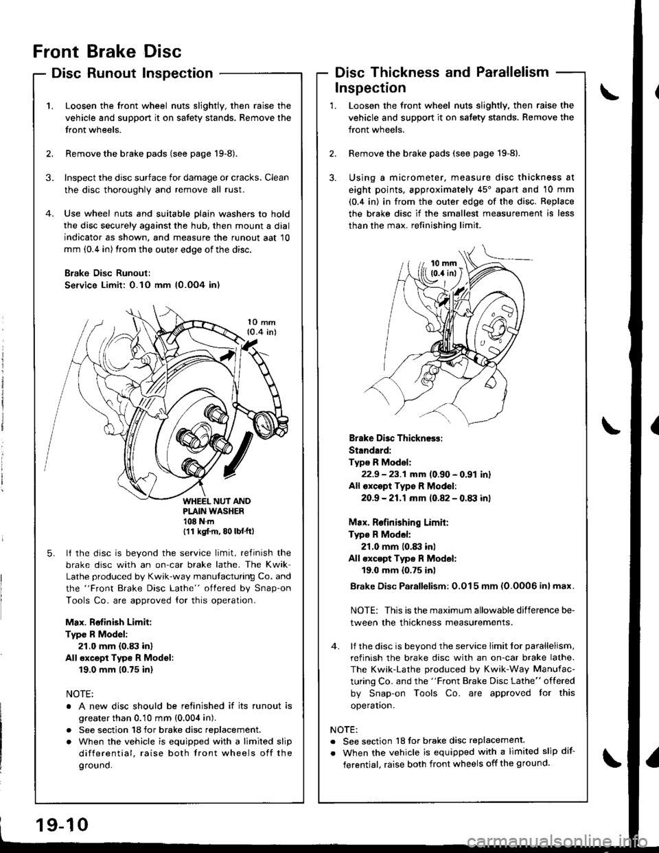
Front
Disc
Brake
Runout
Disc
InspectionDisc Thickness and Parallelism
\'L
2.
Loosen the front wheel nuts slightly, then raise the
vehicle and suppon it on safety stands. Remove the
front wheels.
Remove the brake pads (see page 19-8).
Inspect the disc surface for damage or cracks. Clean
the disc thoroughly and remove all rust.
Use wheel nuts and suitable plain washers to hold
the disc securely against the hub, then mount a dial
indicator as shown, and measure the runout aat 10
mm (0.4 in) from the outer edge of the disc.
B;ake Disc Runoul:
Service Limit: 0.10 mm (0.OO4 in)
3.
1O mm{0.4 inl
PLAIN WASHER108Nm(11 ksl.m, 80 lbf.ft)
5. lf the disc is beyond the service limit, refinish the
brake disc with an on-car brake lathe. The Kwik
Lathe produced by Kwik-way manutacturing Co. and
the "Front Brake Disc Lathe" oflered by Snap-on
Tools Co. are approved {or this operation.
Max. Rofinish Limit:
Type R Model:
21.0 mm (0.83 in)
All €xcept Type R Model:
19.0 mm (0.75 inl
NOTE:
o A new disc should be relinished if its runout is
greater than 0.10 mm (0,004 in).
. See section 18 for brake disc replacement.
. When the vehicle is equipped with a limited slip
differential, raise both front wheels off the
ground.
3.
Loosen the front wheel nuts slightly, then raise the
vehicle and support it on safety stands, Remove the
front wheels.
Remove the brake pads (see page 19-8).
Using a micrometer, measure disc thickness at
eight points, approximately 45'apart and 10 mm
(0.4 in) in from the outer edge of the disc. Replace
the brake disc if the smallest measurement is less
than the max. refinishing limit.
Inspection
2.
1.
Brake Disc Thickness:
Standard:
Type R Model:
22.9 - 23.1 mm (0.90 - 0.91 inr
All oxcept Typ€ R Mod€l:
2O.9 -21.1mm 10.82 - 0.tB inl
Max. Relinishing Limit:
Type R Model:
21.0 mm 10.83 inl
All €xc€pt Type R Model:
19.0 mm {0.75 inl
Brake Disc Parallelism: O.O15 mm (0.0006 inl max.
NOTE: This is the maximum allowable difference be-
tween the thickness measurements.
4. lf the disc is beyond the service limit lor parallelism,
refinish the brake disc with an on-car brake lathe.
The Kwik-Lathe produced by Kwik-Way Manufac-
turing Co. and the "Front Brake Disc Lathe" offered
by Snap-on Tools Co. are approved for this
operaton.
NOTE:
. See section 18 for brake disc replacement.
. When the vehicle is equipped with a limited slip dif-
ferentjal, raise both front wheels off the ground.
Page 768 of 1681
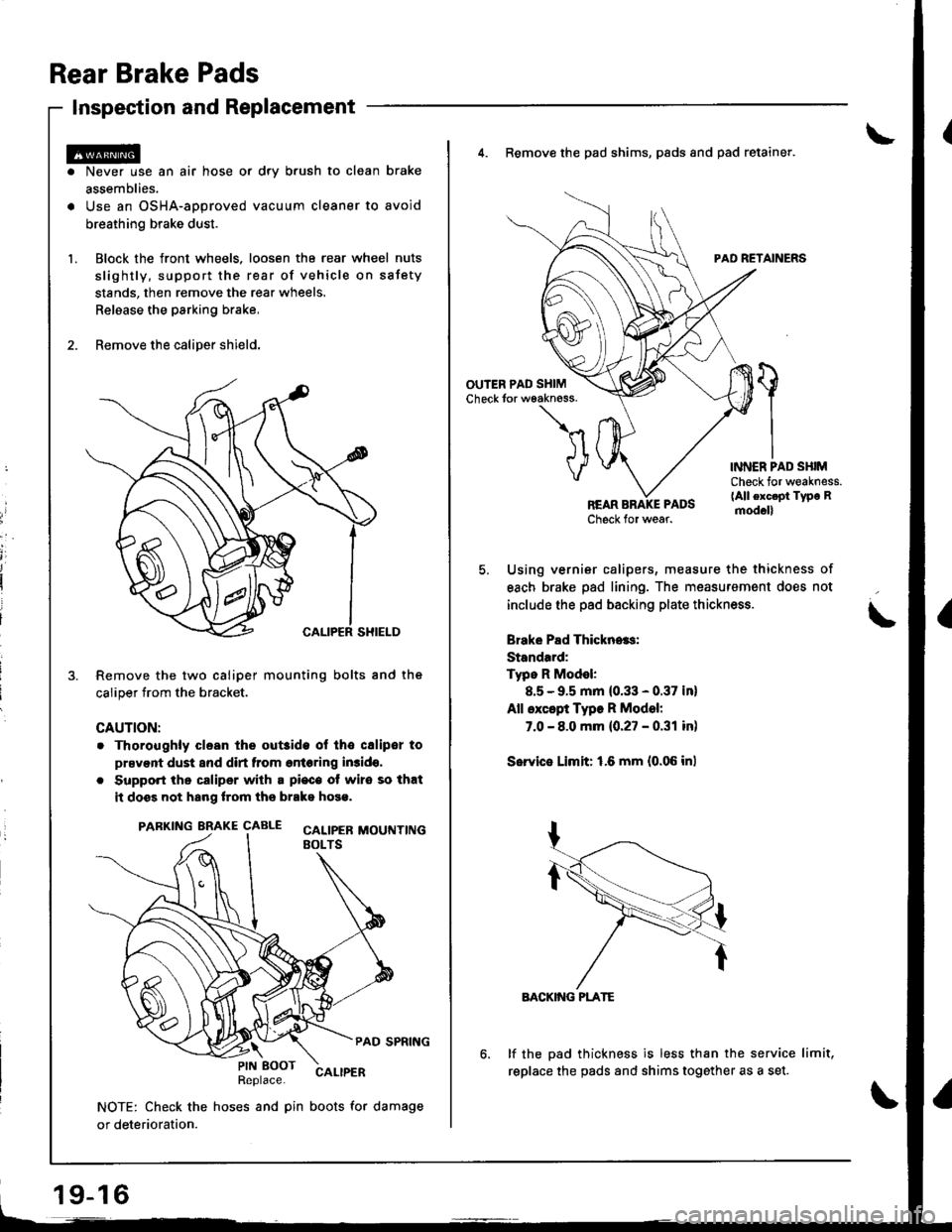
Rear Brake Pads
Inspection and Replacement
Never use an air hose or dry b.ush to clean brake
assemblies.
Use an OSHA-approved vacuum cleaner to avoid
breathing brake dust.
Block the front wheels. loosen tha rear wheel nuts
slightly, support the rear of vehicle on sstety
stands, then remove the rear wheels.
Relaase the parking brake,
Remove the caliper shield.
Remove the two caliper mounting bolts and the
caliper trom the bracket.
CAUTION:
. Thoroughly clesn the out3ide ol tho csliper to
prsvent dust and dirt from entering in3ido,
. Support the caliper with a pi€c€ ot wire so that
it doss not hang lrom ths brako hose.
PARKING BRAKE CAALE cALtpEB MOUTTT|NGEOLTS
PAD SPRING
Replace.CALIPER
NOTE: Check the hoses and pin boots for damage
or deterioration.
\PIN EOOT
19-16
4. Remove the pad shims, pads and pad retainer.
PAD RETAINERS
'l
VINNER PAD SHIMCheck for weakness.(All exc.pt Type Rmod.ll
Using vernier calipers, measure the thickness of
each brake pad lining. The measurement does not
include the pad backing plate thickness.
Brake Pad Thickn..s:
Standard:
Typo R Model:
8.5 - 9.5 mm (0.33 - 0.37 in)
All except Type R Model:
7.0 - 8.0 mm {0.27 - 0.31 in)
Sorvie Limit: 1.6 mm {0.06 inl
BACKIiIG PLATE
lf the pad thickness is less than the service limit,
replace the pads and shims together as a set.
Page 770 of 1681
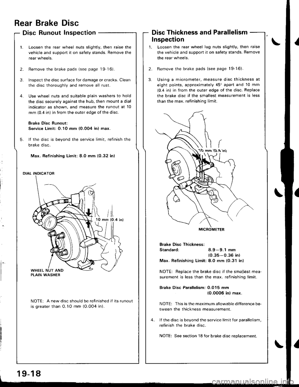
Inspection
rrii tlmm {0.4 inl10
l.
Rear Brake Disc
Disc Runout Inspection
Loosen the rear wheel nuts slightly, then raise the
vehicle and support it on safety stands. Remove the
rear wneers.
Remove the brake pads (see page 19-16).
Inspect the disc surface for damage or cracks. Clean
the disc thoroughly and remove all rust.
Use wheel nuts and suitable plain washers to hold
the disc securely against the hub, then mount a dial
indicator as shown, and measure the runout at 10
mm (0.4 in) in from the outer edge of the disc.
Brake Disc Runout:
Se.vice Limit: O.1O mm {0.0O4 in) max.
ll the disc is beyond the service limit, refinish the
brake disc.
Max. Refinishing Limit: 8.0 mm (0.32 in)
DIAL INDICATOR
NOTEi A new disc should be refinished if its runout
is greater than 0.'10 mm (O.O04 in).
Disc Thickness and Parallelism
Loosen the rear wheel lug nuts slightly, then raise
the vehicle and support it on safety stands. Remove
the rear wheels.
Remove the brake pads (see page 19-16).
Using a micrometer, measure disc thickness at
eight points, approximately 45" apart and 10 mm
(0.4 in) in from the outer edge of the disc. Replace
the brake disc if the smallest measurement is less
than the max. retinishing limit.
Bfake Disc Thickness:
Standard: 8.9 - 9.1 mm
(0.35-0.36 in)
Max. Refinishinq Limit:8.O mm (0.31 in)
NOTE: Replace the brake disc it the smaLlest mea-
surement is less than the max. retinishing limit.
Brake Disc Parallelism: O.O15 mm
(O.00O6 in) max.
NOTE: This is the maximum allowable difference be-
tween the thickness measurement.
lf the disc is bevond the service limit for parallelism,
refinish the brake disc.
NOTE: See section 18 for brake disc replacement.
\S rnrn .\'rn)
19-18