service HONDA INTEGRA 1998 4.G Manual Online
[x] Cancel search | Manufacturer: HONDA, Model Year: 1998, Model line: INTEGRA, Model: HONDA INTEGRA 1998 4.GPages: 1681, PDF Size: 54.22 MB
Page 953 of 1681
Dashboard
Replacement Precautions
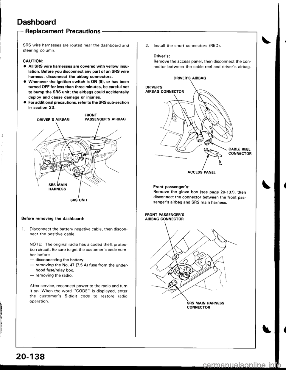
SRS wire harnesses are routed near the dashboard and
steenng column.
CAUTION:
a All SRS wire hsrnesses are covered wiih yellow insu-
lation. Before you disconnect any pan of an SRS wire
harness, disconnect the airbag conneclors.
a Whenever the ignition switch is ON (ll), or has been
tulned OFF for less than three minules, be careful not
to bump the SRS unit; the ai.bags could accidentally
deploy and cause damage or injuries.
a For additional precautions, refer lo the SRS sub-section
in section 23.
PASSENGER'S AIRBAG
Belore removing the dashboard:
1. Disconnect the battery negative cable, then discon-ne.r rhe n^.iriua.ahla
NOTEr The original radio has a coded thett protec,
tion circuit. Be sure to get the customer's code num
ber before- disconnecting the battery.- removing the No. 47 (7.5 A) fuse from the under-
hood tuse/relay box.- removing the radio.
After service, reconnect power to the radio and turn
it on. When the word "CODE" is displayed, enter
the customer's 5-digit code to restore radio
operation.
DRIVER'S AIRBAG
SRS UNIT
20-138
2.Install the short connectors (RED).
Driver's:
Remove the access panel, then disconnect the con-
nector between the cable reel and driver's airbag.
CABL€ REELCONNECTOR--_--._-_-----
Front passenger's:
Remove the glove box (see page 20-137), thendisconnect the connector between the front pas-
senger's airbag and SRS main harness.
FRONT PASSENGER'SAIRBAG CONNECTOR
SRS MAIN HARNESSCONNECTOR
ORIVER'S AIRBAG
Page 989 of 1681
lllustrated Index
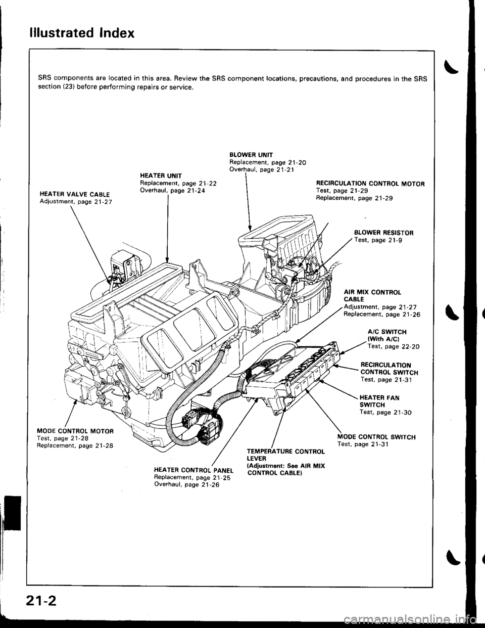
SRS components are located in this area. Review the SRS component locations. precautions, and procedures in the SRSsection (23) before performing repairs or service.
BLOWER UNITReplacement, page 21-2OOverhaul, page 21.21
HEATER VALVE CABLEAdiustment, page 21-27
HEATER UNITReplacement, page 21-22Overhaul, page 21-24RECIRCULATION CONTROL MOTORIest, page 21,29Seplacement, page 21-29
BLOWER RESISTORTest, page 21-9
AIR MIX CONTROLCABLEAdjustment, page 21-27Replacement, page 21-26
A/C SWTTCH{with A/clTest, page 22-20
RECIRCULATIONCONTROL SWITCHTest, page 21,31
HEATER FANswrTcHTest, page 21-30
MODE CONTROL MOTORTest, page 21-28Replacement, page 2 l -28CONTROL SWITCHTest, page 21-3'l
HEATER CONTROL PANELReplacement, page 21,25Overhaul, page 21-26
TEMPERATURE CONTROLLEVERlAdjustment: Soe AIR MIXCONTROL CABLEI
21-2
Page 1019 of 1681
Air Gonditioning
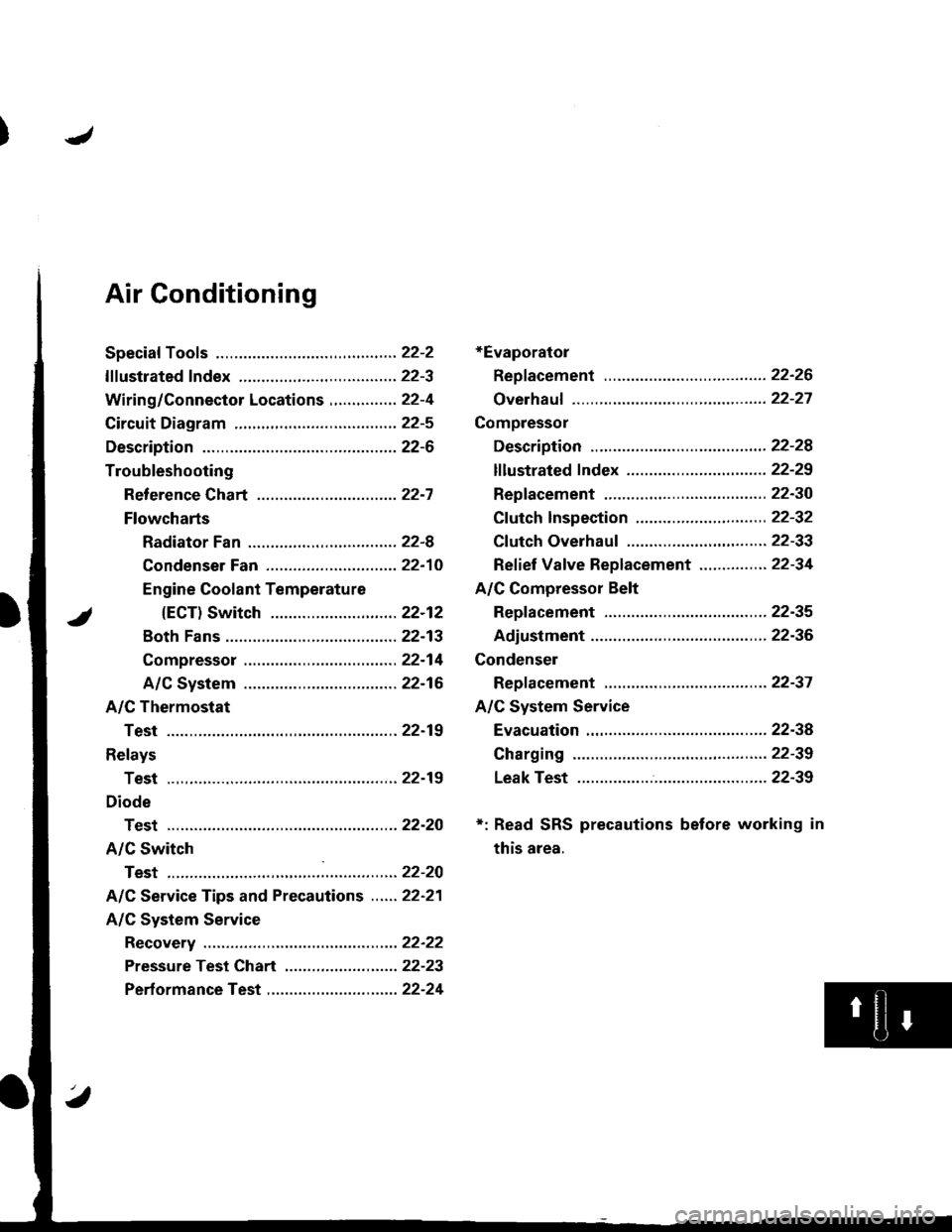
+Evaporator
Repf acement .........22-26
Overhauf ................22-27
Compressor
Description ............22-28
lf lustrated f ndex ............................... 22-29
Replacement .........22-30
Cf utch Inspection ....................... ...... 22-32
Cf utch Overhau1 ........................ ....... 22-33
Ref ief Vaf ve Replacement ............... 22-34
A/C Compressor Belt
Repf acement .........22-35
Adiustment ............22-36
Condenser
Repf acement .........22-37
A/C System Service
Evacuation .............22-38
Charging ................22-39
Leak Test ...............22-39
*: Read SRS precautions before working in
this area.
Page 1021 of 1681
lllustrated Index
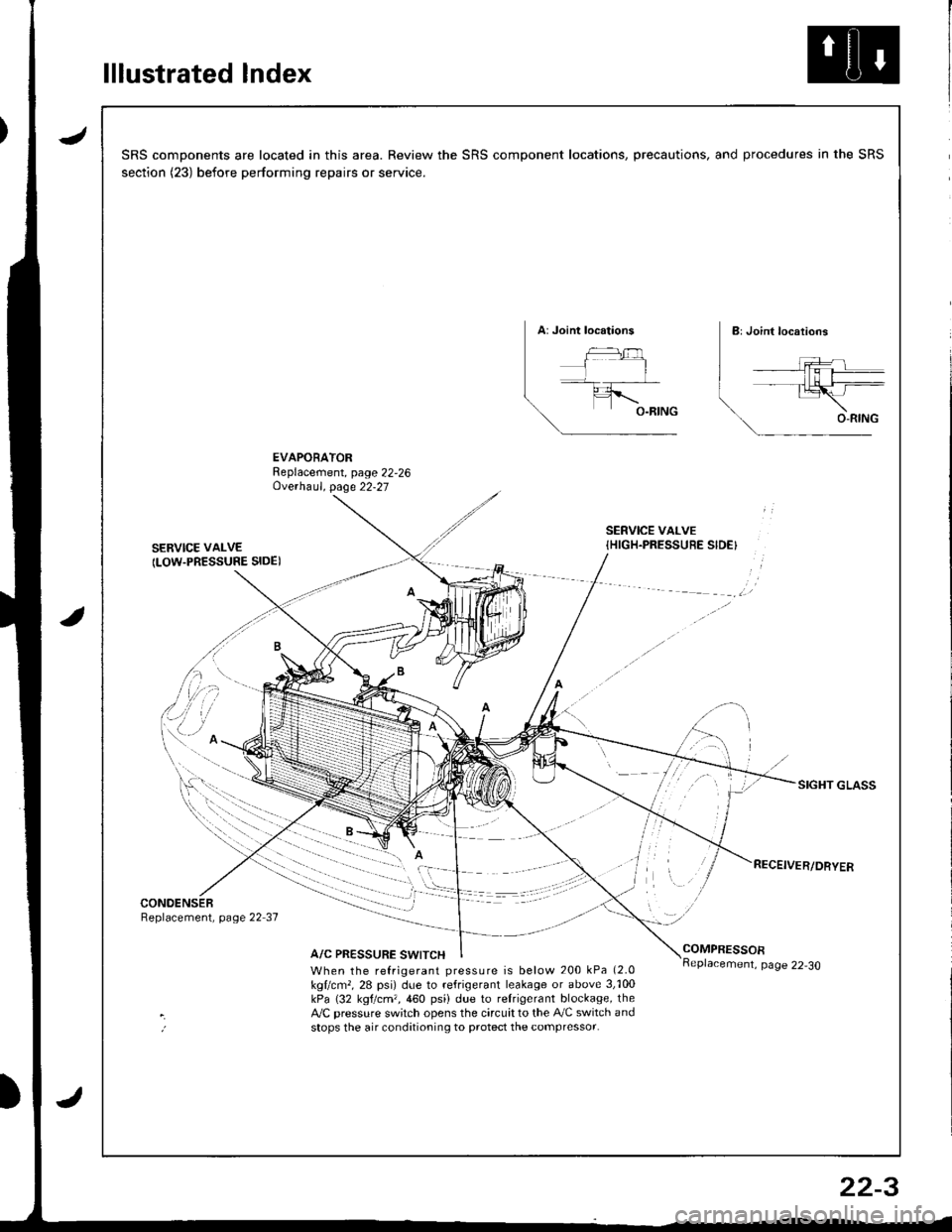
JSRS components are located in this area. Review the SRS component locations, precautions, and procedures in the SRS
section (23) before performing repairs or service.
EVAPORATORReplacement, page 22,26Ove.haul. page 22-27
SERVICE VAI-VE
ILOW.PRESSURE SIDE)
SERVICE VALVE{HIGH.PRESSUEE SIDE}
SIGHT GLASS
CONOENSERReplacement, page 22 37
A/C PRESSURE SWITCHCOMPRESSOR
When the refrigerant pressure is below 200 kPa (2.0
kgllcm,, 28 psi) due to refrigerant leakage or above 3,'100kPa (32 kgtcm,,460 psi) due to relrigerant blockage, theA,/C pressure sw;tch opens the circuit to the A,/C switch andstops the air conditioning to protect the compressor.
page 22-30
22-3
Page 1024 of 1681
Description
Outline
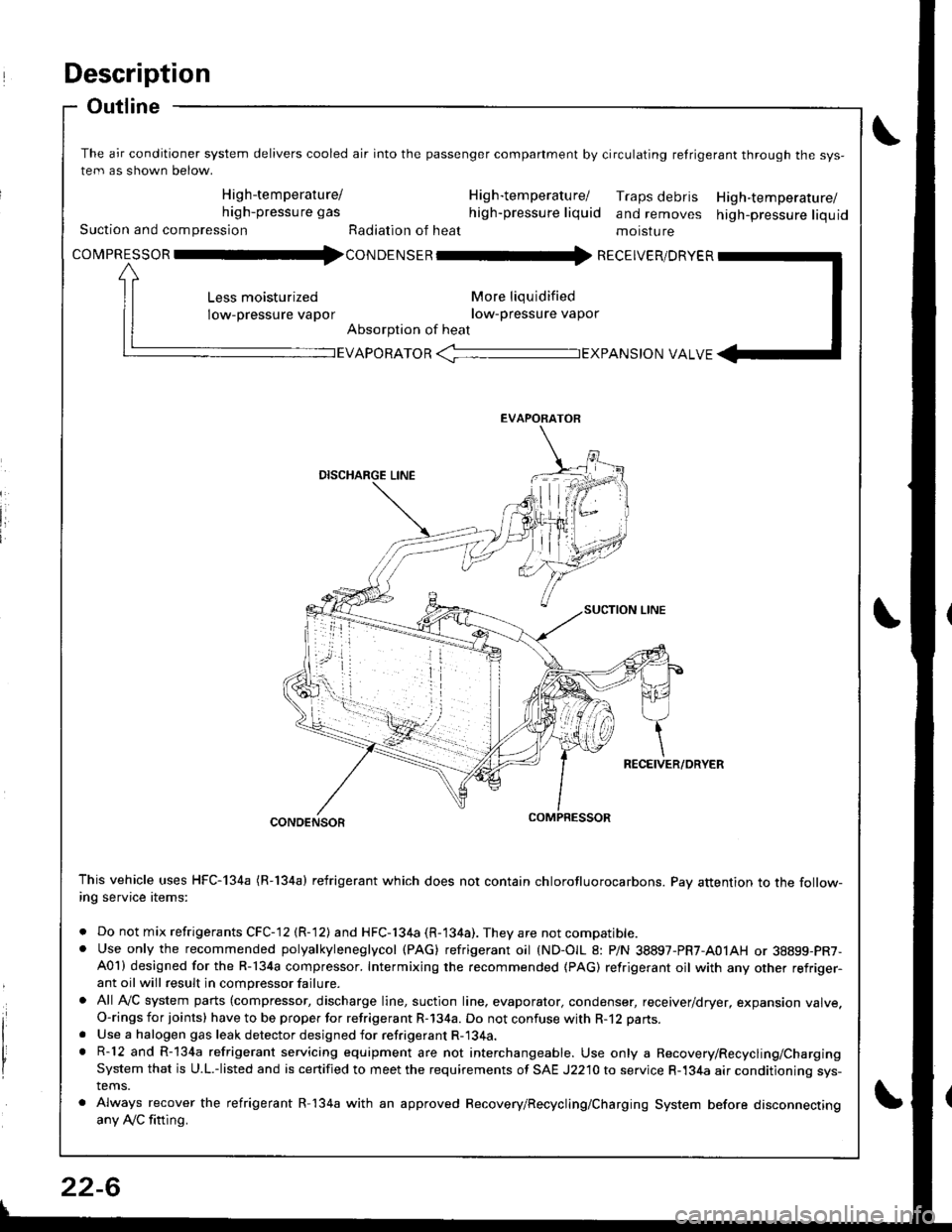
The air conditioner system delivers cooled air into the passenger companment by circulating retrigerant through the sys-
tem as shown below.
High-temperature/ H ig h-tem peratu rel Traps debris High-temperature/high-pressure gas high-pressure liquid and removes high-pressure liquidSuction and compression Radiation of heat moisture
covpnEsson -tl4con oetsen -rr{ REcEIvER/DRvER
More liqu idified
low-pressure vapor
Absorption of heat
Less moisturized
low-pressure vapor
EVAPORATOR -TEXPANS|ON VALVE
EVAPORATOR
CONDENSOR
This vehicle uses HFC-134a (R-134a) refrigerant which does not contain chlorofluorocarbons. Pay attention to the follow-ing service items:
. Do not mix refrigerants CFC-12 (R-12) and HFC-134a (R-134a). They are not compatible.. Use only the recommended polyalkyleneglycol (PAG) refrigerant oil (ND-OIL 8: P/N 38897-PR7-A01AH or 38899-PR7-A01) designed for the R-134a compressor. Intermixing the recommended (PAG) refrigerant oil with any other refriger-ant oil will result in compressor failure.
. All AVC system parts (compressor, discharge line, suction line. evaporator, condenser, receiver/dryer, expansion valve.O-rings for joints) have to be proper for refrigerant R-134a. Do not confuse with R-12 parts.
. Use a halogen gas leak detector designed for refrigerant R-134a.. R-12 and R-134a refrigerant servicing equipment are not interchangeable. Use only a Recovery/Recycling/ChargingSystem that is U.L.-listed and is certified to meet the requirements of SAE J2210 to service R-134a air conditioning sys-tems.
. Always recover the refrigerant R-134a with an approved Recovery/Recycling/Charging System before disconnectingany Ay'C fitting.
22-6
Page 1039 of 1681
A/C Service Tips and Precautions
The air conditioner system uses HFC-134a (R-134a) refrigerant and polyalkyleneglycol {PAG) refrigerant oil (ND-OlL 8: P/N
38897-PR7-A01AH or 38899 - PR7 - A01), which are not compatible with CFC-12 (R-12) refrigerant and mineral oil. Do not
use R-12 refrigerant or mineral oil in this system. and do not attempt to use R-12 servicing equipment; damage to the air
conditioner system or your servicing equipment will result.
Use only service equipment that is U.L.-listed and is certified to meet the requirements of SAE J2210 to remove R-l34a
from the air conditioner system.
CAUTION: Exposure to air conditioner refrigerant and lubricant vapor ot mist can irritate eyos, nose.nd throat, Avoid
breathing th€ air conditionsr rofrigerant 8nd lubricant vapo. or mist.
lf accidental system discharge occurs, ventilate work area before resuming service.
R-134a service equipment or vehicle air conditioner systems should not be pressure tested or leak tested with comp.essed
atf,
@ some mixtures ol air and R-13i[a have been shown to be combustible at olevat6d pre3sures and cln resuh
in fire or explosion causing iniury or property damage. Nover uso compressed air to prossure te3t R-13,[8 service equip-
ment or vehicle air condition6r systems.
Additional health and safety information may be obtained from the refrigerant and lubricant manufacturers,
1. Always disconnect the negative cable from the battery whenever replacing air conditioning parts.
2. Keep moisture and dust out of the system. When disconnecting any lines. plug or cap the Jittings immediately; don't
remove the caps or plugs until just before you reconnect each line.
3. Before connecting any hose or line, apply a few drops of refrigerant oilto the O-ring,
4. When tightening or loosening a fitting, use a second wrench to support the matching fitting.
5. When recovering the system. use a R-134a refrigerant Recovery/Recycling/Charging System; don't release refrigerant
into the atmosphere.
6. Add refrigerant oil after replacing the following parts.
NOTE:
. To avoid contamination, do not return the oil tothe container once dispensed, and never mix itwith other refriger-
ant oils.
.lmmediatelyafterusingtheoil,replacethecaponthecontainerandseal it to avoid moisture absorption.
. Do notspillthe refrigerant oil onthevehicle; it maydamagethe painu itthe refrigerant oil contacts the paint, wash
it off immediately.
Coodansor ..-.-.-............. 25 mt (5/6 ll.oz. 0.9 lmp.oz)
Evaporator ................. ,[0 m/ (1 1/3 fl.oz, 1.4 lmp.ozl
Line or hoss .................. 10 m? {1/3fl.oz, 0.'l lmp.ozl
Receiver/Dryer ............. 10 m/ (1/3 fl.oz, 0.4 lmp.ozl
Leskage repair .............25 m/ {5/6 fl.oZ, 0.9 lmp.oz)
Compreigor .....,......,..Fo1 comprgssor replace-
ment, subtract the volum€ of oil drained from the
removed comprassor lrom l/t{l m[ (1 213 ll.oz, 1,9
imp'ozl, and drain the calculated volume ot oil from
the new compressor: 140 m/ 11 213 ll.oz, 1.9
imp.oz)-Volum€ oI removed comprsssor = Volum€
to drain trom n€w compressor.
NOTE: Even if no oil is drained from the removed
comDressor, don't drain more than 50 m{ {1 2/3
fl.oz. 1.8 lmp.oz) from the new compressor.
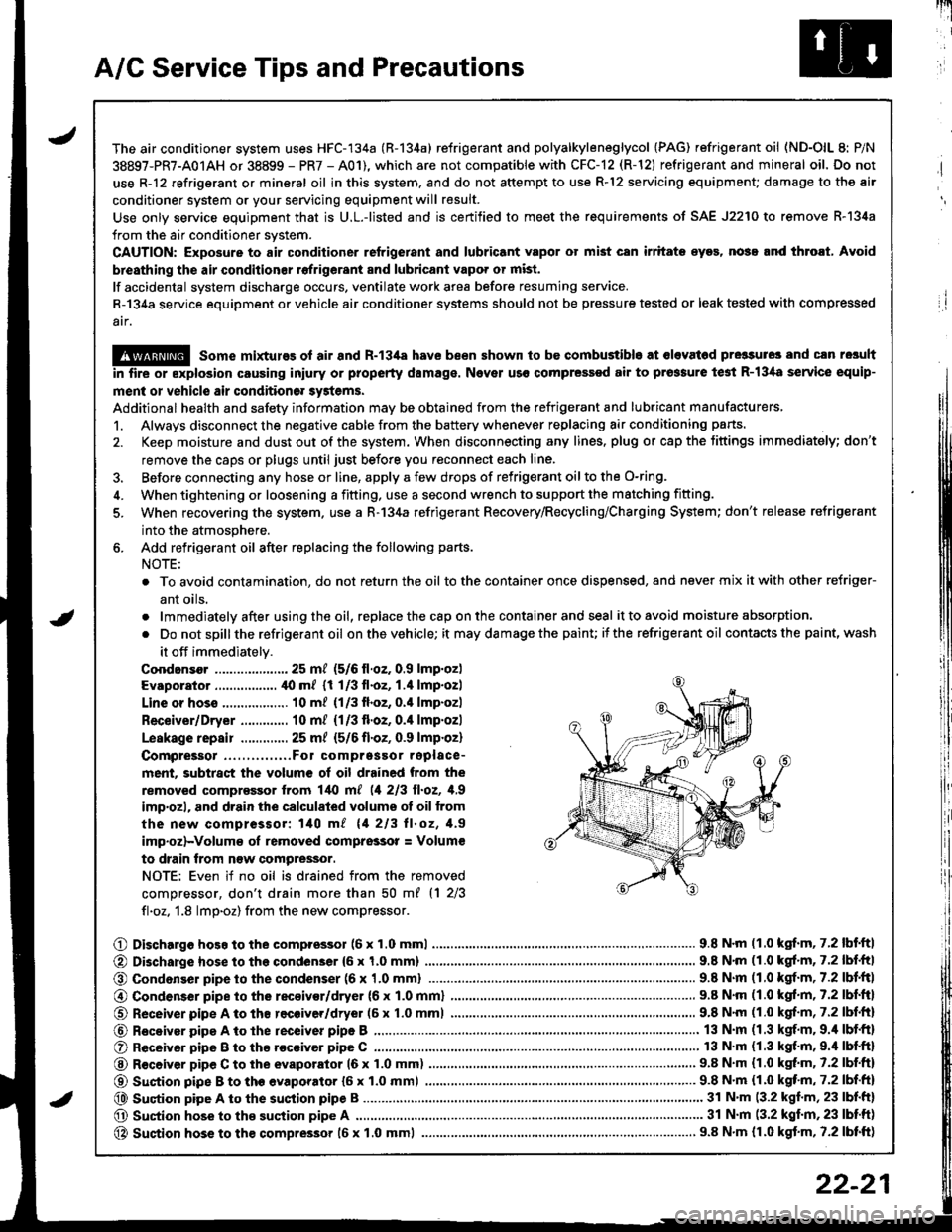
O Dischargo hoso to the compressol (6 x 1.0 mml............................... 9.8 N'm (1.0 kgf.m, 7.2 lbf'ftl
@ Di3charge hose to the condenser {6 x 1,0 mm)
@ Condonser pipe to the condenser (6 x '1.0 mml
9.8 N'm (1.0 kgl.m, 7.2 lbf.ftl
.. 9.8 N.m (1.0 kgf.m,7.2lbl.ltl
@ Condenser pipe to the rec€ivor/dryer (6 x 1.0 mml
O Receiver pipe A to th8 recoiver/dryer (6 x 1.0 mml
@ Receiyar pipe A to lhe receiver pipe B ,...........
O Receiver pipe B to th8 .ocoiver pipe C ............
@ R€ceiver pipe C to the evaporator 16 x 1.0 mm)
@ Suction pipe B to th€ evaporator {6 x 1.0 mm) .......,.
@ Suqtion pipe A to the suction pipe B
O Suction hose to the suction pipe A ...........,.
@ Suction hose to the compressor 16 x 1.0 mml
9.8 N.m (1.0 kgf.m, 7.2 lbf.ftl
9.8 N'm (1.0 kgf.m, 7.2 lbf.fr)
13 N.m (1.3 kgf.m. 9.4 lbf.ft)
13 N.m (1.3 kgf.m,9.'l lbf.ftl
9.8 N.m (1.0 kgt m. 7.2 lbf.ftl
...... 9.8 N.m {1.0 kqf'm, 7.2 lbf.ft)
........ 31 N'm (3.2 kgf.m, 23 lbf.ft)
............ 31 N.m (3.2 kgf.m,23 lbtft)
..................... 9.8 N.m {r.0 kgf.m, 7.2 lbtft)
22-21
Page 1040 of 1681
A/C System Service
Recovery
Use only service equipment that is U.L.-listed and is cer-
tified to meet the requirements of SAE J2210 to remove
HFC-134a (R-134a) from the air conditioner system.
CAUTION: Exposure to air conditioner refrigerant and
lubricant vapor or mist can irritale eyes. nose and
throat. Avoid breathing the air conditioner rclrigerant
and lubricant vapor o. mist.
lf accidental system discharge occurs, ventilate work
area before resuming service.
R-134a service equipment or vehicle air conditioner sys-
tems should not be Dressure tested or leak tested with
compressed air.
@ some mixtures of air and R-134a have
been shown to be combustible at €levated pros3ures
and can result in lire or explosion causing iniury or
plop€rty damage. Never use comprossgd air to pressure
iest R-134a service equipment or vehicle air conditioner
sYstsms.
Additional health and safety information may be
obtained from the refrigerant and lubricant manufac-
tures,
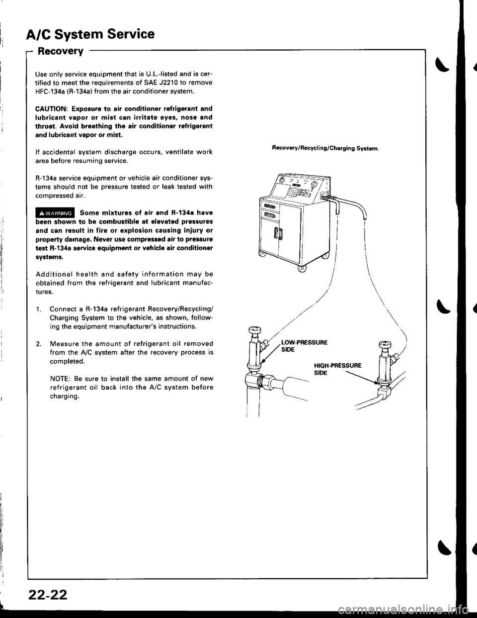
Connect a R-134a refrigerant Recovery/Recycling/
Charging System to the vehicle. as shown, follow-
ing the equipment manufacturer's instructions.
Measure the amount of refrigerant oil removed
from the IVC system after the recovery process is
completed.
NOTE: Be sure to install the same amount of new
refrigerant oil back into the A/C system before
charging.
Recov€ry/Recycling/Cha.ging Systom.
HIGH.PRESSURESIDE
't.
22-22
Page 1042 of 1681
A/C System Service
Performance Test
The performance test will help determine if the air con,
ditioner system is operating within specifications.
Use only service equipment that is U.L.-listed and is cer,
tified to meet the requirements of SAE J2210 to remove
HFC-134a (R-134a) from the air conditioner svstem.
CAUTION: Exposure to air conditioner retrigerant and
lubricant vapor or mist can irritate eyes, nose and
throat. Avoid breathing the air conditioner refrigerant
and lubricant vapor or mist.
lf accidental system discharge occurs, ventilate work
area before resuming service.
R-134a service equipment or vehicle air conditioner sys-
tems should not be pressure tested or leak tested with
compressed arr.
@ some mixtures of air and R-134a have
been shown to be combustible at elevated Dressures
and can result in fire or explosion causing iniury orproperty damage. Never use compressed air to pressure
test R-134a service equipment or vehicle air conditioner
systems.
Additional health and safety information may be
obtained from the refrigerant and lubricant manufactur-
ers.
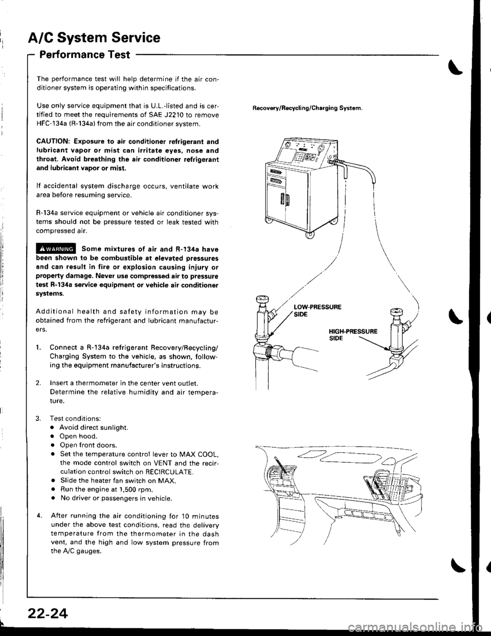
Connect a R-134a refrigerant Recovery/Recycling/
Charging System to the vehicle, as shown, follow-
ing the equipment manufacturer's instructions.
Insen a thermometer in the center vent outlet.
Determine the relative humidity and air tempera-
IUre.
Test conditions:
. Avoid direct sunlight.
. Open hood.
. Open lront doors.
. Set the temperature control lever to MAX COOL,
the mode control switch on VENT and the recir-
culation control switch on RECIRCULATE.. Slide the heater fan switch on MAX.. Run the engine at 1.500 rpm.. No driver or passengers in vehicle.
After running the air conditioning for'10 minutes
under the above test conditions, read the delivery
temperature from the thermometer in the dashvent, and the high and low system pressure from
the A,/C gauges.
Recovo.v/Recycling/Charging System.
LOW.PRESSURE
l
22-24
Page 1047 of 1681
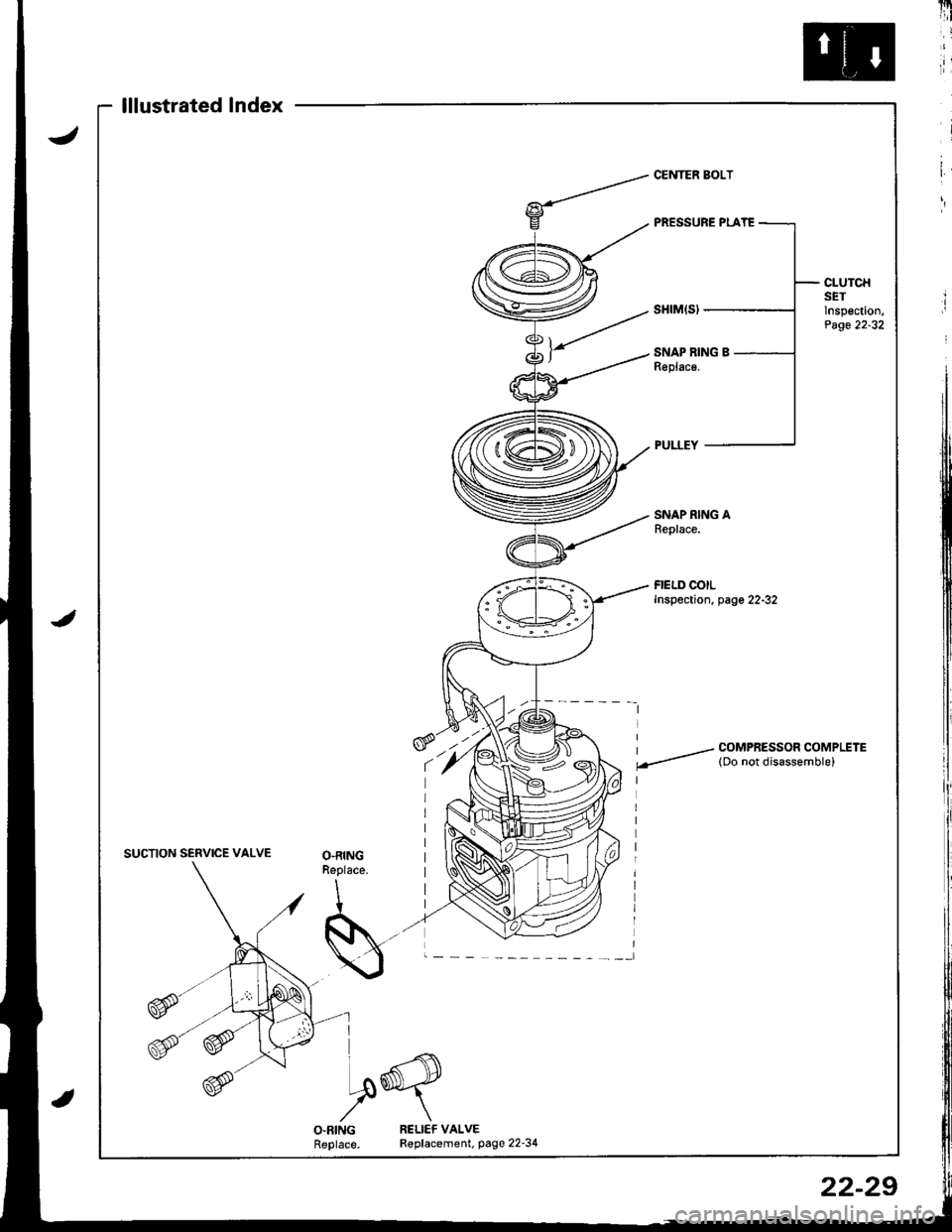
lllustratedlndex
CLUTCHSETlnspection,Page 22-32
SNAP RING AReplace.
FIELD COILInspection, page 22-32
I / COMPRESSOR COMPLETE
.-- lDo not disassemble)
SUCTION SERVICE VALVEO.RINGReplace.
I
S..-
VX
I
I ^.-{\
I.ory
O.RINGReplace.RELICF VALVER€placement. page 22-34
22-29
Page 1049 of 1681
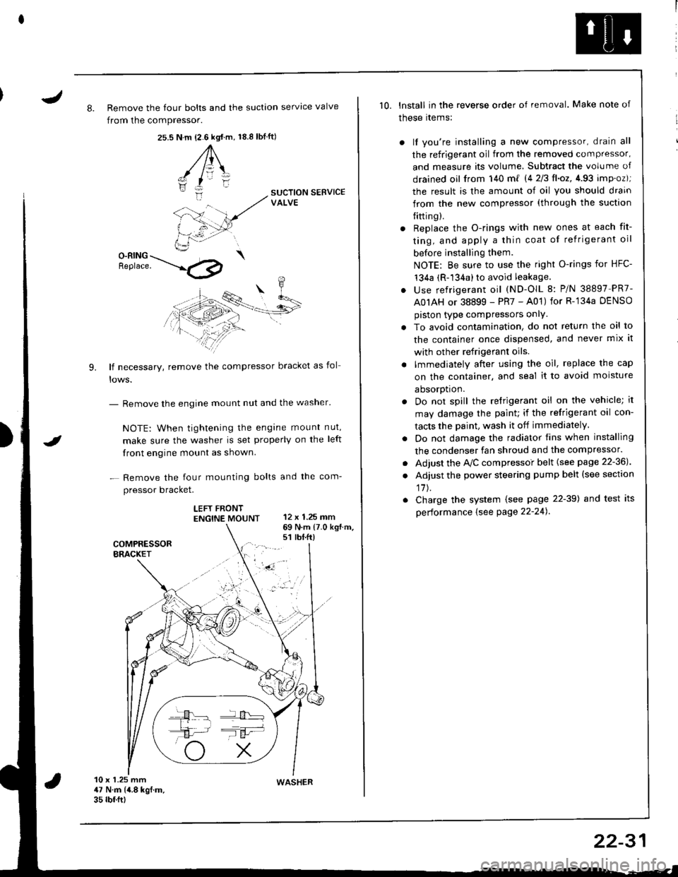
J8. Remove the four bolts and the suction servtce valve
from the compressor.
25.s18.8 tbf.ft)N.m {2.6 kgt.m,
A\
-/ l=\'zI
i:-
9.
SUCTION SERVICEVALVE
O-RING \Benrace. --'.l4p
lf necessary, remove the compressor bracket as fol
- Remove the engine mount nut and the washer'
NOTE: When tightening the engane mount nut,
make sure the washer is set properly on the left
front engine mount as shown.
- Remove the four mounting bolts and the com-
pressor bracket.
LEFT FRONTENGTNE MOUNT 12 x 1.25 mm
I
69 N.m {7.0 kg{.m.s1 rbt.ft)
10 x 1.25 mm47 N.m (4.8 kgf.m.35 rbf.ftt
10. lnstall in the reverse order of removal. Make note of
these rtems:
) lf you're installing a new compressor, drain all
the refrigerant oil from the removed compressor,
and measure its volume, Subtract the volume of
drained oil from 140 m{ 14 2/3ll.oz,4.93 imp.oz);
the result is the amount of oil you should drain
from the new compressor (through the suction
{itting).
r Replace the O-rings with new ones at each fit-
ting, and apply a thin coat of refrigerant oil
before installing them.
NOTE: Be sure to use the right O-rings for HFC-'t34a (R-134a) to avoid leakage.
. use refrigerant oil (ND-OlL 8: P/N 38897 PR7-
A0IAH or 38899 - PR7 - A01) for R-'134a DENSO
piston type compressors onlY.
. To avoid contamination, do not return the oil to
the container once dispensed, and never mix it
with other refrigerant oils.
. lmmediately after using the oil, replace the cap
on the container, and seal it to avoid moisture
aDsorDt|on.
. Do not spill the refrigerant oil on the vehicle; it
may damage the paint; if the refrigerant oil con-
tacts the Daint, wash it off immediately.
. Do not damage the radiator fins when installing
the condenser fan shroud and the compressor.
. Adjust the Ay'C compressoi belt {see page 22-36J
. Adjust the power steering pump belt (see section
17J.
. Charge the system (see page 22-39) and test its
performance {see Page 22-24).
WASHER
22-31