service HONDA INTEGRA 1998 4.G Workshop Manual
[x] Cancel search | Manufacturer: HONDA, Model Year: 1998, Model line: INTEGRA, Model: HONDA INTEGRA 1998 4.GPages: 1681, PDF Size: 54.22 MB
Page 1355 of 1681
)
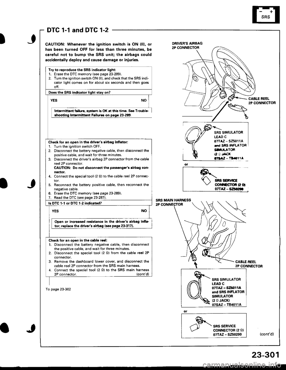
DTC 1-1 and DTC 1-2
CAUTION: Whenever the ignition switch is ON {lll, or
has been turned OFF for less thsn three minutes, be
ca.eful not to bump the SRS unit; the airbags could
accidentally deploy and cause damage or iniuries.
CABLE REEL2P CONNECTOR
SRS SIMULATORL€AD CoTtaz - s6011Alrd Sns IYFLATORg.prToR
o ! Jrcxatllil - n olrl
*.t sns savE\,' colltcroe c o07TAZ-8E@
CABLE BEEL2P CONNECTOR
SRS SERVICEGoNNECTOR (2 0l
07TAZ - 5250200(cont'd)
Try to roproduce the SRS indicator light:1. Erase the DTC memory lsee page 23-289).2. Turn the ignition switch ON (ll), and check that the SRS indicator light comes on tor about six seconds and then goes
ofJ.
Do€s the SRS indicator light stay on?
YES
h6rmittar'rt Lalul!, 3yrtdll b o|( rt thb tiiru. 5€6 lroubl6-ahootino lmarmitlant Failura. on o.oa 23-289.
Chock fo. an opGn in the dlivgl's cirbag infirtor:'1. Turn the ignition switch OFF.2. Disconnect the battery negative cable, then disconnect thepositive cable, and wail for thrce minutes.3. Disconnect the driver's airbag 2P connectorlrom th€ cablereel 2P connector-CAUTION: Do not disconnoct tho palF€nger'r .ilb.g con-nector.4. Connect the sDecial tool 12 o) to the cable reel 2P connec-tor.5. Reconnect the bsftery positive cable, then reconn€ct thonegative cable.6. Erase the DTC memory (se€ page 23-289).7. Bead the DTC (see page 23-2811.
ls DTC 1-1 oI DTC 1-2 indic.tod?
YESNO
Opon or incro8od r.rist.nco in tho driv6.'3 airbag inf+
lor; replacs tho drivor'3 rirb.g lsoe prgg 23-317).
Ch.ck for an op6n in the cablo re.l:1. Disconnect the battery negativo cabl6, thon disconnectthe positive cable, and wait for three minutes.2. Disconnect the soecial tool (2 o) from rhe cable reel 2Pconnector.3. Remove the dashboard lower cover. and disconnoct thecable reel2P connectorfrom the SRS main harness.4. Connect tho special tool (2 0) to thg SRS main harness2P connector. (cont'dl
To page 23-302
SRS SIMULATOR|.EAO C07TAZ - Si4tor lAand SRS INFLATORSIMULATOR(2 0 JACK)
23-301
Page 1359 of 1681
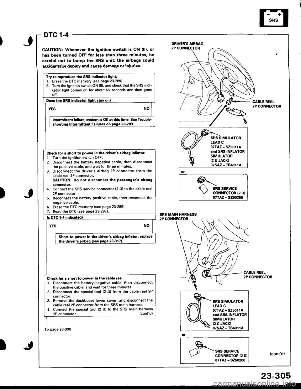
DTC 1-4
GAUTION: Whenever the ignition ewitch i! ON (ll), or
has been turned OFF tor l€ss than ihre€ minutes, be
caroful not to bump the SRS unit; tho airbag3 could
accidrnta[y deploy and caus€ damage or iniuries.
9--'-.- sns sERvrcE\,/ cli|f\FgfoR {2 ol07TAZ - SZqI200
ol
SRS SERVICEcot{ltEcToR {2 0}07TAZ - S:Zso2qt
CABLE REEL2P CONNECTOR
(cont'd)
Try to r.p.oduco tho SRS indicator light:1. Erase the DTC memory (see page 23-289).2. Turn the ignition switch ON (ll), and check that the SRS indi-
cator light comes on lor about six seconds and then goes
off.
Doo3tho SBS indic.tor light stry on?
YESNO
lnt rmittont tsiluio, systom i! (X tt thb timc. Soo Troublc
shooting Inte.mittani Failutca on P.g. 23-289.
Chock tor a shortto power in tha drivo/! ritbag inflllor:
l. Turn the ignition switch OFF.2. Disconnect the battery negativ€ cable, then disconnsct
th6 oositive cable, and wait for three minutes.
3. Disconn€ct the driver's airbtg 2P connector from the
cable reel 2P conn6ctor.CAUTION: Do not disconnost tha p!r3ong.t's rirbag
connoclor.4. Connect the SRS service connector (2 O) to the cable reel
2P connector,5. Reconnect the battery positive cable, then reconnect thenegative cabl€.6. Erase the DTC memory lsee page 23-289).7. Read the DTC (see gage 23-2aiL
|3 DTC 1-4 indicrtod?
YESNO
Shon to powa. in tha d val's tiabag itlflltor; iopl.cathe ddv.r'. airbag {t€c prge 23-317).
Check for ! short to pow.r in the cabls.oali1. Disconnect the battery negative cable. then disconnectthe positive cable, and wait for three minutes.2. Disconnect th€ special tool (2 o) from the cable reel 2P
conneclor.3. Remove the dashboard lower cover, and disconnect the
cable reel 2P connector from the SRS main harness./t. Connect the special tool (2 o) to tha SRS main harness
2P connector. (cont'd)
To page 23-306
)
,\fr)d
cffi
SRS SIMULATORLEAD C07TAZ - SZ5011Arnd SRS INFLATORSIMULATORt2 0 JACKI07SAz - TBil011A
23-305
Page 1361 of 1681
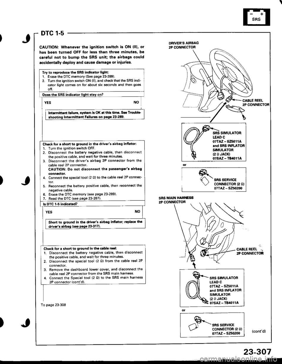
DTC 1-5
CAUTION: Whenever thc ignition switch i3 ON (lll, ot
has been turned OFF for less than throe minutss, bo
caretul not to bump the SRS unit; the airbsgs could
accidcntally deploy and cause damage or iniuri6.
DRIVER'S AIRBAG2P CONNECTOR
\"o""'"o'
CABI.E REEL
{cont'd}
)SRS SERVICECoNNECTOR 12 0)07TA2 - S250200
';
CABLEREEL.,2P OONNECTOF
)
ol
SRS SERVICECoNNECTOR (2 0l
07TAZ - SZSo2(xt
Try to ..produco the SRS indicator light:1. Erase the DTC memory (See page 23-289).2. Torn the ignition switch ON (ll), and chockrhattho SRS indi-cator light comes on for about six seconds and then goes
off.
Ooes ihe SRS indicator lighl slay on?
rffit
i .hooting ldt.rnittont Frilul.. on p.g. 23-289. I
Chock to. a 3hort to glound in tho drivor's airbag inflato.:
1. Turn the ignition switch OFF.2. Disconnect the battery nggative cable, then disconnect
the oositive cable, and wait forth.oe minutes.
3. Disconnect the driver's airbag 2P connoctor from the
cable reel 2P connector.CAUTION: Do not disconnsct tha pt!3onga]'t rirbrg
connoctor.4. Connect the special tool (2 0) to tho cable reel 2P connec_
tor,5. Reconnect tho battery positive cablo, then reconnoct the
negativ€ cable.6. Erase the DTC memory (see page 23-289)
7. Read the DTC (see pag623-2871.
k DTC 1-5 indicated?
YESNO
Sho.t to gtound in tha drive/s ri6ag infi.tor; ruplaco tho
drivor'3 .irbss (s.o p.g€ 23-3171.
Ch.ck tor a 3ho.t to gtound in tha cable ?ral:
1. Disconnect the battery negative cable. then disconnect
the oositive cable, and wait for three minutes.
2. oisconnect the special tool (2 0) lrom the cable reel 2P
connector,3. Remove the dashboard low€r cove., and disconnecl thg
cable reel 2P connector lrom the SRS main harn6ss,1. Connect the Special tool (2 0) to the SRS main harness
2P connoctor lcont'd).
To page 23-308
07TAZ - SZ50t1A.nd SRS INFLATORSIMULATOR{2 0 JACK}07SAZ - TB/OI lA
SRS SIMULATORLEAD C07TAZ - SZ501rAand SRS INFLATORSIMULATOR(2 0 JACKI07SM - TBi|t}l1A
23-307
Page 1367 of 1681
\
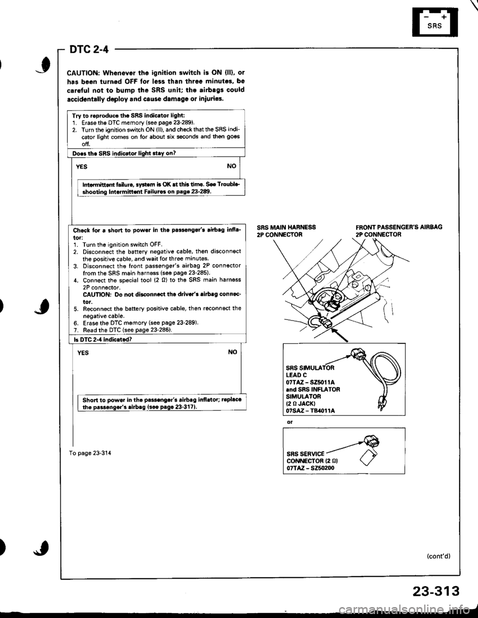
DTC 2-4
CAUTION: Whenevor th6 ignition switch is ON (ll), or
has been turned OFF for less than threo minutcs, be
car€ful not to bump lhe SRS unit; the airbEgs could
accidontslly dcploy and cause damag€ 01 iniuries.
SRS MAIN HABNESS2P CONNECTORFRONT PASSENGER'S AIRBAG
2P CONNECTOR
ot
SBS SERVICEcoNNECTOR {2 0l07TAZ - SZ5o200
(cont'd)
23-313
_-t
)
Try to roproduce th. SRS indicrtor lighl:1. Erase the DTC memory (see page 23-289).2. Turn the ignition switch ON (ll), and chock that the SRS indi-
cator light comes on for about six seconds and then goes
off.
Do.3 th. SRS indicator lighi stay on?
NOYES
Ini.rmitt.nt t iluro, !y*em b OK .t thb timo. Soe Ttoubl+,
shooting lmormittent Failuraa on P.ge 23.289
Ch6ck tor a 3hon to powol in tha pa3tonga/t lirbag infla_
to.:1. Turn the ignition switch OFF.2. Disconnect the battory negative cable, then disconnect
the oositive cable, and wait tor three manutes
3. Disconnect the front passenger's airbag 2P conn€ctorIrom the SRS main harnoss (see page 23-285).
4. Connect the soecial tool (2 0) to the SRS main harness
2P connector.CAUTION: Do not dilconn.ct tho driv.l'! .irb.g conn.c'
tor.5. Reconnect the battery positive cable, then reconnoct the
negative cable.6. Erase the DTC memory (see page 23-289).7. Read the DTC (see page 23-2861.
b DTC 2-4 indicatcd?
YESNO
Short to powor in th. pa$anoar'3 airbrg infldtor; tepl&t
the Dass6nqor'3 .irbaq {sco prgc 23-3171
To page 23-314
07TAZ-SZ50t1A.nd SRS INFLATORSIMULA'OR(2 0 JACKT07sAz - TB()11A
Page 1369 of 1681
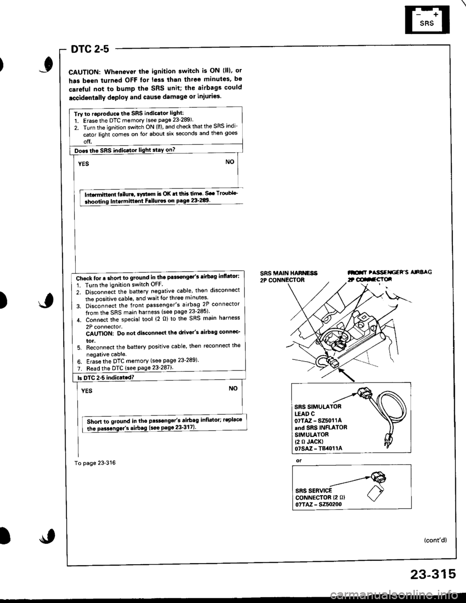
DTC 2-5
CAUTION: Whenever the ignition switch is ON (lll. ot
has been turned OFF lor less than thlee minules. be
careful not to bump the SRS unit; th€ airbags could
accidentally deploy and cause damage 01 injuri€s.
lnta.mittor tailure, aFtcrn b OK st ihb ti.rF. Sa. Tto.tbl''_
Intermittont FriluJor on pag€ 2&289.
SRS MAIN HARNESA2P CONNECTORml tlssfrliaFs AnSaG
)
u---
or
SRS SERVICECoNNECTOR {2 0lo?TM - 5250200
(cont'd)
Try to roproduce tho SRS indic.tor light:
1. Erase the DTC memory (see page 23-289).
2. Turn the ignition sv/itch ON (ll). and check that the SRS indi-
cator light comes on for about six seconds and then goes
off.
Doo6 tho SRS indic.tor light stay on?
Chgck tor a short to ground in the Pa*t€ngd'3 tirbag inflttor:
1. Tlrn the ignition switch OFF
2. Disconnect the battery negative cable, then disconnect
the oositive cable. and wait for thr€6 minutes
3. Dis;onnect the front passenger's airbag 2P connector
from the SRS main harness (see page 23-285)'
4. Connoct the special tool (2 o) to the SRS main harness
2P connector.CAUTION: Do not disconngd tho drivo"s airbtg connoc'
tor.5. Reconnect the battery positive cable' then reconnect the
negalive cable.
6. Eras6 the DTC memory (see page 23-289)'
7. Fead the DTC {see page 23'287l'.
Short to ground in tho pts.range/s airbag inflator; rsplac€
tho Da3sonse/3 si.bag (sao
23-315
Page 1375 of 1681
)6.
7.
8.
Connect a 12 volt battery to the tool:
. lf the green light on the tool comes on, the alr-
bag igniter circuit is defective and cannot deploy
the airbag. Go to Damaged Airbag Specia I
Procedure.
. lfthe red light on the tool comes on, the airbag is
ready to be deployed.
Push the tool's deployment switch The airbag
should deploy (deployment is both highly audible
and visible; a loud noise and rapid inflation of the
bag, followed by slow deflation).
. lf the airbags deploy and the green light on the
tool comes on, continue with this procedure
. lf an airbag doesn't deploy. yet the green light
comes ON, its igniter is defective. Go to Dam-
aged Airbag Special Procedure.
!!@ During deployment, the airbag c8n
become hot enough to burn you Wait thirtY min-
ut€s after d€ployment befote touching the assem-
blv.
Dispose of the complete airbag. No part of it can be
reused. Place it in a sturdy plastic bag, and seal it
securery.
CAUTION:
. wear a lace shield and gloves when handling a
deployed airbag.
. Wash your hands and rinse them well with
water after handling a deployed sirbag
)
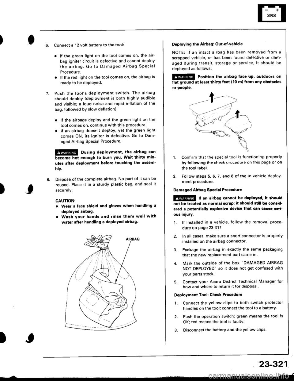
Deploying the Airbag: Out-ot-vehicle
NOTE: lf an intact airbag has been removed from a
scraDDed vehicle, or has been found defective or dam-
aged during transit, storage or service, it should be
deoloved as follows:
@@ Position th€ airbag laca up. outdoors on
tlat ground at l€ast thirty leet (10 m) ftom any obstacles
or people.
1. Confirm that the special tool is functioning properly
by tollowing the check procedure on thls page or on
the tool lab€|.
2. Follow steps 5, 6, 7, and 8 ol the in.vehicle deploy'
ment orocedure.
Damaged Airbag Sp€citl Procedurc
!@ [ an airbag cannot be d.ploytd, h 3hoold
not be lreated as normal scrap; it should 3till b. corlrkl
ered a polentially sxplosive device that can clura tari
ous iniury.
1. lf installed in a vehicle, follow the removal proce-
dure on page 23-317.
2. ln all cases, make sure a short connector is properly
installed on the airbag connector.
3. Package the airbag in exactly the same packaging
that the new replacement part came In.
4. Mark the outside of the box "DAMAGED AIRBAG
NOT DEPLOYED" so it does not get confused with
your Parts stock.
5. Contact your Acura District Technical lvanager for
how and where to return it for disposal.
Deployment Tool: Ch€ck Ptocedure
1. Connect the yellow clips to both switch protector
handles on the tool; connect the tool to a battery
2. Push the operation switch: green means the tool is
OK; red means the tool is faultv.
3. Disconnect the battery and the yellow clips
23-321
Page 1380 of 1681
SRS Unit
Replacement
CAUNON:
. Betore disconnecting the SRS main harness 18P con-
nector, disconnect the aitbag connectors.
. During installation or replacement, do not bump
(impact wrench, hammer etc.) the al€a near the SRS
unit.
. Do not damage the SRS unit terminals or connec-
tors.
. Do not disassemble the SRS unit; it has no service-
able parts.
. Store the SRS unit in a clean, dry area.
. Do not use any SRS unit which has been subiected
to water damage or shows signs of being dtopped ol
improperly hsndled, such as dents, cracks or detor-
mation.
Disconnect the baftery negative cable, then discon-
nect the positive cable from the battery, and wait at
least three minutes.
Disconnect the airbag connectors. (When discon-
nected. the airbag connectors are automatically
shorted.)
Driver's Side:
. Remove the access panel from the steering
wheel, then disconnect the 2P connector
between the driver's airbag and cable reel (see
page 23-285).
Front Passenger's Side:
. Disconnect the 2P connector between the front
passenger's airbag and SRS main harness (see
page 23-285).
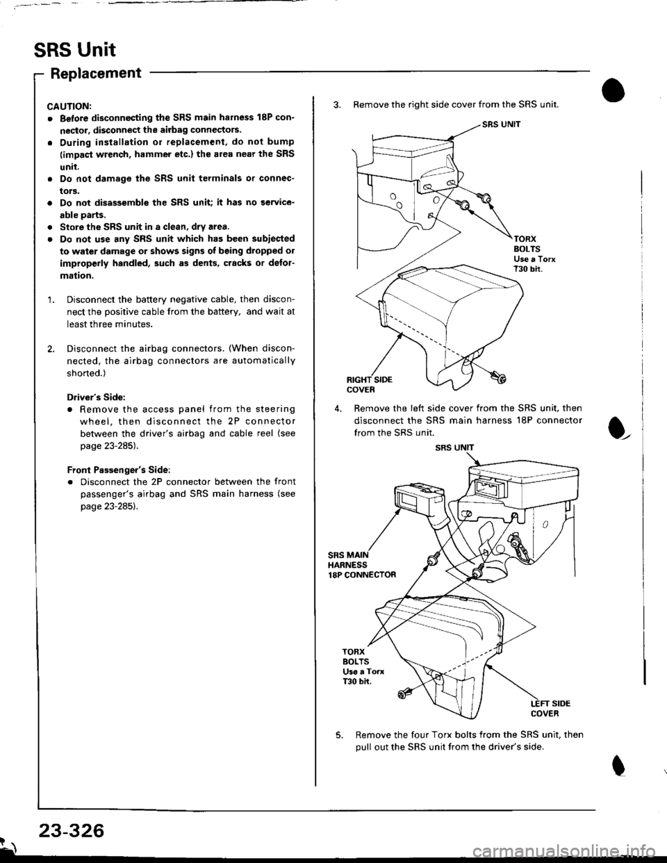
3. Remove the right side cover from the SRS unit.
SRS UNIT
TORXBOLTSUse a TorxT30 bir.
SIDEcovEn
4. Remove the left side cover from the SRS unit, then
disconnect the SRS main harness 18P connector
from the SRS unit.
sRsHARNESS18P CONNECTOR
t
TORXBOLTSU36 a ToaxT30 bh.
SIDECOVER
Remove the four Torx bolts from the SRS unit, then
pull out the SRS unit from the driver's side.
23-326?\
SRS UNIT
Page 1383 of 1681
).1
Contents
How to Use This l\.4anual 1Circuit Schematics (see Circuit Index)Fuse/Relaylnformation 6ComponentLocation Photographs 201
Connector Cavity Numbers 202Connectorldentification 203
Ground-to-Components Index 6-6Wire Harness Routing 203Circuit ldentification lor ln-Line and Fuse Box Connectors
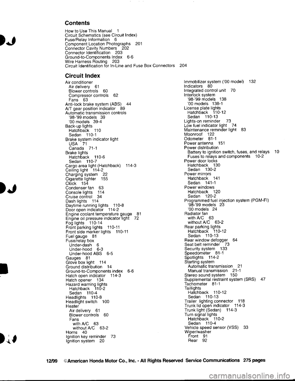
Circuit Index
Air conditionerAir delivery 61Blower controls 60Compressor controls 62Fans 63Anti-lock brake system (ABS) 44A/T gear position indicator 89Automatic transmission controls'98199 models 39'00 models 39-4Back-up lightsHatchback 110Sedan 110- 1Brake system indicator light
USA 71Canada 71-1Brake lightsHatchback 110-6Sedan 110-7Cargo area light (Hatchback) 114-3Ceiling light 114-2Charging system 22Cigarette lighter 155
Clock 154Condenser fan 63Console lights 114Cruise control 34Dash lights 1 14Daytime running lights 110-8Door open indicator 114-2Engine coolant temperature gauge 81Engine oil pressure indicator light 72Fog lights 110-14Front parking lights 110-11Front side marker lights 110-11Fuel gauge 81Fuse/relay boxUnder-dash 6Under-hood 6-3Under-hood ABS 6-5Gauges 81Glove box light 114Ground distribution 14Ground-to-Componentsindex 6-6Hatch open indicator '114-3
Hatch opener '134
Hazard warning lightsHatchback 'l l0-2Sedan 110-4Headlights 1'10-8Headlight switch 100HeaterAir delivery 61Blower controls 60Fanswith A,/C 63without A,/C 63-2Horns 40lgnilion key reminder 73lgnition system 20
204
lmmobilizer system ('00 model) 132lndicators 80Integrated control unit 70Interlock system'98199 models 138'00 models 138-1License plate lightsHatchback 110-12Sedan 110-13Lights-on reminder 73Low fuel indicator light 74l\,4aintenance reminder light 83l\iloonroof 122Odometer 81-1Power antenna 151Power distributionBattery to ignilion switch, fuses, and relays
Fuses to relays and components 10-2Power door locksHatchback '130
Sedan 130-2Power mirrorsHatchback 141Sedan 141-1Power windowsHatchback 120Sedan 120-2Programmed fuel injection system (PGM-Fl)'98199 models 23'00 models 24Radiator fanwith tuC 63without A,/C 63-2Rear parking lightsHatchback 110-12Sedan 110- 13Rear window defogger 64Seat belt reminder 73Security system 133Speedometer Il-1Spotlights 114-2Starting syslemAutomalictransmission 21l\.4anualtransmission 21-1Stereo sound system 150Supplemental restraint system (SRS) 47Tachometer 81- 1TaillightsHatchback 110-12Sedan 110-13Trailer lighting conneclor 118Trunk lid open indicator 114-3Trunk light (Sedan) 114-3Turn signal lightsHatchback 110-2Sedan 110-4Vehicle speed sensor (VSS) 33Wiper/washerFront 91Rear 92
10
).1
I
Xr
12Fg oAmerican Honda Motor Co., Inc. - All Rights Reserved Service Communications 275 pages
Page 1395 of 1681
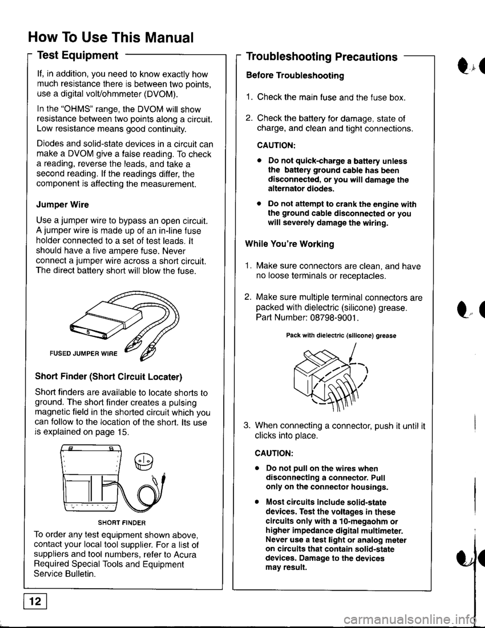
How To Use This Manual
Test Equipment
lf, in addition, you need to know exactly how
much resistance there is between two ooints.
use a digital volVohmmeter (DVOM).
In the "oHMS" range, the DVOM will show
resistance between two points along a circuit.
Low resistance means good continuity.
Diodes and solid-state devices in a circuit can
make a DVOM give a false reading. To check
a reading, reverse the leads, and take a
second reading. lf the readings differ, the
component is affecting the measurement.
Jumper Wire
Use a jumper wire to bypass an open circuit.
A jumper wire is made up of an in-line f use
holder connected to a set of test leads. lt
should have a tive ampere fuse. Never
connect a jumper wire across a short circuit.
The direct battery short will blow the fuse.
Short Finder (Short Circuit Locater)
Shoft linders are available to locate shorts to
ground. The short finder creates a pulsing
magnetic field in the shorted circuit which you
can follow to the location of the short. lts use
is explained on page 15.
SHORT FINDER
To order any test equipment shown above,
contact your local tool supplier. For a list of
suppliers and tool numbers, refer to Acura
Required Special Tools and Equipment
Service Bulletin.
Troubleshooting Precautions
Before Troubleshooting
1. Check the main fuse and the fuse box.
2. Check the battery for damage. state of
charge, and clean and tight connections.
CAUTION:
. Do not quick-charge a battery unless
the battery ground cable has been
disconnected, or you will damage the
alternator diodes.
. Do not attempt to crank the engine with
the ground cable disconnected or you
will severely damage the wiring.
While You're Working
1. Make sure connectors are clean, and have
no loose terminals or receotacles.
2. Make sure multiple terminal connectors are
packed with dielectric (silicone) grease.
Part Number: 08798-9001 .
Pack with dielectric (silicone) grease
When connecting a connector, push it until it
clicks into olace.
Do not pull on the wires when
disconnecting a connector. Pull
only on the connector housings.
Most circuits include solid-state
devices. Test the voltages in these
circuits only with a 1o-megaohm or
higher impedance digital multimeter.
Never use a test light or analog meter
on circuits that contain solid-state
devices. Damage to the devices
may result.
Qr(
l"(
Page 1406 of 1681
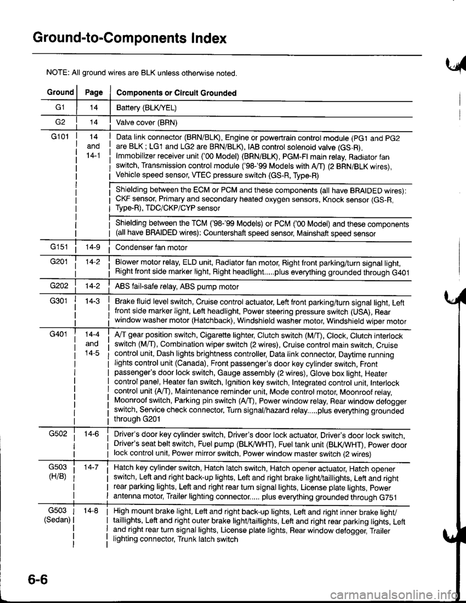
Ground-to-Components I ndex
NOTE: All ground wires are BLK unless otherwise noted.
GroundPageComponents or Circuit Grounded
Battery (BLIVYEL)
--t'I Valve cover (BRN)
G101t.+
and
14-1
Daia link connector (BRN/BLK), Engine or powertrain controt module (pct and pG2
are BLK; LG1 and LG2 are BRN/BLR, IAB controt solenoid valve (GS-B),
lmmobilizer receiver unit ('00 Model) (BRN/BLR, PGM-Ft main retay, Radiator fan
switch, Transmission control module ('98.�99 Models with MD (2 BRN/BLK wires),
Vehicle speed sensor, WEC pressure switch (GS-R, Type-R)
Shielding between the ECM or PCM and these components (all have BRAIDED wires):
CKF sensor, Primary and secondary heated oxygen sensors, Knock sensor (GS-R,
Type-R), TDC/CKP/CYP sensor
Shielding between the TCM ('98-'99 Models) or PCM ('00 Model) and these components(all have BRAIDED wires): Countershaft speed sensor, Mainshaft speed sensor
G1s1 ii Condenser fan motor
Brake fluid level switch, Cruise control actuator, Left front parking/turn signal light, Left
front side marker light, Left headlight, Power steering pressure switch (USA), Rear
window washer motor (Hatchback), Windshield washer motor, Windshield wiper motor
14-3
Blower motor relay, ELD unit, Badiator fan motor, Right front parking/turn signal light,
Right front side marker light, Right headlight.....plus everything grounded through G401
ABS fail-safe relay, ABS pump motor
G40114-4
ano
l4-c
A,/T gear position switch, Cigarette lighter, Clutch switch (M,/T), Ctock, Ctutch interlock
switch (MfD, Combination wiper switch (2 wires), Cruise control main switch, Cruise
control unit, Dash lights brightness controller, Data link connector, Daytime running
lights control unit (Canada), Front passenger's door key cylinder switch, Frontpassenger's door lock switch, Gauge assembly (2 wires), Glove box light, Heater
control panel, Heater tan switch, lgnition key switch, Integrated control unit, Interlock
control unit (AfI), Maintenance reminder unit, Mode control motor, Moonroof relay,
Moonroof switch, Parking pin switch (AfD, Power window relay, Rear window defogger
switch, Service check connector, Turn signal/hazard relay.....plus everything grounded
throuoh G201
Driver's door key cylinder switch, Driver's door lock actuator, Drivels door lock switch,Driver's seat belt switch, Fuel pump (BLI(/WHT), Fuel tank unit (BLI(/WHT), power doorlock control unit, Power mirror switch, Power window master switch (2 wires)
Hatch key cylinder switch, Hatch latch switch, Hatch opener actuator, Hatch ooener
switch, Left and right back-up lights, Left and right brake light/taillights, Lett and right
rear parking lights, Left and right rear turn signal lights, License plate lights, power
antenna motor, Trailer lighting connector..... plus everything grounded through G751
6-6
'14-8G503
(Sedan)
High mount brake light, Left and right back-up lights, Lett and right inner brake tighv
taillights, Left and right outer brake light/taittights, Left and right rear parking tights, Leftand right rear turn signal lights, License plate lights, Rear window detogger, Trailer
lighting connector, Trunk latch switch