service HONDA INTEGRA 1998 4.G Manual PDF
[x] Cancel search | Manufacturer: HONDA, Model Year: 1998, Model line: INTEGRA, Model: HONDA INTEGRA 1998 4.GPages: 1681, PDF Size: 54.22 MB
Page 772 of 1681
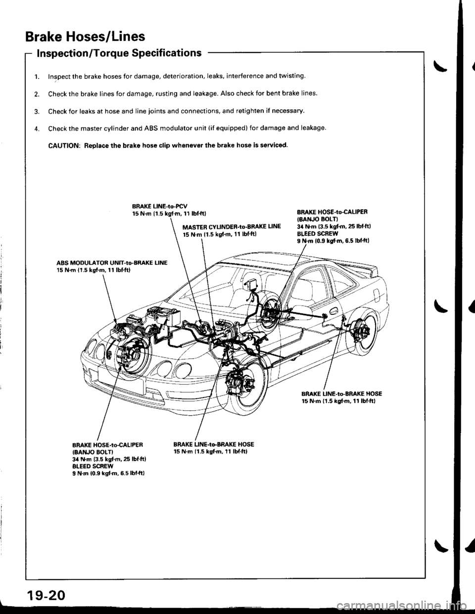
Brake Hoses/Lines
Inspection/Torque Specif icationsInspecuon/ | orque Dpecl carlon
1. Inspect the brake hoses for damage, deterioration, leaks, interference and twisting
2. Check the brake lines for damage, rusting and leakage. Also check tor bent brake lines.
3. Check ior leaks at hose and line joints and connections, and retighten if necessary.
4. Check the master cylinder and ABS modulator unit (if equipped) for damage and leakage.
CAUTION: Replace the braks hose clip whenever the brake hose is serviced.
15 N.m 11.511 tbl.f0
MASTER CYLINDER'Io'BBAKE UNE
15 N.m {1.5 kgt'm, 11 lbf ft}
BnAKE HOSE-Io-CALIPER
IMNJO BOLTI3a N'm 13.5 kgf.m. 25 lbl ft)
BLEED SCREWI N.m 10.9 ks{.m,6.5 lbf.ftl
ABS MODULATOR UNIT-Io-BRAKE LINE15 N.m (1.5 kg{.m, 11 lbtftl
BRAKE LINE-Io-BRAKE HOSE15 N'm lt.5 kgf.m, 11 lbf.ftl
BnAKE HOSE-Io-CALIPER
IBAruO BOLTI3il N.m (3.5 kgt m, 25 lbf.ft)ALEED SCREWI N'm 10.9 kgtm,6.5lbf.ftl
BRAKE LINE-Io-BRAKE HOSE15 N.m 11.5 kgfm, 11 lbf.ftl
BMKE LINE-Io-FCV
l
It
I
i
i
i
Page 783 of 1681
![HONDA INTEGRA 1998 4.G Manual PDF SEFVCECfiEC{CONMCIOF (2P)
Ecgq f too..,I dinFD OITA LrNiLTILU i -- CoNr€CToF Lr6P)8LU!Lsru-6J;:--l
8AN/OJ( ltx
44cli1 c2o]_crol
IIHEEI SENSOf,-------61,^r
,--Ej.*
ABS CONTROL UNIT22P CONNECTOR{O HONDA INTEGRA 1998 4.G Manual PDF SEFVCECfiEC{CONMCIOF (2P)
Ecgq f too..,I dinFD OITA LrNiLTILU i -- CoNr€CToF Lr6P)8LU!Lsru-6J;:--l
8AN/OJ( ltx
44cli1 c2o]_crol
IIHEEI SENSOf,-------61,^r
,--Ej.*
ABS CONTROL UNIT22P CONNECTOR{O](/img/13/6069/w960_6069-782.png)
SEFVCECfiEC{CONMCIOF (2P)
Ecgq f to'o..,I dinFD OITA LrNiLTILU i -- CoNr€CToF Lr6P)8LU!L'sru-6J;:--l
8AN/OJ( ltx
44c'li1 c2o]_crol
IIHEEI SENSOf,-------61',^r
,--Ej.*
ABS CONTROL UNIT22P CONNECTOR{O numbedWHEEL SENSONCONNECTOR
FRONTJEIL.rGT;-r\
REAR
lr 2l
SERVICE CHECKCONNECTOR (2P)
1t 1l
ABS CONTROL UNIT 12P CONNECTOR(l number)n t=l
lr 2 3l4ls 6l
lrl Bl;iiltilld
618910tl
t2'14161llt9202122
DATA LINK CONN€CTOR{16P)
121315
19-31
Wire sids ot lemale tsrminals
Page 785 of 1681
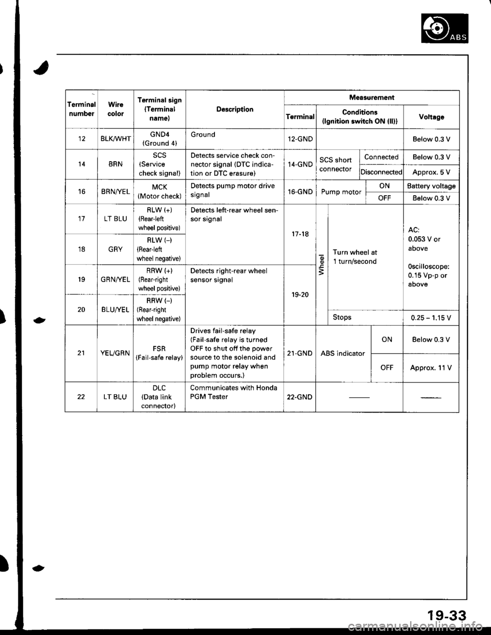
Terminal
numbel
Wire
color
Terminalsign
lTerminal
name,
Description
Measurement
T€rminalConditions(lgnition switch ON {ll}}Vohage
BLKMHTGND4(Ground 4)
G round12-GNDBelow 0.3 V
14BRN(Service
check signal)
Detects service check con-
nector signal (DTC indica-
tion or DTC erasure)
I4-GNDSCS short
connector
ConnectedBelow 0.3 V
DisconnectedApprox. 5 V
16BRNfYELMCK(Motor check)
Detects pump motor drive
srg nal16-GNDPump motorONBattery voltage
OFFBelow 0.3 V
17LT BLU
RLW (+)
{Rear-left
wheel positive)
Detects left-rear wheel sen-
sor signal
17-18
q,
3
Turn wheel at
l turn/second
AC:
0.053 V or
above
oscilloscope:
0.15 Vp-p or
aoove
18GRY
RLW (_)
(Rear-left
wheel negative)
19GRNIVEL
RRW (+)
(Rearright
wheel positive)
Detects right-rear wheel
sensor srgnal
19-20
20BLU//EL
RRW (-)
(Rear-right
wheel negative)Stops0.25 - 1.15 V
21YEUGRNFSR
{Fail-safe relay)
Drives failsafe relay
(Fail-safe relay is turned
OFF to shut off the power
source to the solenoid and
pump motor relay when
problem occurs.)
21-GNDABS indicator
ONBelow 0.3 V
OFFApprox. 11V
LT BLU
DLC(Data link
connectorl
Communicates with Honda
PGM Tester22-GND
19-33
Page 789 of 1681
I
\
I
Diagnostic Trouble Code (DTC)
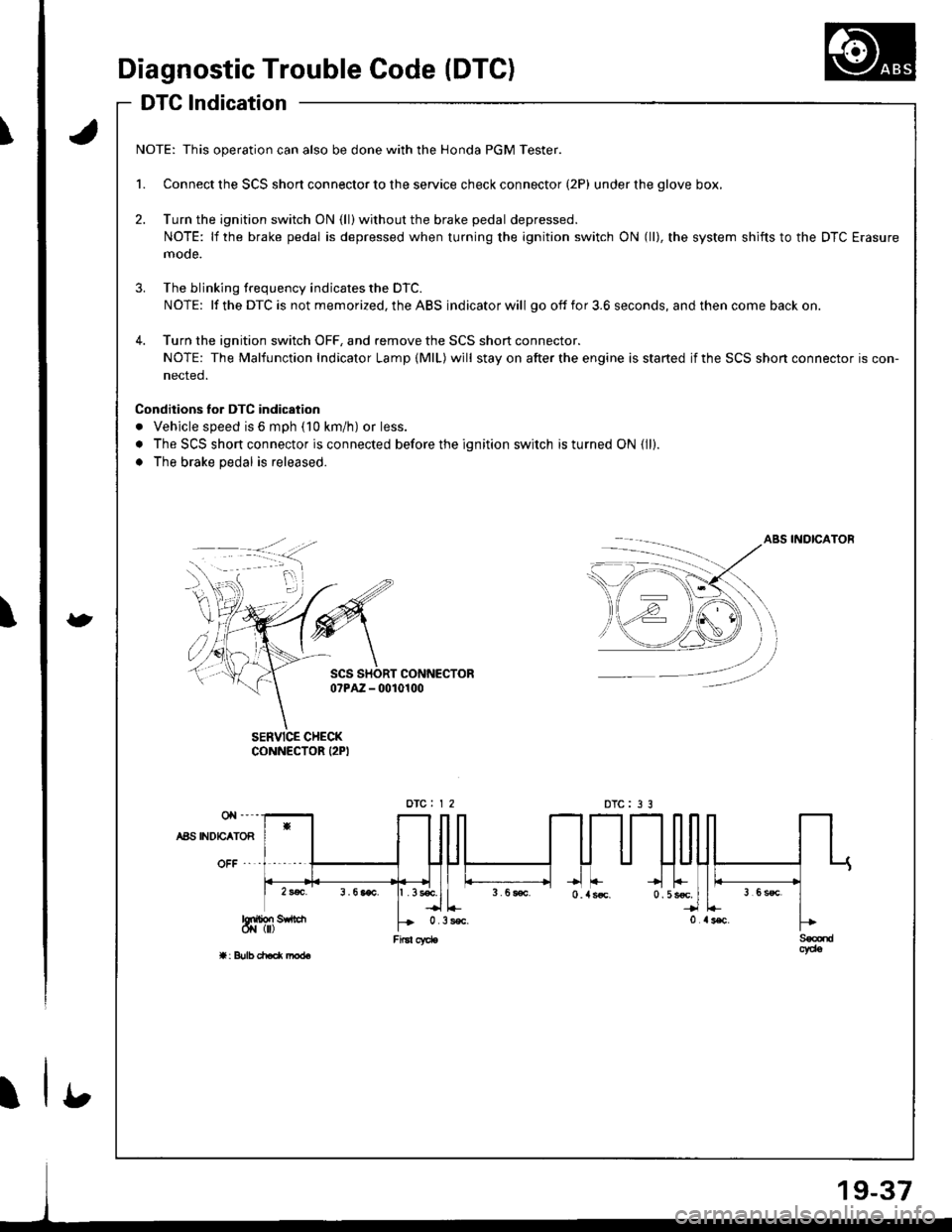
DTG lndication
a
t
NOTE: This operation can also be done with the Honda PGM Tester.
1. Connect the SCS short connector to the service check connector (2P) under the glove box,
2. Turn the ignition switch ON (ll) without the brake pedal depressed.
NOTE: lf the brake pedal is depressed when turning the ignition switch ON (ll), the system shifts to the DTC Erasure
mode.
3. The blinking frequency indicates the DTC.
NOTE: lf the DTC is not memorized, the ABS indicator will go off fo r 3.6 seconds, and then come back on.
4. Turn the ignition switch OFF, and remove the SCS short connector.
NOTE: The Malfunction Indicator Lamp (MlL) will stay on after the engine is started if the SCS shon connector is con-
nected.
Conditions lor DTC indication
. Vehicle speed is 6 mph (10 km/h) or less.
. The SCS short connector is connected before the ignition switch is turned ON {ll).
. The brake pedal is released.
ABS INOICATOB
SCS SHORT CONNECTORo?PAZ - 0010100
SERVICE CHECKCONNECTOR I2PI
DTC : 3 3
b
Page 790 of 1681
Diagnostic Trouble Code (DTC)
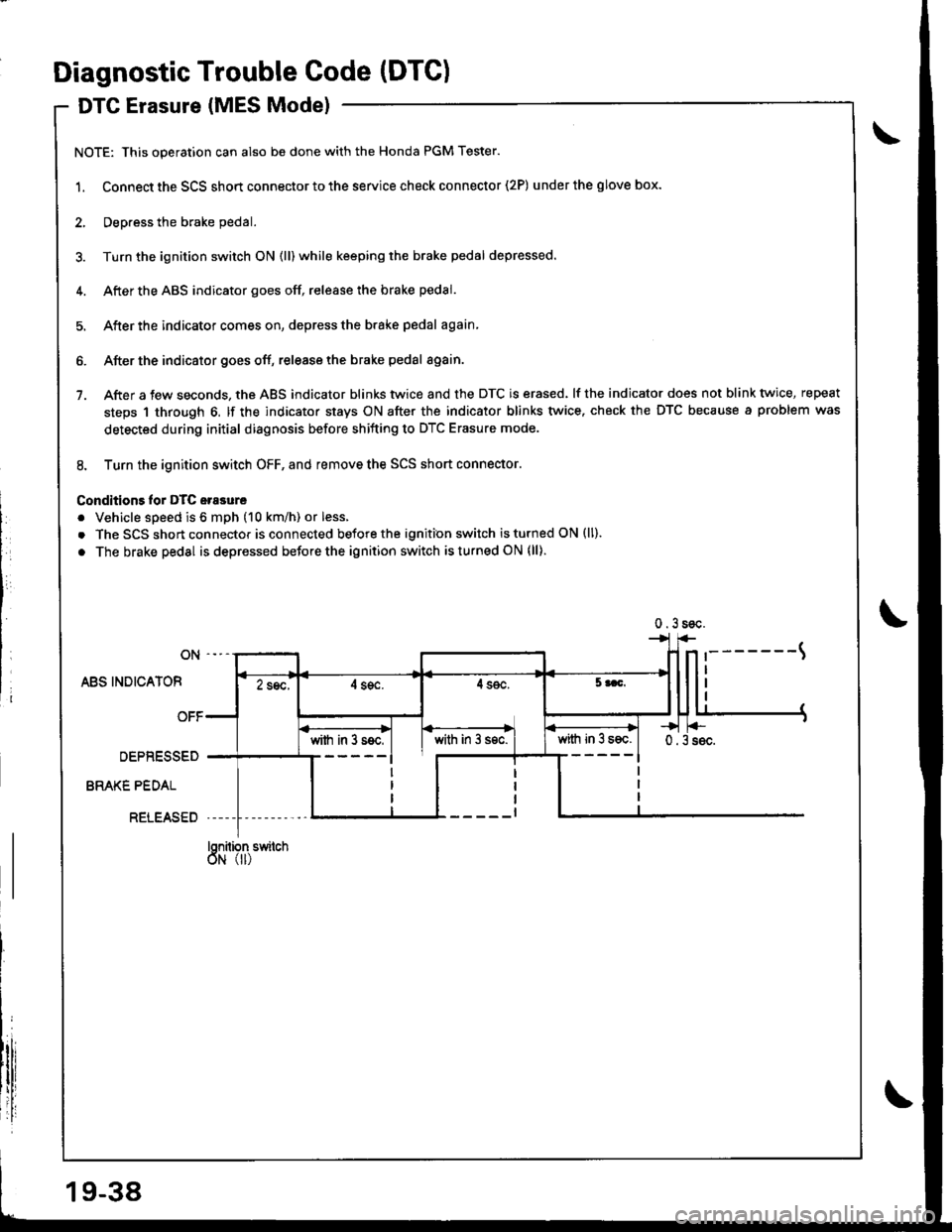
DTG Erasure (MES Mode)
NOTE: This operation can also be done with the Honda PGM Tester.
1. Connect the SCS short connector to the service check connector (2P) underthe glove box.
2, Deoress the brake pedal.
3. Turn the ignition switch ON (ll) while keeping the brake pedal depressed.
4. Afterthe ABS indicator goes off, release the brake pedal.
5. After the indicator comes on, depress the brake pedal again
6. After the indicator goes off, release the brake pedal again.
7. After a few seconds, the ABS indicator blinks twice and the DTC is erased. lf the indicator does not blink twice, repeat
steps 1 through 6. lf the indicator stays ON after the indicator blinks twice. check the DTC because a problem was
detected during initial diagnosis before shifting to DTC Erasure mode.
8. Turn the ignition switch OFF, and remove the SCS short connector.
Conditions lor DTC erasure
. Vehicle speed is 6 mph (10 km/h) or less.
. The SCS short connector is connected before the ignition switch is turned ON (ll).
. The brake pedal is depressed before the ignition switch isturned ON (ll)
ON
ABS INDICATOF
OFF
DEPRESSED
BRAKE PEDAL
RELEASED
Snilion switch
illr'I'
0.3soc.
'-------t
II2 sec,4 sgc.4 sec.5 aac.
0.3s6c.with in 3 s6c.with in 3 ssc.with in 3 s€c.
T
19-38
Page 797 of 1681
l
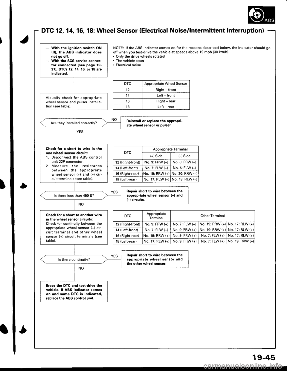
DTC121416, 18: Wheel Sensor {Electrical Noise/lntermittent lnterruptionl
- Wilh the ignition switch ONlll), the ABS indicator doesnot go off.- With the SCS service connec-tor connectcd (3e6 page 19-37), DTCa 12, 14, 16, or 18.reindicated.
Visually check for appropriatewheel sensor and pulser installation (see table).
Reinstall or replace th6 eppropri-ats wh6el sensor or puber.
Ch€ck lor a short to wire in thoone wheel s6nsor circuit:1. Disconnect the ABS controlunit 22P connector.2. Measu re the resistancebetween the appropriatewheel sensor (+) and (-) circuit terminals (see table).
Repair short to wire between theappropriate wheel sensor {+) and{-l circuits.ls there less than 450 0?
Check lor a short to .nother wirein lhe wheel sensor circuits:Check for continuity between theappropriate wheel sensor (+) circuit terminal and other wheelsensor (+i circuit terminals (see
table)-
R€psir short to wire between theappropriale wheol sensor andthe other wheel sensor.ls there continuity?
Eraso the DTC and test-drive thevehicle. lf ABS indicator comeson and same OTC is indiceted,reDlace the ABS control unil.
NOTE: ll the ABS indicator comes on for the reasons described below, the indicator should go
off when you test'drive the vehicle at speeds above 19 mph 130 km/h).. Only the drive wheels rotated. The vehicle spun. Electrical noise
DTCAppropriate Wheel Sensor
12Right - front
14Left front
Right - rear
18Left rear
DTCAppropriate Terminal
{+}Side(-)Side
12 (Right-front)No. 9: FRW (+)No.8: FRW (-)
'14 {Left-front)No. 7: FLW {+)No.6: FLW (-)'16 {Right-rear)No. 19: RRW 1+)No.20: RRW ( )
18 (Left-rear)No. 17: RLW (+)No. 18: RLW ( )
DTCAppropriateTerminalOther Terminal
12 (Right-tront)No.9: FBW (+)No. 7: FLW 1+)No. 19: RRW (+)No. 17: RLW (+)
14 (Left-front)No.7: FLW (+)No.9i FRW (+)No. 19: RRW (+)No. 17: RLW (+)
16 (Right-rear)No. 19r RRW {+)No.9: FRW (+)No. 7: FLW 1+)No.17: RLW (+)'18 (Left-rear)No. 17: RLW (+)No.9: FRW (+)No.7; FLW (+iNo. 19: RRW (+i
'
L
19-45
Page 802 of 1681
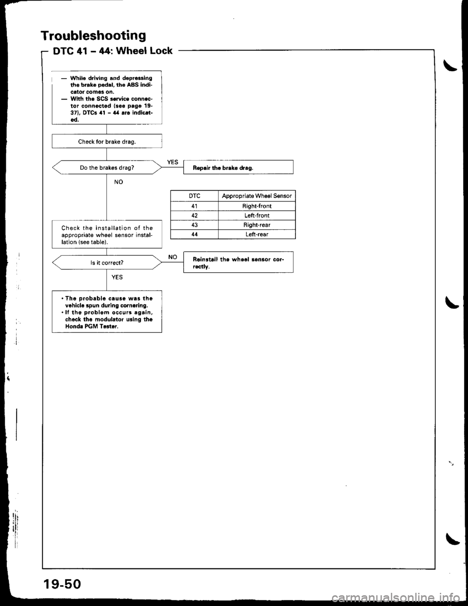
- while driving and dcprc$ingtho brakc oodrl, the ABS indi-catot com63 0n.- With the SCS service connac-tor connoctod lsoa page 19-371, DTCa 41 - a4 ar6 indicri-oo,
Do the brakos drag?
Check the installation of theappropriate wheel sensor instal-lation (see table).
. Th6 orobablo cau3o was thevehicle spun during cornaring..lf the problem occurs agcin,chock th6 modulator u.ing thoHonda PGM Tertar.
DTCAppropriate Wheel Sensor
41Right-front
42Left-front
4:]Right-rear
44Leii-rear
Troubleshooting
DTC 41 - 44: WheelLock
19-50
Page 804 of 1681
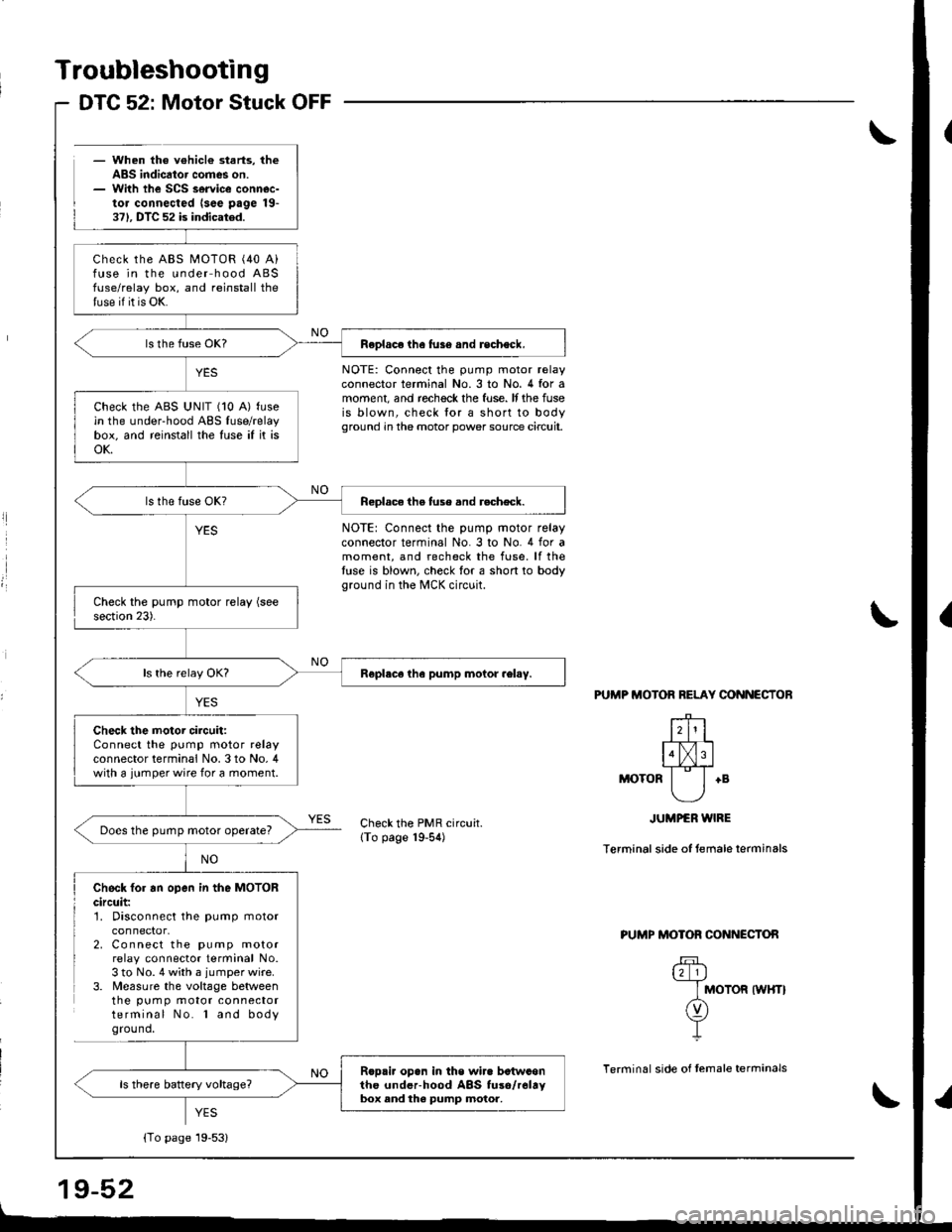
Troubleshooting
- When the v€hicl€ starts, theABS indicator comes on.- With the SCS service connec-tor connected lsee page 19-371. DTC 52 is indicated.
DTC 52: Motor Stuck OFF
l
l
NOTE: Connect the pump motor relayconnector terminal No.3 to No. 4 for amoment, and rechock the fuse. It the fuseis blown, check lor a short to bodyground in the motor power source circuit.
NOTE: Connect the pump motor relayconnector terminal No. 3 to No. 4 for amoment, and recheck the fuse. lf thetuse is blown, check for a short to bodyground in the MCK circuit.
PUTIIP MOTOR RELAY CONNECTOB
+B
Check the PMR circuit.lTo page 19-54)
JUMPER WIRE
Terminal side of temale terminals
Check fo. an open in the MOTORcircuit:1. Disconnect the pump motor
2. Connect the pump motorrelay connector terminal No.3 to No. 4 with a jumper wire.3. Measure the voltage betweenthe pum p motor connectorterminal No. l and bodyground,
PUMP MOTOR CONNECTON
u_l_lj
I MOTOR tWHTt
n)Y-L
Terminal side of temale terrninals
YES
Check the ABS MOTOR (40 A)fuse in the under hood ABSfuse/relay box, and reinstall thetuse if it is OK.
Feplace the fus6 and recheck.
check the ABS uNlT (10 A) fusein the under-hood ABS fuse/relaybox, and reinstall the fuse if it isoK.
Reolace the tuse and r.check.
Roplece tha pump motor .el.y.
Check the motor circuit:Connect the pump motor relayconnector terminal No. 3 to No, 4with a jumper wire for a moment.
Does the pump motor operate?
Rop.i. opan in the wir. betwconthc underhood ABS fuso/r6ltybox and the pump motor,
{To page 19-53}
Page 812 of 1681
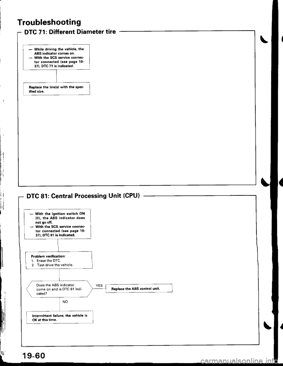
DTC 71: Different Diameter tire
- While driving the vehicl€. theABS indicator comes on.- With the SCS sorvico connec-tor connocted (see page 19-371. DTC 71 is indicated.
Troubleshooting
Central Processing Unit (CPU)
- With the ignition switch ON(lll, tho ABS indicator does
not go off.- With the SCS service connec-lor connectgd (sss page 19-
3?), DTC 81 is indic€ted.
Problem ve.ification:1. Erase the DTC.2. Test-drive the vehicle.
Does the ABS indicatorcome on and is DTC 81 indicated?
R€place th6 ABS control unit.
lntermittent failure; the vehicle is
OK rt this time.
19-60
Page 949 of 1681
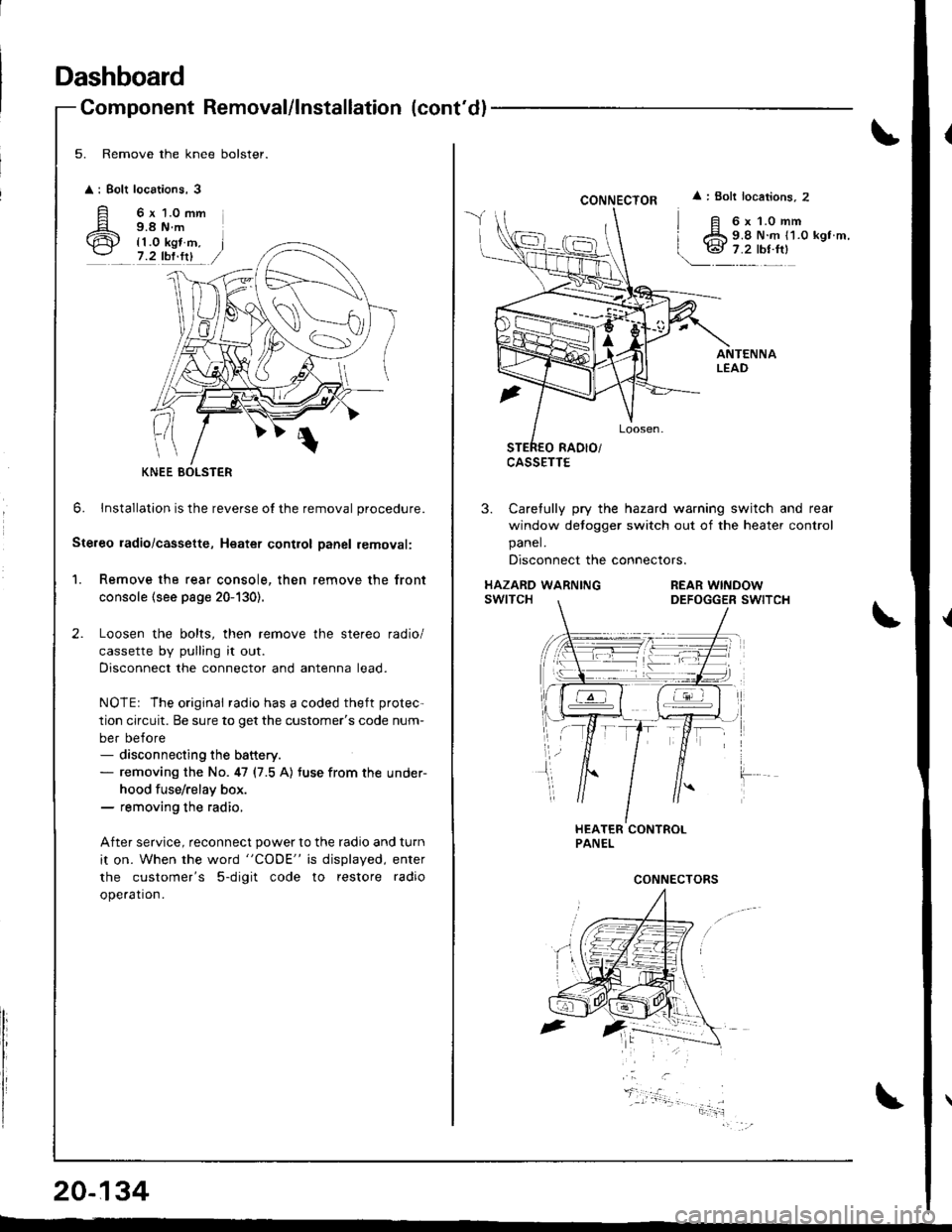
Dashboard
Component Removal/lnstallation (cont'dl
5. Remove the knee bolster.
: Bolt
A'ir
locations,3
6 x 1.0 mm9.8 N.m
{1.0 kgt m,7.2 tbf.fit
0
6. lnstallation is the reverse o{ the removal procedure.
Ste.eo ladio/cassette, Heatet contlol Danel removal:
1. Remove the rear console, then remove the front
console (see page 20-130).
Loosen the bolts, then remove the stereo radio/
cassette by pulling it out.
Disconnect the connector and antenna lead.
NOTEr The original radio has a coded theft protec-
tion circuit. Be sure to get the customer's code num-
ber before- disconnecting the battery.- removing the No. 47 (7.5 A) tuse from the under-
hood fuse/relay box.- removing the radio,
After service, reconnect power to the radio and turn
it on. When the word "CODE" is displayed, enter
the customer's 5-digit code to restore radio
ope.ation.
KNEE BOLSTER
20-134
CONNECTOR
CASSETTE
: Bolt locations, 2
6x1.0mm9.8 N.m {1.0 kgt m,
3. Carefully pry the hazard warning switch and rear
window detogger switch out of the heater control
panel.
Disconnect the connectors.
HAZARD WARNINGswtTcHREAR WINDOWDEFOGGER SWITCH
CONNECTORS